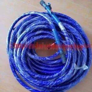
Induction Hardening Coil for Steel Surface Hardening
Induction Hardening Coil for Steel Surface Hardening | Engineering Selection Guide
Table of Contents
- Quick Answer
- What Is This Product?
- Key Applications
- Suitable Materials
- Working Principle
- Technical Specifications
- Recommended Model Selection
- Process Workflow
- Coil and Fixture Design
- Control System and Automation
- Common Problems and Solutions
- Engineering Selection Guide
- Advantages
- Limitations
- Why Choose HLQ Induction Equipment?
- FAQ
An induction hardening coil is the water-cooled copper inductor used in an induction hardening machine to heat a selected surface area of steel or cast-iron parts before quenching. It is used for shafts, gears, pins, rollers, bearing races, sprockets, splines, crankshafts, camshafts and guideways. The coil controls heating pattern, case depth, temperature uniformity and production repeatability. For buyers, a correctly designed hardening coil solves problems such as soft spots, uneven case depth, overheating at edges, excessive distortion, low efficiency, coil burnout and unstable hardening quality.
Quick Answer
An induction hardening coil is a specially designed copper heating inductor that converts electrical energy from an induction power supply into a concentrated electromagnetic field around the workpiece surface. Its best-fit application is localized surface hardening of medium-carbon steel, alloy steel, bearing steel and selected cast-iron parts where high surface hardness, controlled case depth and a tough core are required. In an induction hardening system, the coil is not a simple accessory; it is the key process tool that determines heating accuracy, hardened pattern, energy efficiency and final metallurgical quality.
What Is This Product?
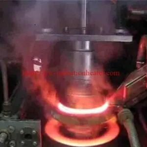
An induction hardening coil, also called a hardening inductor or induction quenching coil, is a precision-engineered copper coil used to heat a metal part by electromagnetic induction. During operation, alternating current passes through the coil and generates an alternating magnetic field. This magnetic field induces eddy currents in the surface of the workpiece, causing rapid localized heating. When the surface reaches the austenitizing temperature, a quenching medium is applied to produce a hardened martensitic layer.
In practical engineering, the coil is one of the most important components of the entire hardening process. The induction power supply provides energy, but the coil decides where the energy goes. A good coil directs heat to the required surface, avoids unnecessary heating, maintains consistent coupling distance, allows stable quenching and produces repeatable hardening results. A poor coil can cause overheating, underheating, cracking, irregular hardness, unstable case depth, short coil life and high scrap rate.
Induction hardening coils are usually fabricated from oxygen-free copper tube or copper profile. The copper conductor is water-cooled because the coil carries high current and operates close to a hot workpiece. The coil may be round, square, oval, rectangular, U-shaped, hairpin-shaped, internal, external, split, single-turn, multi-turn, scanning type, single-shot type or profile-matched according to the workpiece geometry. For complex hardening patterns, magnetic flux concentrators may be attached to control the magnetic field and improve heating efficiency.
According to technical references on induction coil design, important design factors include workpiece shape, required hardness pattern, coupling efficiency, frequency, number and spacing of turns, and use of flux intensifiers. These factors directly affect the distribution of eddy currents and heat in the component.
Key Applications
Induction hardening coils are used in many industries where metal parts require improved surface hardness and wear resistance. The coil must be designed according to the part, not only according to the power supply. Different applications require different coil shapes, coupling distances, quench arrangements and magnetic field control methods.
1. Shaft Hardening Coils
Shaft hardening coils are used for motor shafts, transmission shafts, spline shafts, pump shafts, axle shafts, hydraulic rods and rotor shafts. For long cylindrical parts, scanning hardening coils are common. The shaft rotates while the coil moves along the hardening zone. A quench ring is usually placed just below or behind the coil to cool the heated surface immediately.
2. Gear Hardening Coils
Gear hardening requires precise control of tooth flank, tooth root and transition zone. Depending on gear size and hardness pattern, the coil may be designed for spin hardening, tooth-by-tooth hardening, gap-by-gap hardening or dual-frequency hardening. Gear hardening coils often require magnetic flux concentrators to direct heat into the tooth profile and reduce overheating at tooth tips.
3. Bearing Race Hardening Coils
Bearing races and rings require uniform hardness and controlled case depth on the raceway. Circular coils, split coils, internal coils and scanning coils are used depending on whether the inner raceway, outer raceway or end face needs hardening. For large slewing rings, the coil may scan around the circumference while the ring rotates.
4. Pin and Bushing Hardening Coils
Pins, bushings, sleeves and track pins are usually hardened on the outer diameter, inner diameter or both. External circular coils are used for outside surfaces, while internal inductors are used for bore hardening. These parts are common in excavators, loaders, agricultural machinery and mining equipment.
5. Crankshaft and Camshaft Hardening Coils
Crankshafts and camshafts require profile-specific coils because the heating zones are not simple cylinders. The coil must follow journals, fillets or cam lobes accurately. Incorrect coil shape can cause soft fillets, overheated edges or excessive distortion.
6. Guideway and Rail Hardening Coils
Machine tool guideways, linear rails and sliding surfaces are hardened with special profile coils. The challenge is to maintain straightness, uniform case depth and consistent surface hardness over a long length. The coil may be mounted on a horizontal scanner with controlled movement and integrated spray quenching.
7. Roller, Wheel and Ring Hardening Coils
Rollers, crane wheels, support wheels, conveyor rollers and large rings need high wear resistance on rolling-contact surfaces. The coil design must compensate for edge effects, changing section thickness and quench uniformity.
Suitable Materials
An induction hardening coil can heat most conductive metals, but induction hardening is metallurgically suitable mainly for steels and cast irons that can form martensite after rapid cooling. The material must have adequate carbon content and hardenability.
| Material Type | Typical Grades | Suitability | Engineering Notes |
|---|---|---|---|
| Medium-carbon steel | 45 steel, C45, 1045, S45C | Excellent | Common for shafts, pins, sprockets and rollers. Good response to direct induction hardening. |
| Alloy structural steel | 40Cr, 42CrMo, 4140, 4340, SCM440 | Excellent | Suitable for deeper case depth, heavy-duty parts and high fatigue requirements. |
| Bearing steel | GCr15, 52100 | Excellent | Used for bearing races, rolling surfaces and precision wear parts. |
| Spring steel | 65Mn, 60Si2Mn | Good | Requires controlled quenching and tempering to avoid cracking. |
| Ductile cast iron | QT500, QT600, QT700 | Good | Used for gears, cams, guideways and wear surfaces; matrix structure affects hardening response. |
| Gray cast iron | HT250, HT300 | Conditional | Can be surface hardened for guideways and sliding surfaces, but process control is critical. |
| Low-carbon steel | Q235, A3, 1018 | Poor for direct hardening | Usually requires carburizing, carbonitriding or alternative surface treatment before hardening. |
| Martensitic stainless steel | 420, 440C | Conditional | Can be hardened with careful temperature control and suitable quenching practice. |
| Austenitic stainless steel | 304, 316 | Not suitable for conventional hardening | Can be induction heated, but does not obtain conventional martensitic hardening like carbon steel. |
Working Principle
The working principle of an induction hardening coil is based on electromagnetic induction and the skin effect. When alternating current flows through the copper coil, it creates an alternating magnetic field. When a conductive workpiece is placed inside or near this magnetic field, eddy currents are generated in the workpiece surface. These eddy currents produce heat because of electrical resistance. In ferromagnetic steels, magnetic hysteresis also contributes to heating below the Curie temperature.
The heating depth depends strongly on power density, frequency, heating time, workpiece material and coil geometry. Higher frequency usually produces shallower heating, while lower frequency allows deeper heat penetration. For induction hardening, power and frequency are two major factors affecting case depth, and different power-frequency combinations may achieve similar results if properly engineered. 
The coil does not touch the workpiece. Heating occurs through the electromagnetic field. This non-contact heating method allows rapid, localized and repeatable surface treatment. After the surface reaches the required austenitizing temperature, quenching is applied immediately to transform the heated layer into martensite. The result is a hard surface layer with improved wear resistance and fatigue strength, while the core remains tougher and less affected.
Magnetic flux concentrators are often used in induction hardening coils. These components guide and concentrate the magnetic field, helping the coil heat the desired area more selectively. Technical sources describe magnetic flux concentrators as low-reluctance paths that focus the magnetic field around the coil and improve heating control.
In hardening drawings and inspection documents, case depth terminology should be clearly defined. ISO 15787 states that hardness depth should be indicated according to the heat treatment method, including surface-hardening hardness depth, case-hardening hardness depth or nitriding hardness depth. This is important because coil design must match the specified hardened depth and pattern.
Technical Specifications
| Parameter | Specification | Notes |
|---|---|---|
| Product Name | Induction Hardening Coil / Hardening Inductor | Customized according to workpiece geometry and hardening pattern. |
| Coil Material | Oxygen-free copper tube, copper profile or copper plate | High conductivity copper improves efficiency and reduces heating loss. |
| Cooling Method | Internal water cooling | Required because the coil carries high current and operates near hot parts. |
| Coil Type | Single-turn, multi-turn, scanning, single-shot, split, internal, external, profile coil | Selected according to part shape and hardening requirement. |
| Power Range | 10–1000 kW system compatible | Actual rating depends on power supply, workpiece size and production takt time. |
| Frequency Range | 1–500 kHz typical | Low frequency for deeper case; high frequency for shallow case and small parts. |
| Applicable Case Depth | Approx. 0.5–10 mm | Depends on material, frequency, power density and heating time. |
| Workpiece Diameter | Customized from small pins to large rings | Coil opening and coupling gap are designed according to part size. |
| Quench Integration | Separate quench ring, integrated spray holes or combined heat-quench inductor | Quench position and delay are critical for hardness quality. |
| Magnetic Flux Concentrator | Optional soft magnetic composite, laminated steel or ferrite-type materials | Used to focus heat, improve efficiency and reduce unwanted heating. |
| Insulation | High-temperature electrical insulation, ceramic, epoxy, fiberglass or protective coating | Prevents arcing, short circuit and accidental contact. |
| Mounting Interface | Custom copper busbar, quick-change connector or transformer output adapter | Must match induction transformer and machine structure. |
| Expected Coil Life | Application dependent | Influenced by cooling water quality, alignment, quench corrosion, overheating and operator handling. |
| Inspection Before Delivery | Water pressure test, flow test, dimensional check, electrical insulation check | Recommended before production use. |
Recommended Model Selection
| Application | Material | Recommended Power | Frequency |
|---|---|---|---|
| Small pin and small shaft hardening coil | 45 steel, 1045, 40Cr | 20–60 kW | 30–150 kHz |
| Medium shaft scanning hardening coil | 45 steel, 40Cr, 4140 | 60–160 kW | 8–50 kHz |
| Heavy shaft and excavator pin hardening coil | 42CrMo, 4140, 4340 | 160–400 kW | 1–20 kHz |
| Small gear spin hardening coil | 40Cr, 42CrMo, 1045 | 50–150 kW | 20–100 kHz |
| Large gear tooth-by-tooth hardening coil | 42CrMo, 50Mn, alloy steel | 100–500 kW | 3–30 kHz |
| Bearing race hardening coil | GCr15, 52100 | 80–300 kW | 5–50 kHz |
| Internal bore hardening coil | Alloy steel, bearing steel | 30–200 kW | 10–100 kHz |
| Guideway and rail hardening coil | Cast iron, alloy steel | 80–300 kW | 5–50 kHz |
| Camshaft and crankshaft profile hardening coil | Alloy steel, ductile iron | 100–350 kW | 3–30 kHz |
| Large roller and wheel hardening coil | 4140, 42CrMo, cast steel | 200–800 kW | 1–15 kHz |
Process Workflow
The design and use of an induction hardening coil should follow a controlled engineering workflow. The objective is not only to make a copper coil that fits the part, but to produce the required hardened layer repeatedly in real production.
- Collect workpiece data: Confirm drawing, material grade, hardness requirement, effective case depth, hardened area, tolerance and production rate.
- Analyze hardening pattern: Identify the exact surface to be hardened and areas where heating must be avoided.
- Select process method: Choose scanning hardening, single-shot hardening, spin hardening, tooth-by-tooth hardening or internal hardening.
- Choose frequency and power: Match frequency to case depth and power to heating speed and production takt time.
- Design coil geometry: Determine coil shape, turn number, copper tube size, coupling distance and lead arrangement.
- Design quench arrangement: Select integrated spray, separate quench ring or delayed quench system.
- Add flux concentrators if needed: Use magnetic field control for shoulders, gear teeth, edges, fillets and localized zones.
- Build coil and fixture: Fabricate copper coil, insulation, water circuit, mounting base and positioning fixture.
- Test water cooling: Verify water flow, pressure, leakage, blockage and cooling stability.
- Run trial hardening: Test parts and measure surface hardness, case depth, hardened pattern, cracks and distortion.
- Adjust parameters: Correct power, time, scan speed, coil gap, quench flow and quench delay.
- Release for production: Save process recipe and define inspection frequency.
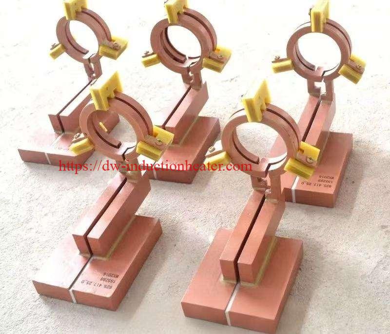
Coil and Fixture Design
Coil and fixture design must be considered together. A precise coil cannot produce stable results if the fixture cannot hold the workpiece accurately. Likewise, a rigid fixture cannot compensate for poor magnetic field distribution. The best induction hardening results come from the combined design of coil, fixture, quenching and motion control.
1. Coil Shape
The coil shape should follow the surface to be hardened. A round shaft normally uses a circular coil. A flat guideway may use a rectangular or profile coil. A gear may use a circular spin coil or tooth-profile inductor. A crankshaft journal may require a special inductor with shaped copper and magnetic concentrators.
2. Coupling Distance
Coupling distance is the gap between the coil and the workpiece. A smaller gap improves heating efficiency but increases the risk of collision, arcing and overheating. A larger gap is safer but reduces efficiency and may require more power. In production, the gap must remain consistent around the part and along the scan path.
3. Number of Turns
Single-turn coils are common for high-power, localized heating. Multi-turn coils provide longer heating zones and may improve uniformity for some parts. However, excessive turns may increase voltage, reduce control of the heating zone or create unwanted end effects.
4. Copper Tube Size
The copper tube must be large enough to carry current and cooling water. Small tubes are easier to bend but may overheat or restrict water flow. Large tubes improve cooling and current capacity but may be difficult to shape for small or complex parts.
5. Coil Leads
Coil leads should be short, rigid and properly cooled. Poor lead design wastes power, increases heating of the lead section and may disturb the magnetic field. Lead-to-lead spacing and proximity to metallic structures should be considered because unnecessary heating loss can reduce power available to the workpiece.
6. Magnetic Flux Concentrators
Flux concentrators are used to focus the magnetic field, improve coil efficiency and reduce unwanted heating. They are especially useful for gear tooth hardening, shoulder hardening, fillet hardening, internal bore hardening and local surface hardening. Technical literature identifies selective heating, efficiency improvement and field control as traditional functions of flux concentrators in induction hardening. 
7. Integrated Quenching
For induction hardening, heating and quenching must be coordinated. Some coils include integrated quench holes or a quench jacket. Others use a separate quench ring mounted close to the coil. The quench position, spray angle, flow rate and delay time directly affect hardness, case depth and cracking risk.
8. Fixture Accuracy
The fixture must keep the part centered and stable. For round parts, runout must be controlled. For long shafts, supports may be needed to reduce vibration. For gears and rings, the fixture must locate the workpiece concentrically. For scanning hardening, the axis of movement must be parallel to the workpiece surface.
Control System and Automation
Although the coil is a mechanical-electrical tool, its performance depends heavily on machine control. The induction hardening machine must control power output, frequency matching, heating time, scan speed, rotation speed, quench delay and cooling water status. In automated systems, each part number should have a stored recipe linked to the correct coil and fixture.
Important Control Parameters
- Power output: Controls heating rate and surface temperature.
- Frequency: Affects current penetration and case-depth tendency.
- Heating time: Determines total energy input during single-shot hardening.
- Scanning speed: Controls heat input per unit length during scanning hardening.
- Rotation speed: Improves circumferential uniformity on shafts, gears and rings.
- Quench delay: Controls the time between heating and cooling.
- Quench flow: Affects cooling rate and martensite formation.
- Coil position: Maintains consistent coupling and hardening pattern.
For high-value parts, sensors may be added to monitor water flow, water temperature, coil position, transformer temperature, power output, current, voltage and quench pressure. Pyrometers or thermal imaging can be used for process development or closed-loop control, although surface emissivity and quench spray interference must be considered.
Automation can include automatic coil change, servo gap control, robotic loading, QR code part recognition, automatic recipe selection and data logging. These functions are especially useful for automotive, bearing, construction machinery and high-volume shaft production.
Common Problems and Solutions
| Problem | Possible Cause | Engineering Solution |
|---|---|---|
| Uneven hardness around circumference | Workpiece runout, uneven coil gap, unstable rotation or incorrect coil alignment | Improve fixture concentricity, adjust coil position, check chuck accuracy and stabilize rotation speed. |
| Case depth too shallow | Frequency too high, power too low, heating time too short or scan speed too fast | Use lower frequency, increase power, reduce scan speed or increase heating time. |
| Case depth too deep | Frequency too low, heating time too long or excessive power density | Increase frequency, reduce power, shorten heating time or modify coil coupling. |
| Soft spots after hardening | Poor coil coverage, wrong quench timing, uneven quench spray or dirty workpiece surface | Redesign coil pattern, adjust quench delay, clean spray holes and prepare the surface properly. |
| Overheating at edges or shoulders | Magnetic field concentration at sharp geometry | Modify coil shape, increase local gap, add flux concentrator or reduce local power density. |
| Cracking after quenching | Excessive surface temperature, aggressive quenching, high carbon content or sharp corner stress | Reduce temperature, adjust quench medium, add tempering, improve part radius and optimize spray pattern. |
| Coil overheating | Insufficient cooling water, blocked copper tube, wrong copper size or excessive current | Increase water flow, clean coil channels, enlarge copper tube and verify transformer matching. |
| Coil arcing or short circuit | Insufficient insulation, too small gap, metal chips, water leakage or poor maintenance | Improve insulation, clean work area, repair leaks and increase safe clearance. |
| Low heating efficiency | Large coil gap, poor coil shape, wrong frequency or magnetic field leakage | Optimize coupling, redesign coil, add flux concentrator and verify power-frequency matching. |
| Short coil life | Thermal fatigue, corrosion, vibration, poor cooling water quality or operator collision | Improve cooling, use proper water treatment, strengthen coil support and add collision protection. |
Engineering Selection Guide
Selecting or designing an induction hardening coil requires a systematic engineering review. The following points should be confirmed before manufacturing the coil.
1. Define the Hardened Area Clearly
The hardened area should be marked on the part drawing. The drawing should identify where hardening is required and where hardening is not allowed. Without this information, the coil designer may produce a heating pattern that does not match the functional surface.
2. Confirm Required Hardness and Case Depth
Surface hardness and effective case depth must be specified. A common mistake is to specify only surface hardness. However, surface hardness alone does not guarantee sufficient load-bearing capacity. Case depth must be inspected according to the customer’s standard or applicable heat-treatment specification.
3. Match Frequency to Case Depth
A shallow case usually requires higher frequency, while a deeper case requires lower frequency. For example, small pins and shallow gear tooth hardening may use high frequency, while large shafts and heavy-duty pins may require medium frequency or lower frequency.
4. Match Power to Production Rate
A coil may heat correctly in a laboratory test but fail in production if power is too low for the required cycle time. Production takt time, part mass and heated area must be considered.
5. Evaluate Workpiece Geometry
Corners, keyways, oil holes, shoulders, grooves, thin sections and wall thickness changes can all affect heat distribution. These features should be reviewed before coil design. Magnetic concentrators or local coil gap adjustments may be required.
6. Design Quenching Together with the Coil
The quench system should not be added after coil design as an afterthought. Spray direction, spray pressure, flow rate and delay time must match the coil and the part. Poor quenching can ruin an otherwise good heating pattern.
7. Consider Maintenance and Coil Change
Production coils should be easy to install, align, inspect and replace. Quick-change connectors, positioning pins and clear water connections reduce downtime and operator error.
8. Validate with Sample Testing
The final coil should be validated by hardening sample parts, cutting sections and measuring hardness profile. Only after test results match the requirement should the coil be released for production.
Advantages
- Precise localized heating: The coil heats only the required area, reducing unnecessary thermal impact.
- Fast production cycle: Induction coils can heat surfaces within seconds for many applications.
- Controlled hardening pattern: Coil shape and flux control allow customized hardened zones.
- Energy efficiency: Proper coil coupling improves power transfer to the workpiece.
- Reduced distortion: Local heating reduces total heat input compared with furnace hardening.
- Good automation compatibility: Coils can be integrated with CNC scanners, robots and production lines.
- Repeatable quality: A stable coil and fixture produce consistent heating patterns.
- Flexible design: Coils can be customized for shafts, gears, rings, pins, rails and complex parts.
- Cleaner working environment: No flame is required, and heating is electrically controlled.
- Lower post-processing cost: Better hardening control can reduce grinding allowance and scrap rate.
Limitations
- Custom design required: Most hardening coils are workpiece-specific and cannot be used universally.
- Geometry sensitivity: Complex shapes can create local overheating or soft areas.
- Cooling requirement: The coil must have stable water cooling to avoid burnout.
- Maintenance requirement: Coils can be damaged by collision, corrosion, blockage or arcing.
- Material limitation: The coil can heat many metals, but hardening depends on material hardenability.
- Testing required: Final coil performance must be validated by hardness and case-depth inspection.
- Process dependency: Coil performance depends on correct power, frequency, fixture, quench and control settings.
Why Choose HLQ Induction Equipment?
HLQ Induction Equipment provides customized induction hardening coils and complete induction hardening systems for manufacturers that need stable surface hardening quality. HLQ focuses not only on copper coil fabrication, but also on complete process engineering, including power supply matching, coil design, fixture design, quench integration and production commissioning.
Customized Coil Engineering
HLQ designs induction hardening coils according to workpiece drawings, material grade, case depth, hardness requirement, hardened pattern and production rate. This helps customers avoid common problems such as wrong frequency selection, poor coil coupling, edge overheating and uneven quenching.
Complete System Matching
A hardening coil must match the induction power supply, transformer, CNC scanner and quenching system. HLQ can provide complete matching solutions, reducing integration risks for the buyer.
Practical Manufacturing Experience
HLQ coil designs can be applied to shaft hardening, gear hardening, pin hardening, bearing race hardening, roller hardening, guideway hardening and other industrial applications. The design can be optimized for manual operation, semi-automatic machines or fully automated CNC hardening lines.
Support for Process Testing
For new parts, HLQ can support sample testing and parameter development. Hardness, case depth, deformation and visual quality can be reviewed to refine coil geometry and process settings before production.
Buyer-Oriented Solutions
For buyers, the main value is reliable production quality. HLQ can help select coil type, power, frequency, quench method, fixture structure and automation level according to real production needs.
FAQ
1. What is an induction hardening coil?
An induction hardening coil is a water-cooled copper inductor used to generate an alternating magnetic field around a metal workpiece. It heats the required surface area before quenching, producing a hardened surface layer.
2. Is the induction hardening coil the same as the induction power supply?
No. The power supply generates high-frequency or medium-frequency current, while the coil delivers the electromagnetic field to the workpiece. The coil is the process tool that controls where and how the part is heated.
3. What materials are induction hardening coils made from?
Most induction hardening coils are made from oxygen-free copper tube, copper bar or copper plate. Copper is used because it has high electrical conductivity and good thermal conductivity.
4. Why must the coil be water-cooled?
The coil carries high current and operates close to a hot workpiece. Internal water cooling prevents overheating, oxidation, insulation damage and coil failure.
5. How is coil shape selected?
Coil shape is selected according to workpiece geometry, hardened area, case depth, production method and quenching arrangement. Round parts often use circular coils, while gears, rails and complex profiles require customized inductors.
6. What is the correct gap between coil and workpiece?
The correct gap depends on part size, power, frequency and safety clearance. A smaller gap improves efficiency, but it must be large enough to avoid collision, arcing and dimensional variation problems.
7. What is a scanning hardening coil?
A scanning hardening coil heats a moving zone while the coil or workpiece travels along the part. It is commonly used for shafts, rods, pins, rollers and guideways.
8. What is a single-shot hardening coil?
A single-shot hardening coil heats the full required hardened area at one time. It is suitable for short zones, rings, gears, local surfaces and high-speed production when the coil can cover the target area.
9. What is an internal hardening coil?
An internal hardening coil is designed to heat the inside surface of a hole, bore or internal raceway. It is used for bushings, bearing rings, sleeves and hollow parts.
10. What are magnetic flux concentrators?
Magnetic flux concentrators are high-permeability materials added to the coil to guide and concentrate the magnetic field. They improve heating focus, efficiency and pattern control.
11. Why does a coil cause overheating at edges?
Edges and shoulders can concentrate the electromagnetic field, causing faster local heating. Coil shape, coupling distance, power profile and magnetic concentrators must be adjusted to reduce this effect.
12. How long does an induction hardening coil last?
Coil life depends on cooling water quality, current load, operator handling, quench corrosion, vibration, insulation condition and collision risk. Proper maintenance can significantly extend coil life.
13. Can one coil be used for different parts?
Sometimes, if the parts have similar size, geometry and hardening requirements. However, most precision hardening applications require a dedicated coil for each part family.
14. What information is needed to design a hardening coil?
The buyer should provide part drawings, material grade, required hardness, case depth, hardened area, production rate, available machine power, frequency range and quenching requirements.
15. Can HLQ design a customized induction hardening coil?
Yes. HLQ can design customized induction hardening coils for shafts, gears, pins, rings, rollers, guideways and special-shaped parts. The coil can be matched with HLQ induction power supplies, CNC scanners, fixtures and quenching systems.