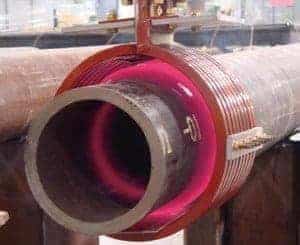
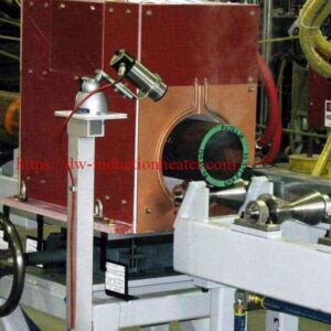
Pipe-Tube Heating Systems With Induction
Pipe and Tube Heating Systems with Induction for Production Lines
Quick Answer
Induction pipe and tube heating systems heat the pipe wall directly with an encircling or end-heating coil. The pipe either passes through the coil on a conveyor or sits with its end inside the coil.
- Range: HLQ MF-25 to MF-500 systems (25–500 kW, 0.5–30 kHz) cover pipe from Ø20 to Ø1500 mm and walls from 2 to 100 mm, up to 1250 °C.
- Uses: Quench and temper, annealing, end upsetting, bending, coating cure, stress relief and weld preheat.
- Sizing rule: Power = throughput × enthalpy ÷ efficiency. For example, 1 t/h of steel heated to 1000 °C needs about 290 kW. Choose a lower frequency for thick walls and a higher frequency for thin tubes.

What is the Pipe and Tube Heating System with Induction?
Pipe and tube induction heating is the most energy-efficient and controllable way to apply heat during the production of tubular products. Processing pipe and tube involves drilling, threading, welding and other mechanical deformation, which may require heat treatment to harden the metal or to remove residual stresses. In addition, tube and pipe ends are often heated and then upset (formed) to increase or decrease the diameter or wall thickness, so that pipes can be joined end to end.
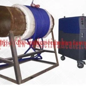
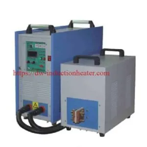
An HLQ system combines an IGBT medium-frequency power supply, a matched capacitor bank, water-cooled coils, pyrometers and a PLC with recipes. It can be built into a continuous line or used as an end-heating station. For an overview of all pipe heating uses, see induction pipe and tube heating applications.

| Heating type | How it works | Used for |
|---|---|---|
| Through (in-line) heating | The pipe moves through one or more encircling coils | Quench and temper, annealing, coating cure, billet pre-heating |
| End heating | A set length of the pipe end sits in the coil | Upsetting, swage-end stress relief, tool-joint preheat |
| Narrow-band heating | A short heated zone moves along the pipe | Hot bending |
| Zone heating | A fixed band of the pipe is heated | Weld preheat, PWHT, de-bonding |
Key Applications
HLQ induction pipe and tube heating systems are designed for a range of applications, including:
| Application | Typical temperature | Heating type |
|---|---|---|
| Heat treat quench and temper of tubing and pipe | 850–920 °C / 550–700 °C | Through heating |
| Upset processing for heat treating | 850–920 °C | End heating |
| Pre-heating for upsetting; heating rod upsetting | 1150–1250 °C | End heating |
| Swage-end stress relieving | 550–650 °C | End heating |
| Preheating tool joints | 200–400 °C | Zone heating |
| Curing and pre-heating of coatings | 180–300 °C | Through heating |
| Swivel-joint bending; pipe bending | 850–1050 °C | Narrow-band heating |
| De-bonding of rubber | 150–250 °C | Zone heating |
| Continuous coiled-tube processing | Per process | Through heating |
| Seamless mill billet pre-heaters; seamless finishing taper re-heaters | 1200–1280 °C | Through heating |
| Solution annealing; bright annealing (stainless) | 1040–1100 °C | Through heating (protective gas for bright annealing) |
| Hot reduction; hybrid gas/induction lines | 900–1250 °C | Through heating |
Application cases

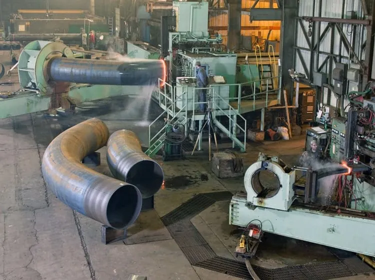
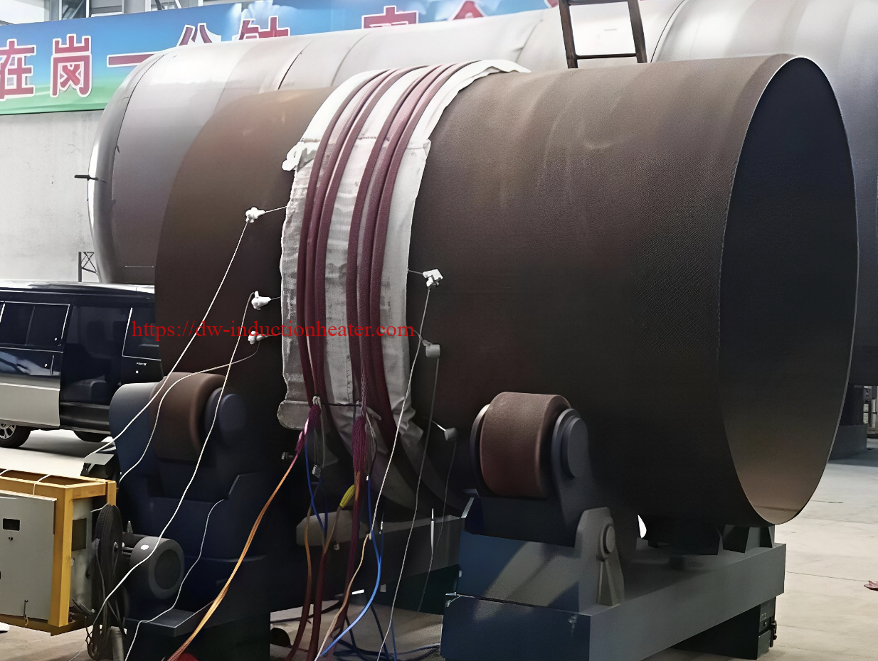
For field welding, see induction preheating before welding for pipelines and the induction post weld heat treatment machine.
Suitable Materials
| Material | Magnetic? | Typical processes | Note |
|---|---|---|---|
| Carbon and low-alloy steel pipe (API 5L, ASTM A106/A53) | Yes, below ≈ 770 °C | Q&T, normalising, bending, upsetting, coating | Very efficient to the Curie point; less efficient above it |
| OCTG casing and tubing (J55, N80, L80, P110) | Yes | Q&T, end upsetting, stress relief | Tight hardness bands, so pyrometer control is needed |
| Cr-Mo alloy pipe (P11, P22, P91) | Yes | Bending, PWHT, tempering | Respect the Ac1 limit for P91 |
| Austenitic stainless tube (304, 316) | No | Solution and bright annealing | Bright annealing needs H₂ or N₂/H₂ atmosphere |
| Duplex stainless | Partly | Solution annealing | Fast quench to avoid sigma phase |
| Copper and brass tube | No | Annealing, brazing | Low resistivity, so higher frequency is needed |
| Aluminium tube | No | Annealing, coating | Low resistivity, so higher frequency is needed |
Working Principle
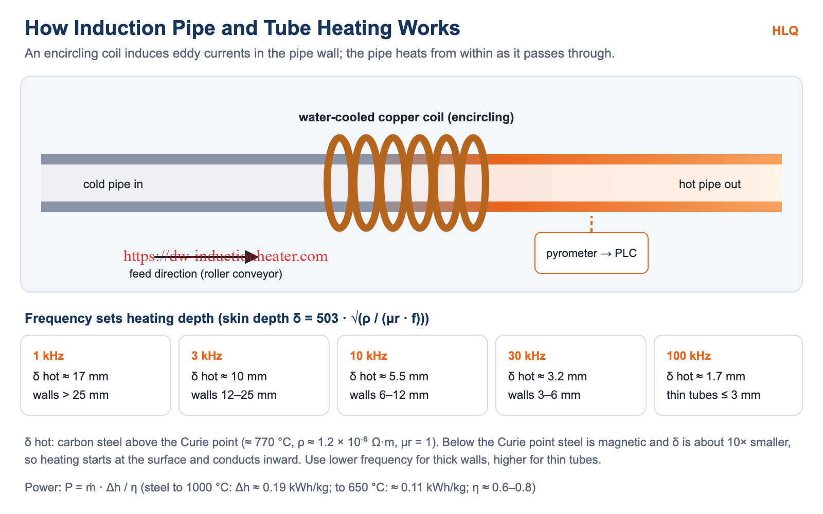
- Power conversion: An IGBT inverter converts 3-phase mains into medium-frequency current (0.5–30 kHz), tuned by a capacitor bank.
- Induction: The water-cooled copper coil creates an alternating magnetic field. Eddy currents flow in the pipe wall and heat it from within.
- Depth control: Frequency sets the current depth δ = 503 · √(ρ / (μr · f)). A lower frequency heats thicker walls through; a higher frequency suits thin tubes.
- Temperature control: Pyrometers measure the exit temperature, and the PLC trims power or line speed to stay within ±3–5 °C.
Background: how induction heating works.
Skin depth of carbon steel by frequency
| Frequency | Cold steel (μr ≈ 100) | Above Curie (μr = 1) | Suitable wall thickness |
|---|---|---|---|
| 1 kHz | 0.64 mm | 17.4 mm | > 25 mm |
| 3 kHz | 0.37 mm | 10.1 mm | 12–25 mm |
| 10 kHz | 0.20 mm | 5.5 mm | 6–12 mm |
| 30 kHz | 0.12 mm | 3.2 mm | 3–6 mm |
| 100 kHz | 0.06 mm | 1.7 mm | ≤ 3 mm |
Cold: ρ ≈ 1.6 × 10⁻⁷ Ω·m. Above the Curie point (≈ 770 °C): ρ ≈ 1.2 × 10⁻⁶ Ω·m.
Technical Specifications
| Model | Power | Frequency | Pipe Ø | Wall | Heating length | Temperature | Cooling |
|---|---|---|---|---|---|---|---|
| MF-25 | 25 kW | 10–30 kHz | 20–100 mm | 2–10 mm | 100–300 mm | 100–1000 °C | Water |
| MF-50 | 50 kW | 5–25 kHz | 50–200 mm | 3–15 mm | 150–500 mm | 100–1100 °C | Water |
| MF-100 | 100 kW | 3–20 kHz | 100–400 mm | 5–25 mm | 200–800 mm | 100–1150 °C | Water |
| MF-200 | 200 kW | 1–15 kHz | 200–800 mm | 8–40 mm | 300–1200 mm | 100–1200 °C | Water |
| MF-500 | 500 kW | 0.5–10 kHz | 400–1500 mm | 10–100 mm | 500–2000 mm | 100–1250 °C | Water |
Performance
| Parameter | Specification |
|---|---|
| Inverter efficiency | 92–98 % |
| Coil-to-pipe efficiency | 65–85 % |
| Overall efficiency | 60–83 % |
| Temperature control | ±3–5 °C with pyrometer feedback |
| Circumferential uniformity | ±10–20 °C |
| Coil-to-pipe air gap | 3–15 mm |
| Duty cycle | 100 %, continuous operation |
| Power supply | 380–480 V, 3-phase, 50/60 Hz |
| Control | PLC with HMI and programmable recipes |
| Cooling water | 10–50 L/min, closed loop |
| Protection rating | IP54–IP65 |
| Ambient temperature | −10 to +45 °C |
Power for continuous through heating (steel, η 0.65)
| Throughput | To 650 °C (0.11 kWh/kg) | To 1000 °C (0.19 kWh/kg) |
|---|---|---|
| 0.5 t/h | ≈ 85 kW | ≈ 146 kW |
| 1 t/h | ≈ 169 kW | ≈ 292 kW |
| 2 t/h | ≈ 338 kW | ≈ 585 kW |
| 5 t/h | ≈ 846 kW | ≈ 1462 kW |
P = ṁ · Δh / η. The enthalpy values include the Curie transformation of steel.
Recommended Model Selection
| Pipe and job | Recommended | Reason |
|---|---|---|
| Small tube Ø20–100 mm, wall ≤ 10 mm, coating or annealing | MF-25 | High frequency for thin walls |
| Tube Ø50–200 mm, end heating or tempering | MF-50 | 5–25 kHz covers 3–15 mm walls |
| Pipe Ø100–400 mm, Q&T or bending | MF-100 | Balanced power and depth |
| Pipe Ø200–800 mm, thick wall, upsetting | MF-200 | Low frequency for through heating |
| Large pipe Ø400–1500 mm, billets, high throughput | MF-500 or multiple units | 0.5–10 kHz, deep heating |
| ERW tube welding | HF solid-state welder | See the high frequency tube welding machine |
Process Workflow
| Step | Action | Control point |
|---|---|---|
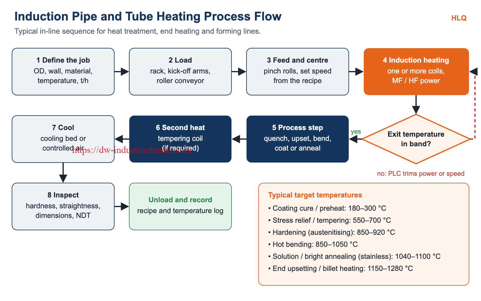
| 1 | Define OD, wall, material, temperature and throughput | Power and frequency sized |
| 2 | Load pipes from the rack onto the roller conveyor | Straightness, clean surface |
| 3 | Feed and centre through pinch rolls at the recipe speed | Concentric in the coil |
| 4 | Induction heating in one or more coils | Exit temperature by pyrometer |
| 5 | Process step: quench, upset, bend, coat or anneal | Process parameters |
| 6 | Second heat (tempering coil) if required | Tempering temperature |
| 7 | Cool on the cooling bed or in controlled air | Cooling rate |
| 8 | Inspect and unload; log the recipe and temperatures | Hardness, dimensions, NDT |
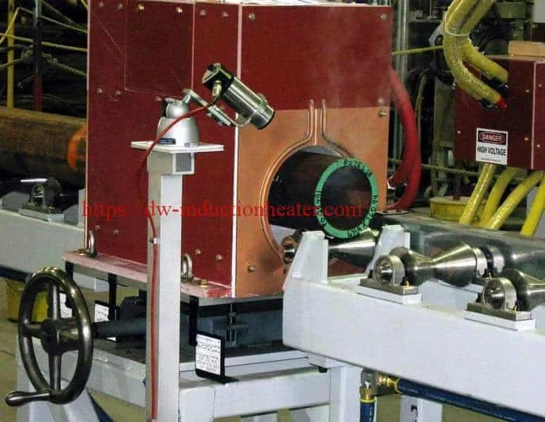
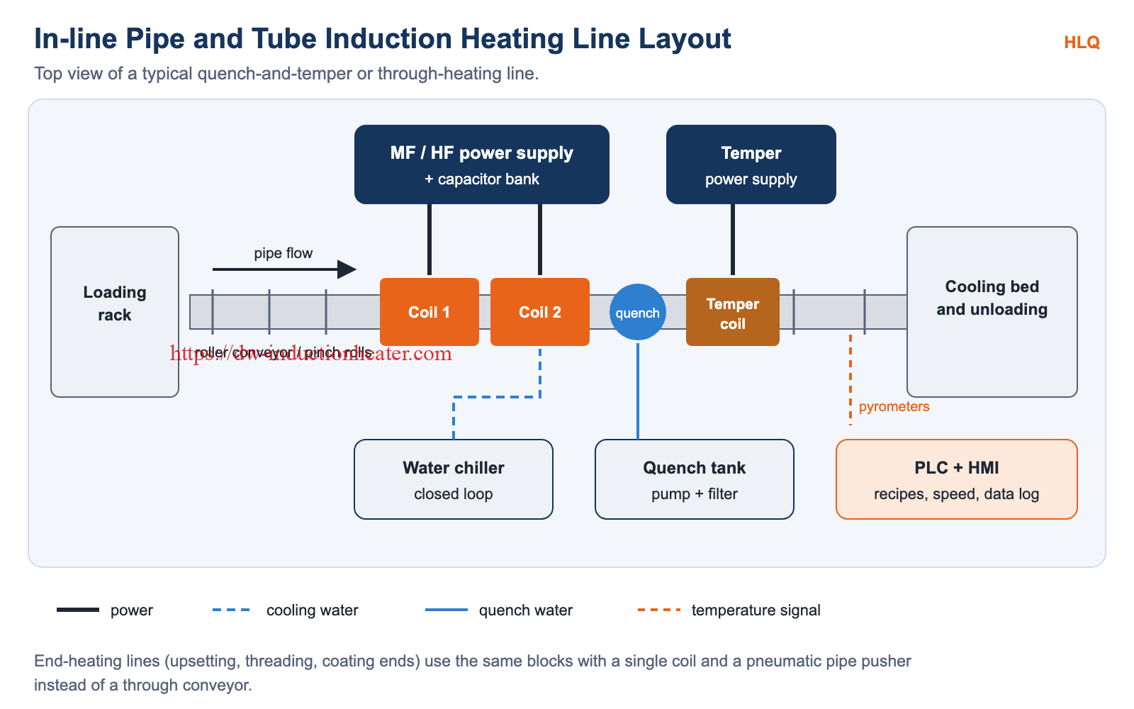
Typical line layout

Common Problems and Solutions
| Problem | Likely cause | Solution |
|---|---|---|
| Uneven temperature around the pipe | Pipe off-centre in the coil; ovality | Centre with guide rolls; reduce the air gap variation |
| Surface overheats, core stays cold | Frequency too high for the wall | Lower the frequency or add a soak zone |
| Power drops above ≈ 770 °C | Curie point: steel becomes non-magnetic | Use a second coil tuned for the hot stage |
| Hot ends or cold ends | End effect as the pipe enters and leaves the coil | Adjust speed at the ends; use butted pipes for continuous feed |
| Hardness scatter after Q&T | Temperature or quench variation | Closed-loop pyrometer control; check the quench flow |
| Coil damage | Insufficient cooling water or pipe contact | Check flow and temperature; fit coil guards |
| Coating defects | Wrong cure temperature or dwell time | Set the exit temperature to the coating datasheet; see induction pipeline coating heating |
Engineering Selection Guide
| Factor | Question to answer | Guideline |
|---|---|---|
| Wall thickness | How thick is the wall? | Select the frequency from the skin-depth table |
| Throughput | How many t/h or pieces per hour? | Size the power with P = ṁ · Δh / η |
| Temperature | Below or above 770 °C? | Above the Curie point, plan two stages or a lower frequency |
| Heated zone | Full length, end or band? | Through, end-heating or narrow-band coil |
| Diameter range | How many sizes? | Each coil covers a range; plan coil changes |
| Atmosphere | Bright surface needed? | Use a protective gas muffle for stainless bright annealing |
| Fluid heating | Heating the fluid inside, not the pipe? | See the induction thermal fluid pipeline heater |
Advantages and Limitations
| Advantages | Limitations |
|---|---|
| Heats only the pipe; no furnace losses (60–83 % overall efficiency) | Coils are matched to diameter ranges |
| Fast start-up, 100 % duty cycle | Higher investment than a gas furnace for low volumes |
| ±3–5 °C control and data logging | Lower efficiency above the Curie point |
| Compact in-line footprint | Needs closed-loop cooling water and a strong power supply |
| Clean, flame-free, little scale | Bright annealing still needs protective gas |
Why Choose HLQ?
| Strength | What it means for you |
|---|---|
| 25–500 kW MF range | One supplier from small tube to large pipe |
| Engineered coils | Encircling, end-heating and narrow-band designs |
| Line integration | Conveyors, pyrometers, quench and PLC recipes |
| Continuous duty | 100 % duty cycle with closed-loop cooling |
| Application testing | Process proven on your pipe before delivery |
10 Core FAQs
1. What is an induction pipe and tube heating system?
A power supply, coil and controls that heat the pipe wall directly by electromagnetic induction, either in-line or at the pipe end.
2. Which frequency should I choose?
Choose by wall thickness: 30–100 kHz for walls up to 3 mm, 10–30 kHz for 3–6 mm, 3–10 kHz for 6–12 mm, 1–3 kHz for 12–25 mm, and 0.5–1 kHz for thicker walls.
3. How much power do I need?
P = throughput × enthalpy ÷ efficiency. For example, 1 t/h of steel heated to 1000 °C needs about 290 kW at 65 % efficiency.
4. What pipe sizes can be heated?
The standard MF-25 to MF-500 range covers Ø20–1500 mm and walls from 2 to 100 mm. Larger sizes are built to order.
5. How accurate is temperature control?
±3–5 °C with pyrometer feedback, with the PLC adjusting power or line speed.
6. Why does heating slow down above about 770 °C?
Steel loses its magnetism at the Curie point, so the skin depth grows and coupling drops. A second coil or a lower frequency handles the hot stage.
7. Can the system heat only the pipe end?
Yes. End-heating coils heat a set length for upsetting, swage-end stress relief, threading or tool-joint preheat.
8. Is protective gas required?
Only for bright annealing of stainless steel. Most other processes run in air.
9. Can the same system bend pipe?
Bending uses a narrow-band coil and a bending machine. See the induction pipe bending machine.
10. Is induction more efficient than a gas furnace?
Usually, yes. Overall efficiency is 60–83 % with no furnace wall losses, starts are instant, and only the required zone is heated.
Related products
-

IGBT PWHT machine with DSP and PLC control
-
60kw Induction Heater-Induction Heating Equipment
-
Induction Heating titanium and stainless steel for hot heading
-
Induction Heating for Disassembly and Assembly large bearings, shaft couplings, propeller hubs and Turbine Bearings in Shipbuilding Industry and Heavy Machinery Maintenance
-
induction heating stainless steel insertion application