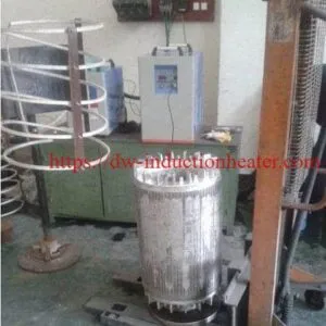

Shrink Fitting Stator and Rotor With Induction
Induction Shrink Fitting Stator and Rotor With High Frequency Heating Equipment
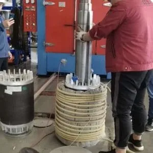
Shrink fitting stators and rotors with induction heating is a precision assembly process used in electric motor manufacturing, motor repair, generator assembly, EV motor production, pump motors, servo motors, traction motors, and industrial rotating equipment. The process uses controlled electromagnetic induction heating to expand a metal component—such as a stator housing, rotor core, rotor sleeve, bearing seat, or shaft coupling—so that another component can be inserted without excessive mechanical force. After cooling, the heated component contracts and forms a strong interference fit.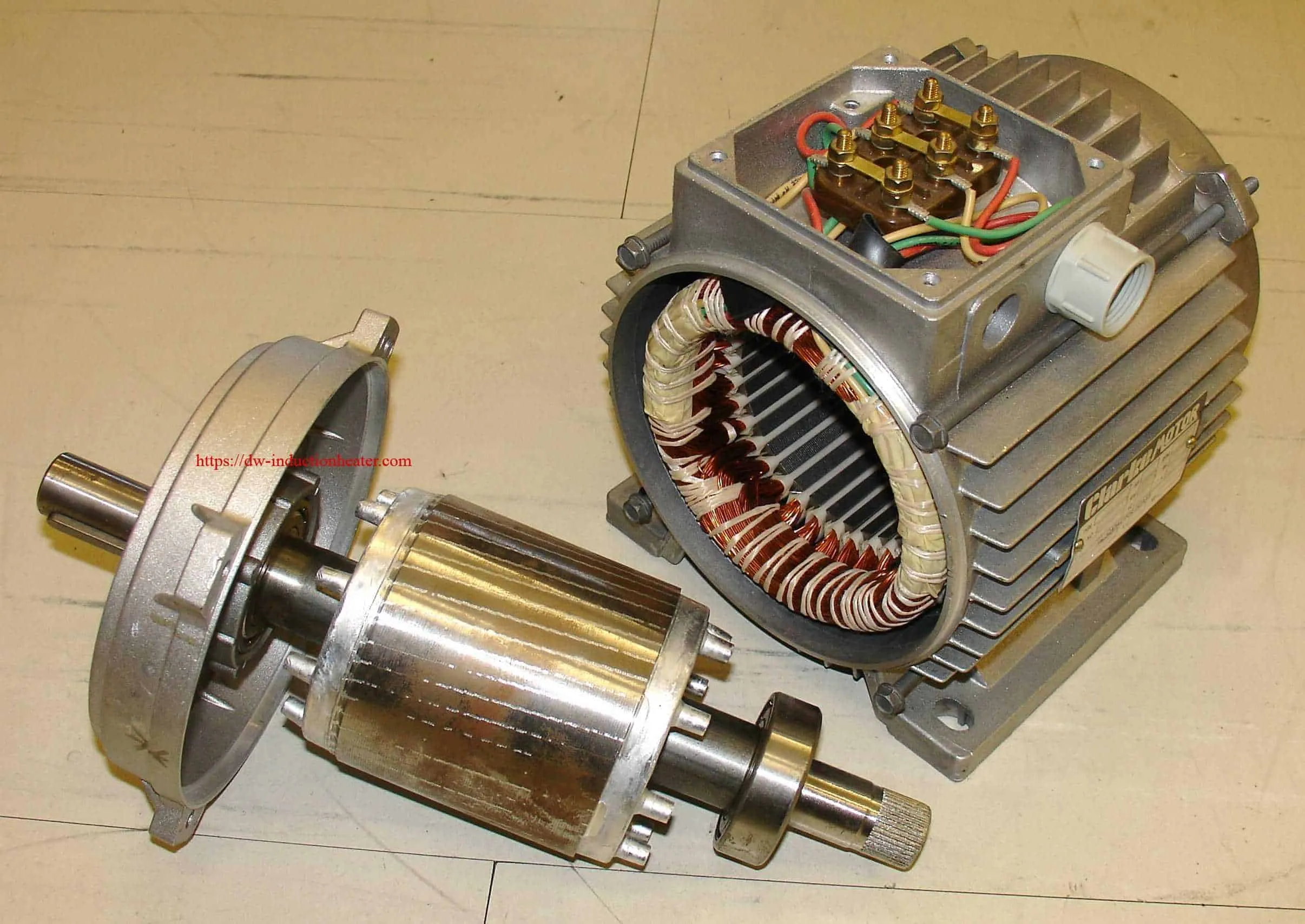
Induction shrink fitting is widely used because it provides fast heating, clean operation, accurate temperature control, localized heating, repeatable assembly quality, and reduced mechanical damage compared with flame heating, ovens, or press-only assembly. Industry sources describe induction shrink fitting as a controlled method that uses thermal expansion for assembly or removal, with advantages including efficiency, localized heating, controllability, and traceability.
1. What Is Induction Shrink Fitting?
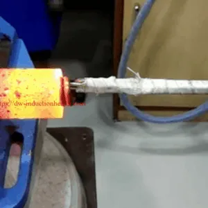
Induction shrink fitting uses an induction coil to generate an alternating magnetic field. When a conductive metal part is placed inside or near the coil, eddy currents are induced inside the metal. These currents create heat directly inside the component.
For stator and rotor assembly, the heated part expands slightly. This temporary expansion allows a shaft, housing, sleeve, bearing, or rotor core to be inserted. When the part cools, it contracts and creates a tight mechanical bond.
Typical heated components include:
|
Application |
Heated Part |
Inserted Part |
|---|---|---|
|
Stator into motor housing |
Motor housing |
Stator core |
|
Rotor core onto shaft |
Rotor laminated core |
Rotor shaft |
|
Bearing mounting |
Bearing inner ring |
Motor shaft |
|
Sleeve fitting |
Rotor sleeve |
Rotor core |
|
Coupling assembly |
Coupling hub |
Shaft |
|
Generator assembly |
Rotor or stator component |
Shaft or housing |
Induction shrink fitting is especially suitable for cylindrical or ring-shaped parts, including bearings, gears, motor stators, motor shafts, rotors, couplings, and precision mechanical components.
2. Why Use Induction Heating for Stator and Rotor Shrink Fitting?
Compared with oven heating, flame heating, oil bath heating, or cold pressing, induction heating gives better control over the temperature and heating zone.
Main Advantages
|
Advantage |
Engineering Value |
|---|---|
|
Fast heating |
Shorter assembly cycle time |
|
Localized heating |
Heat only the required area, reducing distortion |
|
Non-contact heating |
No flame, no contamination, no direct tool wear |
|
Accurate temperature control |
Prevents overheating of laminations, insulation, magnets, or bearings |
|
High repeatability |
Suitable for automated motor production lines |
|
Energy efficiency |
Energy is delivered directly into the workpiece |
|
Cleaner workshop |
No gas flame, oil smoke, soot, or open fire |
|
Better assembly quality |
Reduces hammering, pressing damage, and misalignment |
Induction heating can heat only the required region instead of heating an entire casting or motor component, which helps reduce distortion and protect machined surfaces.
3. Typical Process Flow
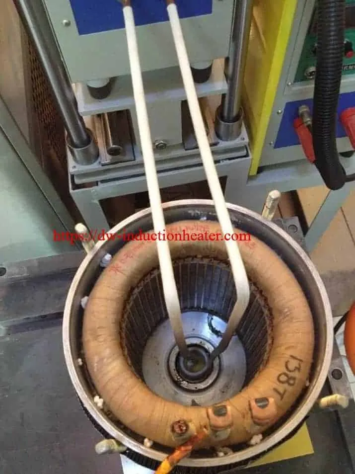
Induction Shrink Fitting Process for Rotor Core and Shaft
- Clean the mating surfaces
Remove oil, rust, burrs, oxide scale, and metal chips. - Measure interference allowance
Confirm shaft diameter, bore diameter, roundness, and tolerance. - Load the rotor core into the induction coil
The rotor core should be centered inside the coil.
- Set heating temperature
Typical shrink fitting temperatures are often in the range of 150°C–300°C, depending on material, interference amount, and part geometry. - Heat the rotor core uniformly
Use temperature feedback by infrared pyrometer or thermocouple. - Insert the shaft quickly and coaxially
Use a guide fixture, hydraulic slide, servo press, or vertical assembly jig. - Hold during cooling
Maintain alignment until the interference fit locks. - Inspect runout and position
Check axial position, concentricity, end face runout, and rotor balance.
4. Typical Technical Parameters
|
Item |
Typical Range / Recommendation |
|---|---|
|
Heating method |
Medium-frequency or high-frequency induction heating |
|
Common power range |
10–300 kW, depending on part size |
|
Frequency range |
1–30 kHz for larger parts; 30–100 kHz for smaller/localized heating |
|
Heating temperature |
150–300°C for many shrink-fit assemblies |
|
Temperature control |
Infrared pyrometer, thermocouple, PLC closed-loop control |
|
Heating time |
20 seconds to several minutes |
|
Coil type |
Internal coil, external coil, split coil, customized contour coil |
|
Cooling method |
Natural cooling or controlled air cooling |
|
Assembly method |
Manual fixture, hydraulic press, servo press, robotic loading |
|
Suitable materials |
Carbon steel, alloy steel, cast iron, stainless steel, electrical steel laminations |
5. Coil Design for Stator and Rotor Shrink Fitting
Coil design is critical. A poor coil can cause uneven expansion, local overheating, poor concentricity, or assembly failure.
Common Coil Types
|
Coil Type |
Best For |
Notes |
|---|---|---|
|
External circular coil |
Heating outer ring, housing, rotor core OD |
Simple and common |
|
Internal bore coil |
Heating inner bore of stator housing or rotor core |
Useful when expansion of bore is required |
|
Split induction coil |
Large parts or parts that cannot be loaded axially |
Easy loading/unloading |
|
Multi-turn solenoid coil |
Uniform heating of cylindrical parts |
Suitable for rotor cores and sleeves |
|
Profile coil |
Complex geometry |
Designed according to heating zone |
For a rotor core installed onto a shaft, the coil usually heats the rotor core bore area or full rotor core body. For stator insertion into a housing, the coil usually heats the motor housing so the stator can be inserted with minimal force.
6. Key Engineering Points
6.1 Control the Temperature Carefully
Overheating may damage: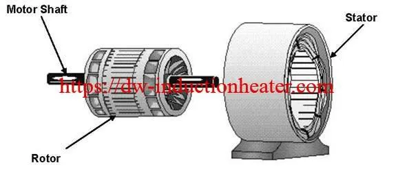
- Electrical steel laminations
- Insulation coating
- Permanent magnets
- Bearing grease
- Adhesives or resin
- Precision-machined surfaces
For laminated rotor cores, excessive mechanical contact during shaft insertion can also deform the lamination edges or cause misalignment; patent literature on laminated rotor shrink fitting specifically discusses the need to reduce deformation and misalignment during shaft insertion.
6.2 Ensure Uniform Expansion
Uniform heating is more important than maximum temperature. If one side expands more than the other, the shaft may jam during insertion.
Recommended controls:
- Use a coaxial fixture
- Rotate the part during heating if needed
- Use multi-point temperature monitoring
- Avoid excessive heating at sharp edges
- Design the coil according to the part geometry
6.3 Use Proper Assembly Fixtures
A good shrink fitting station should include:
|
Fixture Component |
Function |
|---|---|
|
Centering cone |
Keeps shaft and rotor coaxial |
|
Vertical guide rail |
Prevents angular insertion |
|
Servo or hydraulic pusher |
Controls insertion speed |
|
Position stop |
Controls final axial location |
|
Temperature sensor |
Confirms assembly-ready condition |
|
Safety shield |
Protects operator from hot parts |
7. Recommended Equipment Configuration
A complete induction shrink fitting system for stator and rotor assembly can include:
|
Equipment |
Function |
|---|---|
|
Induction heating power supply |
Provides controlled AC power |
|
Water-cooled induction coil |
Generates magnetic field |
|
Cooling water system |
Cools coil and power supply |
|
PLC control cabinet |
Stores heating recipes |
|
Infrared temperature sensor |
Measures part temperature |
|
Touchscreen HMI |
Operator parameter setting |
|
Assembly press or fixture |
Inserts shaft/stator/housing |
|
Loading platform |
Supports heavy components |
|
Safety guard |
Operator protection |
|
Data logging system |
Records temperature, time, power, batch data |
8. Example Process Parameters
Example: Rotor Core Shrink Fit Onto Motor Shaft
|
Parameter |
Example Value |
|---|---|
|
Rotor core material |
Laminated silicon steel |
|
Shaft material |
Alloy steel |
|
Rotor OD |
180 mm |
|
Rotor bore |
55 mm |
|
Interference allowance |
0.03–0.08 mm |
|
Heating temperature |
180–230°C |
|
Induction power |
25–60 kW |
|
Frequency |
10–30 kHz |
|
Heating time |
45–120 seconds |
|
Assembly method |
Vertical guided insertion |
|
Quality check |
Runout, axial position, torque retention |
Example: Stator Shrink Fit Into Motor Housing
|
Parameter |
Example Value |
|---|---|
|
Housing material |
Aluminum or cast iron |
|
Stator OD |
220 mm |
|
Housing bore |
Interference-fit tolerance |
|
Heating temperature |
120–250°C depending on material |
|
Induction power |
30–100 kW |
|
Coil type |
External or internal bore coil |
|
Assembly method |
Servo press or pneumatic/hydraulic insertion |
|
Inspection |
Concentricity, stator position, housing deformation |
9. Common Problems and Solutions
|
Problem |
Possible Cause |
Solution |
|---|---|---|
|
Shaft cannot be inserted |
Temperature too low or interference too large |
Increase heating temperature or adjust tolerance |
|
Rotor jams halfway |
Poor alignment or uneven heating |
Improve guide fixture and coil uniformity |
|
Excessive runout |
Coaxiality error during insertion |
Use precision positioning fixture |
|
Lamination deformation |
Excessive insertion force |
Increase thermal clearance and reduce pressing force |
|
Overheated surface |
Coil too close or frequency too high |
Optimize coil distance and frequency |
|
Insulation damage |
Temperature too high |
Use closed-loop temperature control |
|
Long cycle time |
Power too low or poor coupling |
Increase power or redesign coil |
|
Poor repeatability |
Manual operation variation |
Use PLC recipes and automatic loading |
10. Quality Control Checklist
Before production:
- Confirm shaft and bore dimensions
- Confirm interference tolerance
- Test heating uniformity
- Verify temperature sensor accuracy

- Check fixture coaxiality
- Validate heating time and insertion time
- Record cooling time and final retention strength

After assembly:
- Check axial position
- Check radial runout
- Check end face runout
- Check rotor balance
- Check insulation condition
- Check torque transmission strength
- Record batch parameters
11. Best Applications
Induction shrink fitting is suitable for:
- EV motor rotor assembly
- Industrial motor stator assembly
- Servo motor production
- Generator rotor assembly
- Pump motor repair
- Compressor motor assembly
- Railway traction motors
- Wind generator components
- Bearing mounting and removal
- Coupling and gear fitting
12. Conclusion
Induction heating is one of the best methods for shrink fitting stators and rotors because it provides fast, localized, controllable, repeatable, and clean heating. For electric motor manufacturing, it can improve assembly accuracy, reduce mechanical damage, shorten cycle time, and support automation.
For best results, the system should be designed around the actual part size, material, interference allowance, heating temperature, required cycle time, and assembly accuracy. The most important engineering factors are coil design, temperature control, uniform expansion, coaxial fixture design, and process repeatability.

Related products
-

Induction aluminum billet preheat furnaces for forging extrusion and forming applications
-
induction heating bore of steel pipe
-
Heating Shrink Fitting Machine
-
Induction thermal for the expansion and removal of large bearings, shafts and couplings for turbines and generators
-
what is induction shrink fitting