
Induction Shrink Fitting
Induction Shrink Fitting Machine for Gears, Bearings & Couplings
Quick Answer: What Is an Induction Shrink Fitting Machine?
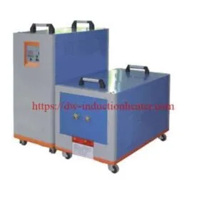
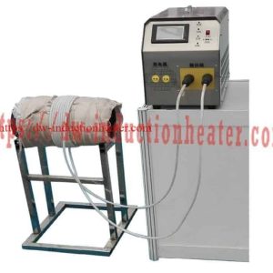
An induction shrink fitting machine is an industrial heating system used to expand metal components temporarily for precision interference-fit assembly or thermal disassembly. The equipment uses electromagnetic induction to heat gears, bearings, rings, sleeves, couplings, hubs, and other conductive metal components without direct contact with a flame or heating element.
When the outer component is heated, its internal diameter increases through thermal expansion. This allows a shaft or mating component to be inserted with temporary clearance. As the heated component cools, it contracts and creates the designed interference fit.
HLQ induction shrink fitting systems can be configured using medium-frequency (MF), high-frequency (HF), or ultra-high-frequency (UHF) induction heating equipment. The most suitable system depends on the workpiece material, dimensions, required temperature, interference allowance, heating time, and production capacity.
| Key Parameter | Engineering Description |
|---|---|
| Equipment | Induction Shrink Fitting Machine |
| Heating Method | Electromagnetic induction heating |
| Main Applications | Gears, bearings, shafts, sleeves, couplings, hubs, flanges, rotors, and stator assemblies |
| Suitable Materials | Carbon steel, alloy steel, stainless steel, cast iron, aluminum alloys, and selected copper alloys |
| Heating Temperature | Determined by material properties, interference allowance, and permissible component temperature |
| Frequency Selection | MF, HF, or UHF according to workpiece geometry and heating requirements |
| Power Selection | Determined by component mass, temperature rise, required cycle time, and heating efficiency |
| Heating Control | Adjustable power and heating time; temperature monitoring can be integrated |
| Cooling | Equipment-dependent; water-cooled induction systems are commonly used |
| Production Configuration | Manual workstation, semi-automatic station, or customized production line |
Engineering Note: The original product description discusses temperatures of approximately 150–300°C. This is not a universal operating range. The required temperature must be calculated for each application, and the component’s metallurgical temperature limit must be respected.
What Is an Induction Shrink Fitting Machine?
An induction shrink fitting machine is a specialized metal heating system designed to facilitate the assembly and disassembly of precision mechanical components through controlled thermal expansion.
Shrink fitting is widely used in industrial manufacturing because it creates a mechanical connection without requiring adhesives, welding, or permanent fasteners.
The process is based on an interference fit. At the reference temperature, the outside diameter of the shaft is slightly larger than the inside diameter of the component to be installed.
Heating the outer component causes its bore to expand. Once sufficient clearance is created, the shaft can be inserted. After cooling, the outer component contracts around the shaft.
What Is the Difference Between Shrink Fitting and Press Fitting?
| Comparison | Induction Shrink Fitting | Mechanical Press Fitting |
|---|---|---|
| Assembly Principle | Temporary thermal expansion | Mechanical insertion force |
| Heating Required | Yes | Usually no |
| Assembly Force | Can be substantially reduced | Depends on interference and friction |
| Surface Damage Risk | Reduced sliding damage when adequate clearance is achieved | Possible galling or scoring |
| Temperature Control | Required | Usually not required |
| Equipment Requirements | Induction heater, coil, temperature monitoring, and assembly fixture | Mechanical or hydraulic press |
| Typical Applications | Gears, couplings, hubs, bearing rings, and sleeves | Bushings, pins, sleeves, and other press-fit components |
The final choice between thermal assembly and mechanical pressing depends on component geometry, surface condition, interference tolerance, available assembly force, and production requirements.
Key Applications of Induction Shrink Fitting Machines
Induction shrink fitting is widely used in mechanical engineering, automotive manufacturing, electric motors, power generation, mining machinery, and industrial equipment maintenance.
1. Induction Shrink Fitting of Gears onto Shafts
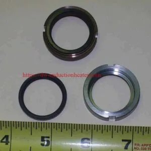
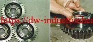
Steel gears, camshaft gears, spur gears, and transmission gears can be heated around their bores before installation onto shafts.
Controlled heating reduces the mechanical force required during assembly and helps protect precision-machined mating surfaces.
For practical application examples, see induction shrink fitting of shaft gears.
2. Bearing Installation and Removal
Induction heating can expand suitable bearing rings or housings to assist bearing mounting and removal.
For complete rolling-element bearings, heating conditions must follow the bearing manufacturer’s instructions. Excessive temperature can damage seals, lubricants, cages, or heat-treated components.
3. Coupling and Hub Assembly
Industrial couplings and hubs are often mounted onto shafts using interference fits.
Induction heating provides a controlled method of expanding the hub before assembly.
Typical applications include:
- Industrial drive couplings
- Heavy-duty motor couplings
- Generator shaft couplings
- Gearbox components
- Power transmission hubs
4. Steel Flange and Ring Assembly
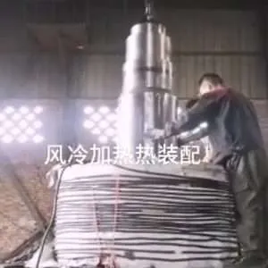
Large steel rings and flanges can be heated to increase their internal diameters before installation onto cylindrical mating components.
The process may reduce mechanical assembly forces and the risk of surface damage when the expansion is sufficiently uniform.
Additional information is available in the induction heating shrink fitting of steel flanges application.
5. Electric Motor Rotor and Stator Assembly
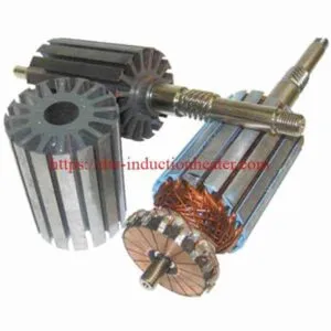
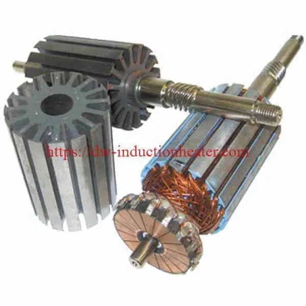
Induction heating may be used when assembling selected motor housings, rotor hubs, shafts, and related metallic components.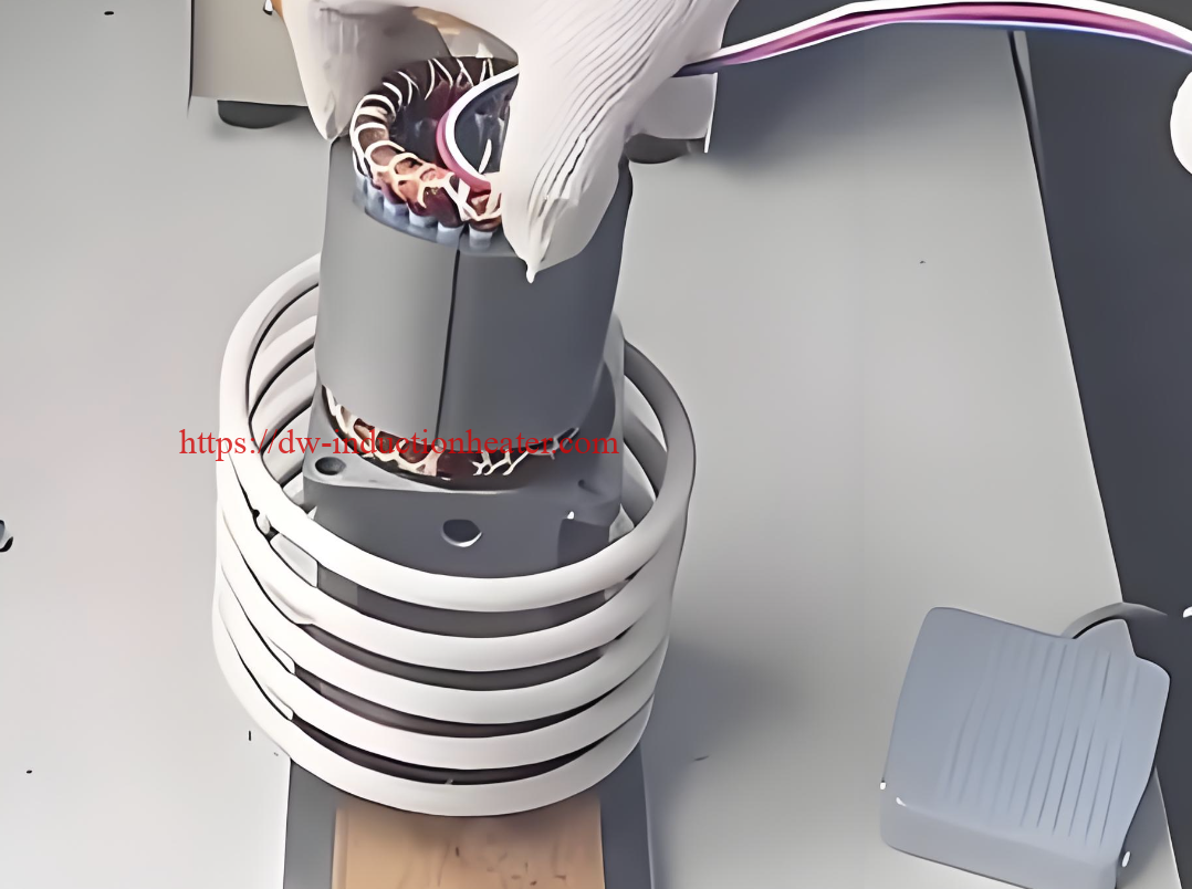
Temperature-sensitive insulation, magnets, adhesives, and other motor components must be protected.
6. Industrial Thermal Disassembly
Controlled heating of the surrounding metal component can create differential expansion and assist the removal of tightly fitted mechanical parts.
This approach is particularly useful when mechanical extraction force alone is insufficient or could damage the assembly.
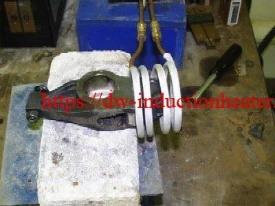
Application Overview
| Application | Typical Component | Main Engineering Requirement |
|---|---|---|
| Gear Assembly | Steel or alloy-steel gear | Uniform bore expansion and gear hardness protection |
| Bearing Mounting | Bearing ring or bearing assembly | Temperature control and dimensional accuracy |
| Coupling Assembly | Steel hub or coupling | Adequate thermal clearance and fast positioning |
| Shaft Sleeve Assembly | Steel or stainless steel sleeve | Controlled interference and surface protection |
| Motor Assembly | Rotor hub, housing, or stator-related component | Protection of temperature-sensitive components |
| Thermal Disassembly | Coupling, ring, or housing | Differential expansion and controlled extraction |
Suitable Materials for Induction Shrink Fitting
Most electrically conductive metals can be heated by induction. However, electrical conductivity, magnetic permeability, thermal conductivity, and component geometry significantly affect heating behavior.
Ferromagnetic steels usually couple strongly with an induction field below their Curie temperature. Nonmagnetic materials, including aluminum and austenitic stainless steel, require appropriate coil and frequency selection.
Typical Thermal Expansion Coefficients
| Material | Approximate Linear Expansion Coefficient (10⁻⁶/K) | Engineering Considerations |
|---|---|---|
| Carbon Steel | 11–13 | Check material grade and heat-treatment condition |
| Alloy Steel | Approximately 11–14 | Verify the actual alloy and heat-treatment limits |
| 304 / 316 Austenitic Stainless Steel | Approximately 16–18 | Nonmagnetic or weakly magnetic conditions can affect heating |
| Aluminum Alloys | 21–24 | High thermal conductivity and temper sensitivity |
| Cast Iron | 10–12 | Check brittleness, material grade, and thermal stress |
| Brass | 18–21 | Expansion and heating response depend on alloy composition |
| Copper | Approximately 16–17 | High electrical and thermal conductivity require optimized coupling |
Important: These coefficients are approximate reference values, not certified properties for a specific grade. Actual thermal expansion changes with temperature and alloy composition.
Material Compatibility and Heating Precautions
| Material | Induction Heating Suitability | Special Precautions |
|---|---|---|
| Carbon Steel | Generally suitable | Avoid exceeding relevant tempering or stress-relief limits |
| Hardened Tool Steel | Suitable under controlled conditions | Protect hardness and dimensional stability |
| Stainless Steel | Suitable with matched equipment | Account for magnetic and nonmagnetic grades |
| Aluminum Alloys | Suitable with optimized coil coupling | Check allowable temperature and alloy temper |
| Cast Iron | Potentially suitable | Avoid excessive thermal gradients and cracking |
| Copper Alloys | Suitable in selected applications | Power and frequency matching are important |
Working Principle of Induction Shrink Fitting
An induction shrink fitting machine uses alternating electrical current flowing through an induction coil to generate a changing magnetic field.
When a conductive metal component is positioned inside or near the coil, the changing magnetic field induces electrical currents within the component.
The induced currents produce heat through electrical resistance. In ferromagnetic materials, magnetic losses may also contribute under suitable operating conditions.
The heated component expands according to its thermal expansion characteristics.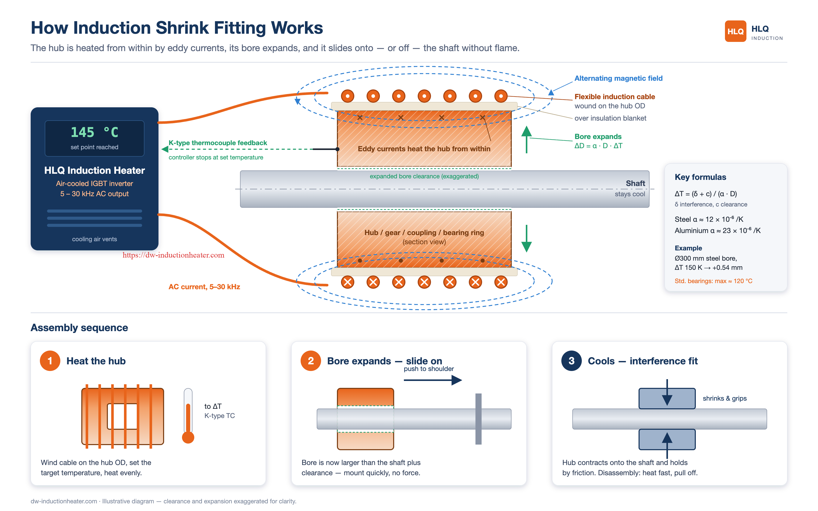
Three Main Stages
- Induction Heating: The outer component is heated to the required temperature.
- Thermal Expansion: The internal diameter increases sufficiently to create installation clearance.
- Cooling and Interference Fit: The component is assembled and contracts during cooling to create the designed mechanical fit.
Thermal Expansion Formula
For a first-pass calculation under approximately uniform heating:
ΔD = α × D × ΔT
Where:
- ΔD = change in bore diameter, mm
- α = linear thermal expansion coefficient, 1/K
- D = initial bore diameter, mm
- ΔT = temperature rise, K or °C
Example: Steel Sleeve Expansion
Consider a steel sleeve with the following dimensions:
| Parameter | Value |
|---|---|
| Initial Bore Diameter | 80 mm |
| Material | Carbon steel |
| Assumed Expansion Coefficient | 12 × 10⁻⁶/K |
| Initial Temperature | 25°C |
| Temperature Rise | 120°C |
Calculated expansion:
ΔD = 12 × 10⁻⁶ × 80 × 120
ΔD ≈ 0.115 mm
Therefore, heating the steel sleeve uniformly by 120°C increases its theoretical bore diameter by approximately 0.115 mm.
This calculation assumes uniform temperature and unconstrained thermal expansion. Actual assembly behavior may differ because of temperature gradients, contact conditions, and component geometry.
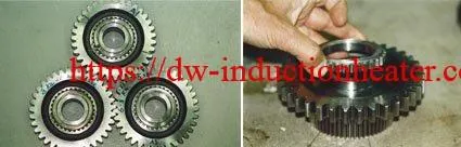
Induction Shrink Fitting vs. Thermal Disassembly
The same thermal expansion principle can also assist disassembly.
For assembly, the outer component is heated sufficiently to permit insertion. For disassembly, controlled differential expansion can reduce the grip on the inner component.
Learn more about induction shrink fitting and thermal disassembly for industrial maintenance applications.
Technical Specifications of Induction Shrink Fitting Systems
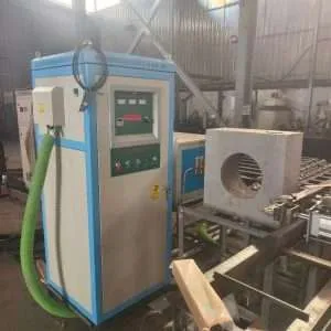
HLQ induction shrink fitting systems may use different induction generator series depending on the required component size and heating performance.
The original Induction Shrink Fitting product page does not provide a dedicated machine nameplate or model-specific technical datasheet. The following specifications distinguish general system configuration requirements from parameters published for related HLQ induction power supplies.
General System Configuration
| Technical Item | Configuration / Engineering Requirement |
|---|---|
| System Type | IGBT-based solid-state induction heating system or other application-specific induction heating configuration |
| Heating Process | Controlled induction heating for interference-fit assembly |
| Heating Components | Metal rings, gears, sleeves, hubs, couplings, and suitable bearing-related components |
| Heating Power | Selected according to workpiece mass, temperature rise, and cycle time |
| Operating Frequency | Selected according to generator series, material, and coil coupling |
| Power Control | Adjustable according to the selected power supply |
| Temperature Monitoring | Thermocouple or infrared measurement, subject to application requirements |
| Induction Coil | Custom-designed according to component dimensions and heating zone |
| Cooling | Water cooling where required by the generator and coil design |
| Automation | Optional fixture, positioning, handling, and process monitoring integration |
| Safety Requirements | Electrical protection, suitable cooling interlocks, and safe handling of heated parts |
Published HLQ Power Supply Examples
| Model | Published Power Rating | Published Frequency | Electrical Supply | Selection Notes |
|---|---|---|---|---|
| DW-HF-15 | 15 kW maximum output | 10–80 kHz | Single-phase 220 V | Candidate for smaller components and localized heating |
| DW-HF-25KW-B | 25 kVA rated value | 30–80 kHz | Three-phase 380 V | Candidate for small and medium-size components |
| DW-MF-35 | 35 kW maximum input power | 1–20 kHz | Three-phase 380 V | Candidate for medium components requiring greater heating depth |
| DW-MF-70 | 70 kW maximum input power | 1–20 kHz | Three-phase 380 V | Candidate for larger components and higher thermal loads |
| DW-MF-110 | 110 kW maximum input power | 1–20 kHz | Three-phase 380 V | Candidate platform for larger industrial applications |
Specification Clarification: kVA and kW are not interchangeable. Published input power is also different from electrical output power and heat actually absorbed by the workpiece.
The models above are examples from related HLQ product information. They are not confirmed model specifications of the original Induction Shrink Fitting product listing.
Actual equipment selection, coil compatibility, duty cycle, cooling requirements, and available voltage configurations must be verified for the intended application.
Recommended Induction Shrink Fitting Machine Model Selection
Induction shrink fitting equipment should be selected according to the workpiece, not simply according to the maximum rated power of the generator.
Four primary factors determine the initial selection:
- Workpiece material and electrical properties
- Component diameter, wall thickness, and total mass
- Required temperature rise and heating uniformity
- Production cycle time and operating duty
Preliminary Equipment Selection Guide
| Application | Possible HLQ Platform | Engineering Selection Reason | Verification Requirement |
|---|---|---|---|
| Small steel rings and gears | DW-HF-15 | Localized heating with an appropriate HF coil | Confirm bore temperature and heating uniformity |
| Small and medium steel sleeves | DW-HF-25KW-B | Higher published electrical capacity than the HF-15 platform | Confirm actual kW output and coil matching |
| Medium-size steel hubs | DW-MF-35 | Lower-frequency platform for increased heating penetration | Confirm mass, heating time, and temperature gradients |
| Large couplings and rings | DW-MF-70 | Higher-power MF platform for larger thermal loads | Verify heating uniformity and cooling capacity |
| Heavy industrial assemblies | DW-MF-110 or engineered alternative | Higher electrical capacity for demanding heating applications | Complete thermal calculation and production trials |
| Small precision gear bores | Application-matched UHF system | Localized heating with a suitable coil geometry | Verify frequency, temperature distribution, and material limits |
The listed configurations are candidate selections rather than guaranteed workpiece capacities.
For additional power supply information, refer to HLQ industrial induction heating power supplies.
Published Gear Shrink Fitting Examples
HLQ has published induction shrink-fitting examples involving steel and aluminum camshaft gears.
| Parameter | Steel Gear Example | Aluminum Gear Example |
|---|---|---|
| Gear Diameter | 6 inches | 6 inches |
| Gear Thickness | 2 inches | 2 inches |
| Published Power Supply | DW-UHF-3.5 kW | DW-UHF-3.5 kW |
| Published Frequency | 151 kHz | 158 kHz |
| Reported Temperature | 518°F / approximately 270°C | 320°F / approximately 160°C |
| Reported Heating Time | 3 minutes | 4 minutes |
These are historical published application examples, not guaranteed performance figures for newly supplied equipment. Production results depend on coil geometry, component mass, coupling efficiency, and process conditions.
The historical DW-UHF-3.5 example should not be interpreted as confirmation of current model availability.
Induction Shrink Fitting Process Workflow
A successful induction shrink fitting process requires accurate dimensional measurements, controlled heating, suitable handling equipment, and repeatable assembly procedures.
Step 1: Inspect the Components
Measure the shaft diameter and component bore at a defined reference temperature.
Confirm the specified interference fit, dimensional tolerance, surface finish, and alignment requirements.
Step 2: Calculate Required Thermal Expansion
Determine the minimum required bore expansion from the diametral interference and the desired assembly clearance.
Step 3: Select the Induction Coil
Design or select a coil that provides suitable electromagnetic coupling and heating distribution.
Common configurations include external helical coils, internal coils, and customized coils for irregular component geometry.
Step 4: Position the Workpiece
Place the component in the induction heating station using a suitable fixture.
Maintain the required coil-to-workpiece clearance.
Step 5: Apply Controlled Induction Heating
Set the power and heating time based on the validated process.
Monitor the relevant component temperature and avoid overheating or excessive temperature gradients.
Step 6: Assemble the Components
After the required expansion is achieved, move the heated component into position and insert the shaft or mating component.
Assembly must be completed within the validated temperature and time window.
Step 7: Allow Controlled Cooling
Support the assembly as required while the heated component cools and contracts.
Avoid uncontrolled quenching unless specifically required by an approved process.
Step 8: Inspect the Final Assembly
Check alignment, runout, final dimensions, and any required mechanical acceptance criteria.
The same general engineering approach can be adapted for induction heating for stator and rotor assembly, provided temperature-sensitive motor components are protected.

Process Control Checklist
| Process Stage | Critical Control Parameter | Recommended Verification |
|---|---|---|
| Before Heating | Actual interference allowance | Dimensional measurement |
| Coil Positioning | Coil clearance and alignment | Fixture inspection |
| Heating | Temperature and heating time | Suitable calibrated temperature measurement |
| Assembly | Insertion clearance and alignment | Assembly observation and position verification |
| Cooling | Component stability and cooling conditions | Process monitoring |
| Final Inspection | Fit accuracy and component condition | Dimensional and mechanical inspection |
Common Problems and Solutions in Induction Shrink Fitting
Heating speed alone does not determine the success of a shrink fitting process. Temperature uniformity, mechanical tolerances, assembly handling, and coil matching are equally important.
| Problem | Possible Cause | Recommended Solution |
|---|---|---|
| Insufficient Bore Expansion | Temperature too low or incorrect interference calculation | Recalculate required expansion and verify bore temperature |
| Uneven Heating | Incorrect coil geometry or poor coupling | Optimize coil position, winding arrangement, and part rotation where suitable |
| Long Heating Time | Insufficient effective power or poor coil matching | Evaluate actual power transfer, frequency, and component thermal mass |
| Component Distortion | Excessive temperature gradients or overheating | Improve heating uniformity and validate temperature limits |
| Assembly Cannot Be Completed | Insufficient clearance, misalignment, or excessive transfer delay | Increase validated clearance and improve handling procedures |
| Surface Discoloration | Excessive surface temperature or extended heating | Adjust power distribution and temperature control |
| Inconsistent Batch Results | Changes in workpiece positioning, initial temperature, or geometry | Standardize fixtures and record process parameters |
| Excessive Cooling Time | Unnecessary heating of a large material volume | Optimize heating zone and thermal input |
| Poor Thermal Disassembly Performance | Insufficient differential expansion or excessive mechanical restraint | Review heating location, extraction force, and component geometry |
Thermal Disassembly Considerations
Thermal disassembly may require a different coil arrangement and heating sequence from shrink-fit assembly.
For large couplings, bearings, and rotors, the objective is generally to produce sufficient differential thermal expansion before excessive heat reaches the inner component.
Additional applications are described in HLQ induction thermal disassembly machines for couplings, bearings, rotors, and motors.
Engineering Selection Guide for Induction Shrink Fitting Machines
Engineering selection begins with the mechanical fit and thermal requirements, followed by power, frequency, coil geometry, and production cycle evaluation.
1. Calculate the Required Heating Temperature
A simplified estimate of the required temperature rise is:
ΔT = (δ + C) / (α × D)
Where:
- δ = diametral interference, mm
- C = required assembly clearance, mm
- α = thermal expansion coefficient, 1/K
- D = initial bore diameter, mm
Example: 80 mm Steel Sleeve
| Parameter | Value |
|---|---|
| Initial Bore Diameter | 80 mm |
| Diametral Interference | 0.06 mm |
| Required Assembly Clearance | 0.04 mm |
| Total Required Expansion | 0.10 mm |
| Assumed Expansion Coefficient | 12 × 10⁻⁶/K |
| Initial Temperature | 25°C |
Calculation:
ΔT = 0.10 / (80 × 12 × 10⁻⁶)
Required theoretical temperature rise ≈ 104°C.
Therefore, the calculated minimum uniform temperature is approximately 129°C from an initial 25°C.
This calculation does not include temperature gradients, transfer losses, or process allowances. The actual heating setpoint must be validated against the component’s temperature limit and assembly conditions.
2. Calculate the Required Heating Power
The sensible heat required for a component can be estimated using:
Q = m × cp × ΔT
Where:
- Q = thermal energy, J
- m = component mass, kg
- cp = average specific heat capacity, J/(kg·K)
- ΔT = temperature rise, K
For a first-pass electrical power estimate:
P = Q / (η × t)
Where:
- P = electrical input power, W
- η = assumed effective fraction of electrical energy delivered as useful heat to the component
- t = heating time, seconds
Example: Heating a 5 kg Steel Hub
| Parameter | Value |
|---|---|
| Material | Carbon steel |
| Mass | 5 kg |
| Assumed Average Specific Heat | 490 J/(kg·K) |
| Temperature Rise | 140°C |
| Required Heating Time | 60 seconds |
| Illustrative Effective Energy Transfer | 50% |
Thermal energy:
Q = 5 × 490 × 140 = 343,000 J
Estimated electrical input:
P = 343,000 / (0.50 × 60)
P ≈ 11.4 kW
This is a simplified energy estimate, not a guaranteed machine rating. It does not represent a measured HLQ efficiency figure.
Additional considerations include coil-to-workpiece coupling, temperature gradients, fixture losses, electrical power factor, generator efficiency, cooling performance, and rated duty cycle.
3. Power Requirements at Different Heating Times
The following table uses the same illustrative 5 kg steel component, a 140°C temperature rise, and 50% assumed effective energy transfer.
| Heating Time | Calculated Electrical Input | Engineering Interpretation |
|---|---|---|
| 45 seconds | 15.2 kW | Higher instantaneous thermal demand |
| 60 seconds | 11.4 kW | Moderate heating cycle |
| 90 seconds | 7.6 kW | Reduced instantaneous demand |
| 120 seconds | 5.7 kW | Longer cycle with lower idealized power |
4. Select the Operating Frequency
Frequency affects electromagnetic penetration and heating distribution.
| Frequency Category | Representative Published Range | Typical Selection Considerations |
|---|---|---|
| Medium Frequency | 1–20 kHz for the referenced MF models | Large or thick-walled components requiring greater heating penetration |
| High Frequency | Approximately 10–80 kHz or 30–80 kHz depending on the referenced model | Small to medium components and localized heating |
| Ultra-High Frequency | Application-dependent; published shrink-fit examples include approximately 151–300 kHz | Small bores and specialized precision heating |
The appropriate frequency is influenced by electrical resistivity, magnetic permeability, component dimensions, and temperature. It cannot be determined reliably from component diameter alone.
5. Information Required for Engineering Selection
| Engineering Parameter | Required Information | Why It Matters |
|---|---|---|
| Material | Material grade and heat-treatment condition | Determines thermal properties and temperature limits |
| Outer Diameter | Maximum workpiece diameter | Determines coil and fixture dimensions |
| Bore Diameter | Nominal and actual bore dimensions | Used to calculate thermal expansion |
| Wall Thickness | Radial component thickness | Affects temperature gradients and heating time |
| Component Mass | Weight per component | Used to estimate thermal energy |
| Interference Allowance | Specified diametral interference | Determines required expansion |
| Assembly Clearance | Required temporary insertion clearance | Determines minimum temperature rise |
| Cycle Time | Required heating and assembly time | Determines power and automation needs |
| Production Capacity | Components per hour | Determines operating duty and handling requirements |
| Electrical Supply | Voltage, phase, and mains frequency | Determines compatible generator configuration |
| Cooling Water | Available water temperature, flow, and pressure | Determines cooling system compatibility |
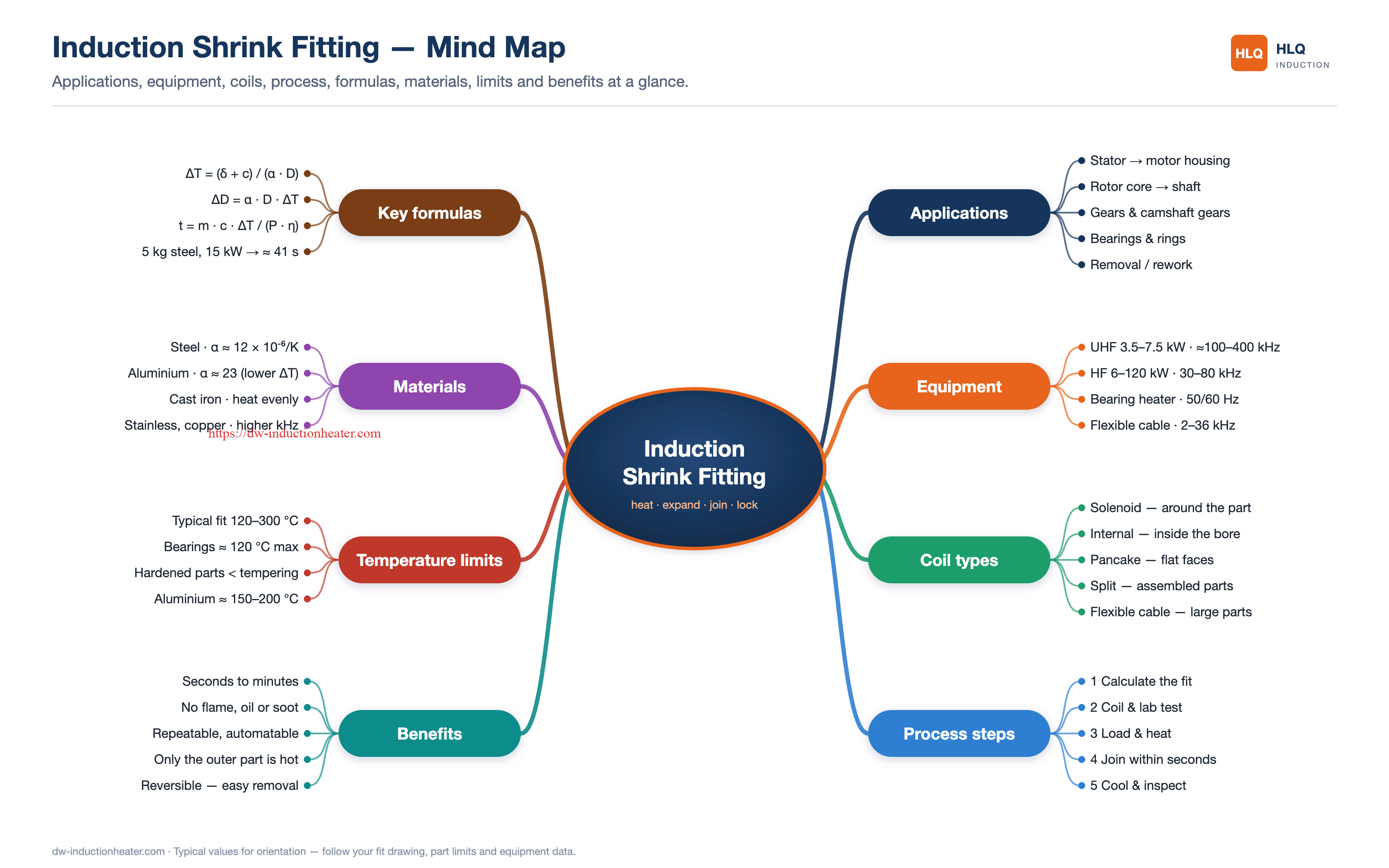
Advantages and Limitations of Induction Shrink Fitting
Advantages
- Localized Heating: Heat can be concentrated in the component or region requiring expansion.
- Non-Contact Heating: Electromagnetic induction eliminates the need for direct contact with a heating element.
- No Open Flame: Induction heating avoids the direct flame associated with gas torches.
- Repeatable Process Control: Adjustable power and heating time support standardized production procedures.
- Reduced Mechanical Assembly Force: Adequate thermal clearance can reduce insertion force and surface damage.
- Automation Compatibility: Induction heating stations can be integrated with fixtures, handling equipment, and monitoring systems.
- Application Flexibility: Different coils and power supplies can be matched to different mechanical components.
Limitations
- Temperature Restrictions: Hardened, tempered, sealed, or temperature-sensitive components may have strict heating limits.
- Coil Design Requirements: Incorrect coil geometry can lead to poor coupling and uneven temperature distribution.
- Thermal Gradients: Rapid surface heating may create temperature differences through thick sections.
- Initial Equipment Cost: An induction heating system generally requires higher initial investment than simple manual heating tools.
- Cooling Requirements: Many industrial induction generators and coils require an appropriately designed cooling system.
- Assembly Timing: Installation must be completed before thermal contraction eliminates the required clearance.
Comparison of Industrial Heating Methods
| Heating Method | Typical Strength | Main Limitation |
|---|---|---|
| Induction Heating | Fast, controllable localized heating | Requires matched coil and power supply |
| Electric Oven | Uniform heating of multiple accessible components | Longer warm-up time and larger heated mass |
| Gas Torch | Simple portable heating | Less predictable heating distribution and open-flame risks |
| Oil Bath | Relatively uniform heat transfer | Fluid handling, cleaning, and temperature limitations |
| Resistance Heater | Suitable for selected component geometries | Requires appropriate contact or thermal coupling |
Why Choose HLQ Induction Shrink Fitting Equipment?
HLQ Induction Equipment Co., Ltd. supplies industrial induction heating equipment for applications including brazing, forging, hardening, annealing, shrink fitting, preheating, and metal processing.
1. Multiple Induction Heating Platforms
HLQ publishes medium-frequency, high-frequency, and ultra-high-frequency induction heating equipment suitable for different component geometries and heating requirements.
2. Application-Oriented Equipment Selection
Power and frequency can be evaluated according to workpiece mass, thermal expansion requirements, component geometry, and production cycle.
3. Custom Induction Coil Configuration
Coil dimensions and winding geometry can be adapted to the target heating zone and mechanical assembly arrangement.
4. Industrial Application Experience
HLQ provides published examples involving gear shrink fitting, induction heating of shafts, coupling applications, and mechanical thermal assembly.
5. Integration Possibilities
Depending on the project configuration, induction heating may be integrated with temperature monitoring, component positioning, production fixtures, and automated handling equipment.
Engineering-Focused System Configuration
The most appropriate induction shrink fitting machine is not necessarily the model with the highest rated power.
A properly engineered system should balance heating speed, temperature uniformity, process safety, component quality, equipment efficiency, and production repeatability.
Final specifications and achievable performance should be established through verified engineering calculations and application testing.
10 Core FAQs About Induction Shrink Fitting Machines
1. What is induction shrink fitting?
Induction shrink fitting is a thermal assembly process in which an induction heater expands a conductive outer component temporarily. A shaft or mating component is inserted while sufficient clearance exists. As the outer component cools, it contracts and creates an interference fit.
2. What components can be assembled using induction shrink fitting?
Common applications include gears, shaft sleeves, couplings, hubs, rings, selected bearings, flanges, and electric motor components. Suitability depends on component geometry, material properties, and permissible heating temperature.
3. What temperature is required for induction shrink fitting?
The required temperature depends on the initial bore diameter, diametral interference, desired assembly clearance, thermal expansion coefficient, and initial temperature. There is no universal temperature that is suitable for every material or component.
4. How do I calculate the temperature needed for shrink fitting?
For approximately uniform, unconstrained expansion, the theoretical temperature rise can be estimated using ΔT = (δ + C) / (α × D), where δ is the diametral interference, C is the required assembly clearance, α is the thermal expansion coefficient, and D is the initial bore diameter.
5. How much power does an induction shrink fitting machine need?
Required power depends on component mass, specific heat capacity, target temperature rise, heating time, and effective energy transfer. A preliminary estimate can be made using P = m × cp × ΔT / (η × t). Final power selection requires verification of generator output and coil performance.
6. Is medium-frequency or high-frequency induction heating better for shrink fitting?
High-frequency induction heating is often suitable for relatively small or localized heating zones. Medium-frequency systems may be preferable for larger or thicker components requiring greater heating penetration. The final selection depends on material properties, component geometry, and heating uniformity.
7. Can induction heating damage hardened gears or bearings?
Yes, if the component is overheated or exposed to excessive thermal gradients. Hardened gears, bearing assemblies, and heat-treated materials may have strict maximum temperature limits. These limits must be verified before heating.
8. Can induction heating be used to remove tightly fitted couplings or bearings?
Yes. Controlled induction heating can create differential thermal expansion and assist the removal of selected interference-fit components. The process must account for heat transfer to the inner component, available extraction force, and mechanical access.
9. How can induction shrink fitting quality be controlled?
Quality can be controlled by measuring the initial interference, monitoring component temperature, maintaining consistent coil positioning, controlling assembly time, and inspecting final alignment, runout, and dimensional accuracy.
10. Can induction shrink fitting be integrated into an automatic production line?
Yes. Depending on the application, induction heating equipment can be combined with automated positioning, handling fixtures, temperature monitoring, process interlocks, and production data recording. The specific automation arrangement must be engineered for the target components and cycle time.