Induction Shrink Fitting Shaft Gears
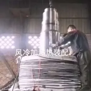
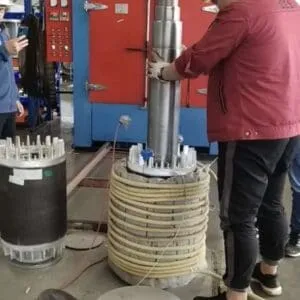
Induction shrink fitting of shaft gears means heating only the gear with an induction coil until its bore expands past the shaft diameter. The shaft is then dropped in, and the gear grips it as it cools, forming an interference fit with no press force.
- Fit temperature: ΔT = (interference + clearance) / (α · D). This is typically 200–270 °C for steel gears, 120–160 °C for aluminium, and at most about 150 °C for case-hardened gears.
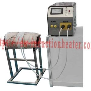
- Equipment: HLQ UHF heaters (3.5–7.5 kW) for small gears, HF heaters (6–120 kW) for production lines, and flexible-cable heaters for large gears.
- Cycle: About 1–5 minutes for small gears. For example, a Ø152 mm camshaft gear is heated in 3 minutes with 3.5 kW.
What is Induction Shrink Fitting of Shaft Gears?
A gear is fixed to its shaft by an interference fit: the gear bore is made slightly smaller than the shaft. Pressing the parts together cold needs high force and can score both surfaces. Heating the gear instead expands the bore so that the shaft slides in freely. When the gear cools, it contracts and grips the shaft with a uniform contact pressure that transmits torque without keys or adhesives.
Induction is the fastest and cleanest way to heat the gear. A copper coil carrying high-frequency current induces eddy currents in the gear, so heat is generated inside the part in minutes, with no flame, oil bath or oven. The same method is used for bearings, couplings and flanges; see our induction shrink fitting machine overview.
| Method | Heating time | Temperature control | Drawbacks |
|---|---|---|---|
| Induction coil | Seconds to minutes | Timer, pyrometer or thermocouple; repeatable | Coil must suit the gear size |
| Oven | 30–120 min | Good but slow | Long cycle, high energy, large footprint |
| Oil bath | 10–30 min | Limited by the oil flash point (≈ 200 °C) | Smoke, cleaning, fire risk |
| Gas torch | Minutes | Poor; local overheating | Distortion, softening of hardened teeth |
| Hydraulic press (cold) | Seconds | — | Scoring, fretting, high force, damage risk |
Key Applications
| Industry | Assembly | Typical heater |
|---|---|---|
| Automotive and engines | Camshaft gears, crankshaft gears, timing gears | UHF 3.5–7.5 kW, pancake or helical coil |
| Gearboxes and reducers | Gears and pinions on output and intermediate shafts | HF 15–60 kW, encircling coil |
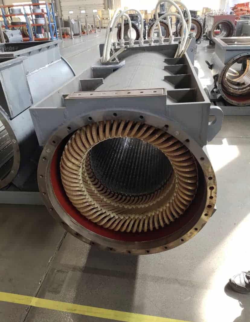
| Electric motors | Rotor cores, fans and gears on shafts | HF 15–60 kW |
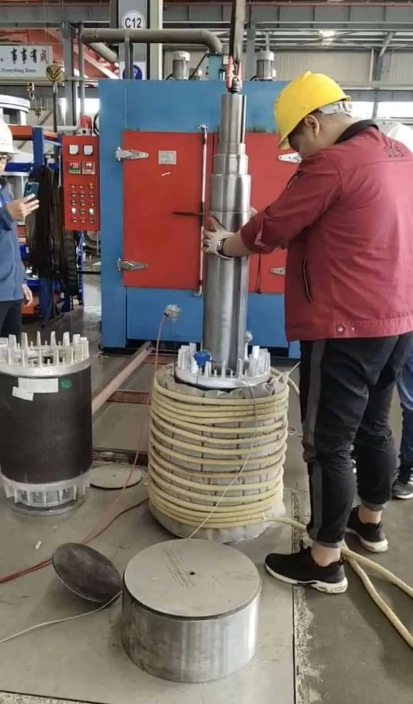
| Mining, cement, steel mills | Large gears, girth gears and couplings, assembly and removal | Flexible-cable heaters |
| Marine and heavy machinery | Couplings, hubs and gears in maintenance | Portable flexible-cable heaters |
Application cases


For removal work, see induction thermal disassembly of gears and couplings.
Suitable Materials
| Gear material | α (×10⁻⁶ /K) | c (kJ/kg·K) | Typical fit temperature | Notes |
|---|---|---|---|---|
| Carbon / alloy steel (soft or through-hardened) | ≈ 12 | ≈ 0.49 | 200–270 °C | Magnetic, so it heats efficiently; avoid going above 300 °C |
| Case-hardened or induction-hardened steel | ≈ 12 | ≈ 0.49 | 120–150 °C | Stay below the tempering temperature (often 150–180 °C) |
| Cast iron | ≈ 10–11 | ≈ 0.46 | 150–250 °C | Heat evenly to avoid cracking |
| Aluminium alloys | ≈ 23 | ≈ 0.90 | 120–160 °C | Large expansion, low fit temperature; higher frequency |
| Bronze | ≈ 18 | ≈ 0.38 | 150–200 °C | Non-magnetic, needs high frequency |
| Austenitic stainless steel | ≈ 16–17 | ≈ 0.50 | 150–250 °C | Non-magnetic, lower efficiency |
Always confirm the maximum allowed temperature with the gear maker, especially for hardened, nitrided or coated gears.
Working Principle

- Induction heating: The power supply drives high-frequency current through a coil placed under or around the gear. Eddy currents heat the gear from within.
- Bore expansion: The bore grows by ΔD = α · D · ΔT. Heating continues until the bore is larger than the shaft plus a small assembly clearance.
- Assembly: The shaft is inserted, often dropping in under its own weight, against a stop that sets the axial position.
- Cooling: The gear contracts onto the shaft. In the camshaft gear case below, the shaft was gripped within 30 seconds.
Background: how induction heating works.
Required temperature rise by interference
| Diametral interference | + clearance | Steel gear ΔT | Steel fit temp. (from 20 °C) | Aluminium ΔT | Aluminium fit temp. |
|---|---|---|---|---|---|
| 0.5 ‰ of D | 0.5 ‰ | 83 K | ≈ 105 °C | 43 K | ≈ 65 °C |
| 1.0 ‰ of D | 0.5 ‰ | 125 K | ≈ 145 °C | 65 K | ≈ 85 °C |
| 1.5 ‰ of D | 0.5 ‰ | 167 K | ≈ 190 °C | 87 K | ≈ 110 °C |
| 2.0 ‰ of D | 0.5 ‰ | 208 K | ≈ 230 °C | 109 K | ≈ 130 °C |
ΔT = (interference + clearance) / α, with interference and clearance expressed as a fraction of D. Add 20–30 K margin for the heat lost while moving the gear to the shaft.
Bore growth at a given temperature rise
| Bore D | Steel, ΔT 150 K | Steel, ΔT 200 K | Aluminium, ΔT 120 K |
|---|---|---|---|
| 25 mm | 0.045 mm | 0.060 mm | 0.069 mm |
| 50 mm | 0.090 mm | 0.120 mm | 0.138 mm |
| 75 mm | 0.135 mm | 0.180 mm | 0.207 mm |
| 100 mm | 0.180 mm | 0.240 mm | 0.276 mm |
| 150 mm | 0.270 mm | 0.360 mm | 0.414 mm |
Coil options for gears
| Coil type | How it is used | Best for |
|---|---|---|
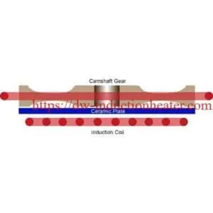
| Pancake (face) coil | The gear lies flat on a ceramic plate above the coil | Small flat gears, simple loading |
| Encircling (solenoid) coil | The coil surrounds the gear OD | Most uniform heating of gears and hubs |
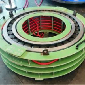
| Flexible cable coil | Cable wound on the gear rim or hub | Large gears, girth gears, on-site work |
Technical Specifications
| Heater family | Power | Frequency | Coil | Cooling | Best for |
|---|---|---|---|---|---|
| HLQ UHF heaters (DW-UHF) | 3.5–7.5 kW | ≈ 100–400 kHz | Pancake or helical, custom | Water (closed-loop chiller) | Small gears up to ≈ Ø150 mm |
| HLQ HF heaters (DW-HF) | 6–120 kW | 30–80 kHz | Encircling, pancake, internal | Water (closed-loop chiller) | Gears and hubs Ø50–400 mm, production lines |
| MF flexible-cable heaters | 10–160 kW | 2–36 kHz | Water- or air-cooled cable | Per model | Large gears, rings and couplings, on site |
Shrink fitting station parameters
| Item | Typical setting |
|---|---|
| Temperature control | Timer, IR pyrometer or K-type thermocouple with set-point cut-off |
| Heating time | 1–5 min for small gears; seconds to minutes with HF power |
| Remote heat station | Capacitor bank matched to the coil (e.g. 0.66 μF in the camshaft gear case) |
| Fixture | Ceramic plate or locating nest, plus a vertical shaft holder with an axial stop |
| Operation | Foot switch for manual stations; PLC I/O for automated lines |
Heating time by gear mass and heater power (steel, ΔT 200 K, η 0.6)
| Steel gear mass | 3.5 kW | 6 kW | 15 kW | 30 kW |
|---|---|---|---|---|
| 1 kg | 47 s | 27 s | 11 s | 5 s |
| 3 kg | 140 s | 82 s | 33 s | 16 s |
| 7 kg | 327 s | 191 s | 76 s | 38 s |
| 15 kg | 700 s | 408 s | 163 s | 82 s |
t = m · c · ΔT / (P · η). Very short times heat only the surface, so allow a soak time for the bore to reach temperature.
Recommended Model Selection
| Gear | Recommended heater | Coil |
|---|---|---|
| Steel gear ≤ 3 kg, cycle 1–4 min | UHF 3.5–7.5 kW | Pancake or helical |
| Steel gear 3–15 kg in production | HF 15–30 kW | Encircling |
| Gear 15–100 kg or a short takt time | HF 30–120 kW | Encircling, custom |
| Large gears, rings and couplings, on site | MF flexible-cable heater | Flexible cable |
| Rolling bearings on shafts | Induction bearing heater | Yoke or coil |
Bearings follow different temperature rules (≈ 120 °C maximum). See our induction bearing heater page.
Process Workflow

| Step | Action | Check |
|---|---|---|
| 1 | Calculate ΔT from the interference, the clearance and the gear’s maximum temperature | Fit temperature below the gear limit |
| 2 | Clean the bore and shaft; set the shaft in the fixture against its stop | No burrs, oil or dirt |
| 3 | Place the gear on or in the coil | Centred, with no steel tooling near the coil |
| 4 | Heat to the set point (timer, pyrometer or thermocouple) | Uniform temperature at the bore |
| 5 | Move the gear to the shaft within seconds and insert | Seats fully against the stop |
| 6 | Hold in position until the gear grips, then cool in air | No axial movement |
| 7 | Inspect | Position, run-out, and torque test if required |
Typical station layout

Common Problems and Solutions
| Problem | Likely cause | Solution |
|---|---|---|
| Shaft sticks halfway | Gear cooled during transfer, or ΔT too low | Add 20–30 K margin, shorten the transfer, preposition the shaft |
| Teeth hot, bore still cold | Heating too fast or frequency too high for the section | Lower the power, add a soak time, or use a lower frequency |
| Hardness drop on the teeth | Fit temperature above the tempering temperature | Limit with a pyrometer cut-off; use a lower ΔT and tighter clearance control |
| Uneven expansion, gear tilts | Gear off-centre in the coil | Use a locating nest; use an encircling coil for better uniformity |
| Fixture or tooling gets hot | Steel parts inside the coil field | Use non-magnetic or ceramic fixtures near the coil |
| Heater alarm or low power | Coil–capacitor mismatch or cooling fault | Check the tuning, water flow and chiller temperature |
Engineering Selection Guide
| Factor | Question to answer | Guideline |
|---|---|---|
| Fit temperature | What interference, and what is the gear’s maximum temperature? | Use the ΔT table; hardened gears ≤ 150 °C |
| Gear mass | How many kg must be heated? | Use the heating-time table to size the power |
| Geometry | Solid disc, webbed gear or large ring? | Encircling coil for hubs; cable coil for large rings |
| Cycle time | Parts per hour? | Production lines use HF power with automation I/O |
| Location | Workshop or on site? | On site: portable induction shrink fitting machine |
| Other parts | Flanges or rings as well? | See induction shrink fitting of steel flanges |
Advantages and Limitations
| Advantages | Limitations |
|---|---|
| Heats only the gear, in minutes | A coil must be designed for each gear size range |
| No flame, oil smoke or press force | UHF and HF heaters need water cooling |
| Repeatable, set-point-controlled temperature | Hardened gears limit the usable ΔT |
| No scoring or fretting of the shaft | Fast transfer is needed before the gear cools |
| The same heater can remove gears | Higher upfront cost than a gas torch |
Why Choose HLQ?
| Strength | What it means for you |
|---|---|
| Full power range | 3.5 kW UHF to 120 kW HF, plus flexible-cable heaters |
| Application testing | Coil and cycle proven on your gear before delivery |
| Custom coils | Pancake, encircling, split and cable designs |
| Temperature control | Timer, pyrometer or thermocouple cut-off |
| Assembly and removal | One heater for mounting and dismounting |
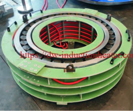

Application example: camshaft gears
| Item | Steel gear | Aluminium gear |
|---|---|---|
| Gear size | Ø152 × 51 mm (6 × 2 in), webbed | Ø152 × 51 mm (6 × 2 in) |
| Target temperature | ≈ 270 °C (518 °F) | ≈ 160 °C (320 °F) |
| Power supply | DW-UHF-3.5 kW | DW-UHF-3.5 kW |
| Frequency | 151 kHz | 158 kHz |
| Heating time | 3 min | 4 min |
| Grip after insertion | 30 s | 30 s |
| Total cycle | 3.5 min | 4.5 min |
Setup: pancake coil under a ceramic plate, remote heat station with one 0.66 μF capacitor, K-type thermocouple check. The shafts dropped into the gears after heating and were gripped tightly within 30 seconds.
10 Core FAQs
1. What is induction shrink fitting of shaft gears?
It is heating a gear by induction so that its bore expands, inserting the shaft, and letting the gear cool to form an interference fit.
2. How hot must the gear be?
Hot enough for the bore to clear the shaft: ΔT = (interference + clearance) / (α · D). Steel gears are usually 200–270 °C; aluminium gears 120–160 °C.
3. Will heating soften a hardened gear?
Not if the gear stays below its tempering temperature. Case-hardened gears are usually limited to about 150 °C, controlled by a pyrometer or thermocouple cut-off.
4. How long does it take?
About 1–5 minutes for small gears at 3.5–7.5 kW. For example, a Ø152 mm steel camshaft gear takes 3 minutes at 3.5 kW. Larger gears use 15–120 kW HF heaters.
5. Which coil is best for gears?
Encircling coils heat most uniformly. Pancake coils are simple for small flat gears, and flexible cable coils suit large gears and site work.
6. What frequency is used?
About 150–160 kHz worked well for Ø152 mm gears. In general, use 100–400 kHz (UHF) for small gears, 30–80 kHz (HF) for medium gears, and 2–36 kHz for large gears.
7. Can the same heater remove gears?
Yes. Heat the gear rim and hub quickly so they expand before the heat reaches the shaft, then pull the gear off.
8. Is induction better than an oven or oil bath?
Induction takes minutes instead of 10–120 minutes, avoids oil smoke and fire risk, and heats only the gear.
9. Do I need water cooling?
Yes, UHF and HF heaters and fixed coils use a closed-loop water chiller. Some flexible-cable systems are air-cooled.
10. Can aluminium gears be shrink fitted?
Yes. Aluminium expands about twice as much as steel, so a lower fit temperature (≈ 120–160 °C) is enough. In the camshaft case, an aluminium gear reached 160 °C in 4 minutes at 3.5 kW.