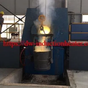
Iron Steel Melting Induction Furnace
Iron and Steel Melting Induction Furnace
Quick Answer
An iron and steel melting induction furnace uses an alternating magnetic field to generate heat in a conductive metal charge. HLQ’s published GW model table covers nominal capacities of 0.35–30 t, rated powers of 250–15000 kW and frequencies of 0.25–1 kHz. Selection depends on the metal grade, charge condition, required melt quantity, electrical infrastructure, cooling and tapping schedule.
The source table provides material-specific energy figures for cast iron, copper, brass and aluminum. It does not publish a separate steel energy-consumption column.
Table of Contents
- Quick Answer
- What is the Iron and Steel Melting Induction Furnace?
- Key Applications
- Suitable Materials
- Working Principle
- Technical Specifications
- Recommended Model Selection
- Process Workflow
- Common Problems and Solutions
- Engineering Selection Guide
- Advantages and Limitations
- Why Choose HLQ?
- 6 Core FAQs
What is the Iron and Steel Melting Induction Furnace?
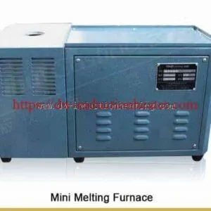
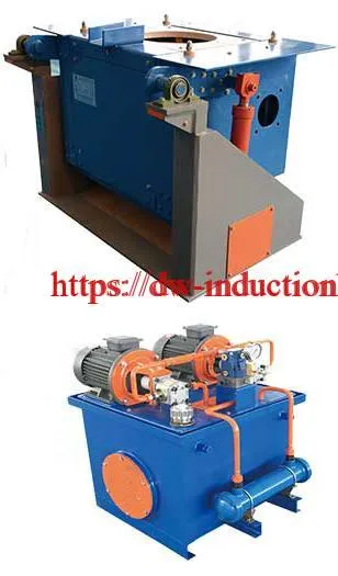
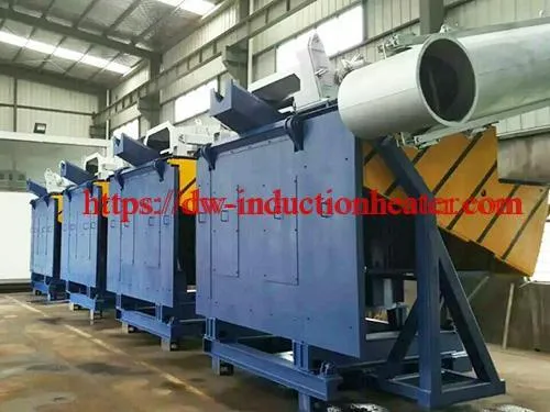
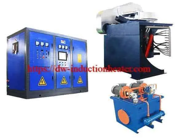
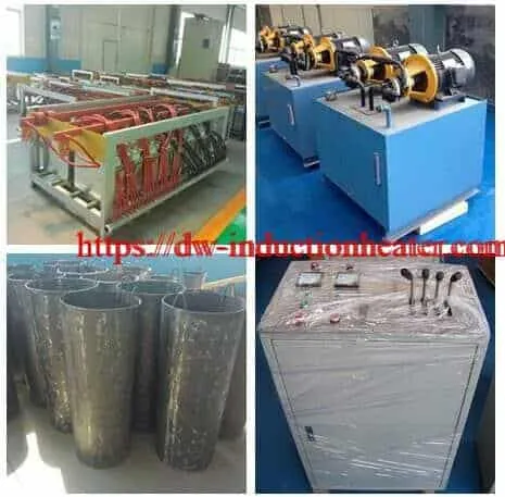
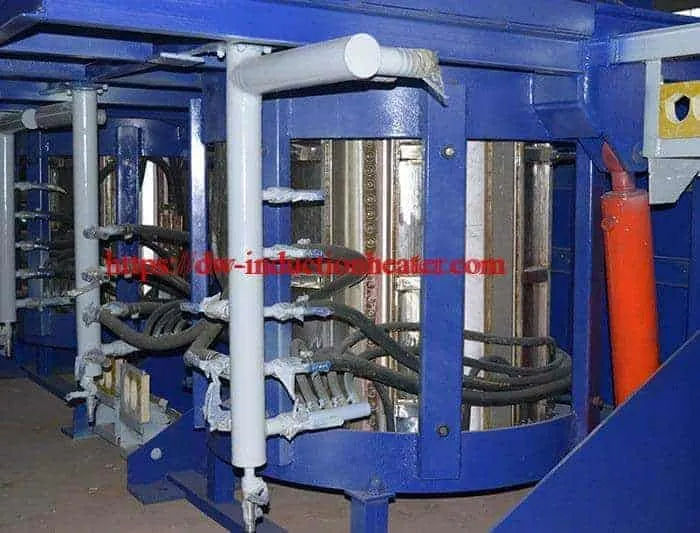
This medium-frequency electric furnace system is intended for melting suitable iron, steel and alloy charges before casting. The published configuration includes an induction power supply, capacitor cabinet, furnace body, tilting system and water-cooled cables.
The description emphasizes a steel-shell furnace with hydraulic tilting. Its configuration note also mentions aluminum-shell bodies and reducer-based tilting, so the delivered mechanical arrangement must be confirmed for the selected model.
Related categories retained from the original page include steel and iron melting furnaces, induction melting furnaces, tilting induction melting furnaces, metal melting furnaces and electric furnaces.
Key Applications
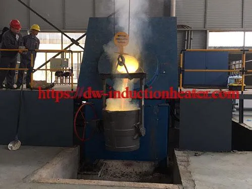
- Cast-iron charge melting for foundry mould filling.
- Steel charge melting followed by temperature and chemistry checks.
- Stainless-steel remelting using a grade-specific charge and lining procedure.
- Coordinating repeated melting heats with ladle transfer and casting demand.
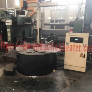
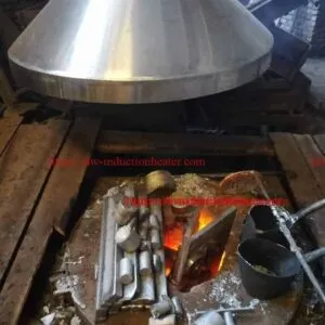
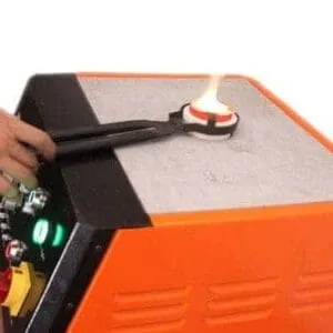
The application illustration represents process scenarios, not documented customer projects or guaranteed casting results.
Suitable Materials
| Material | Published scope | Engineering check |
|---|---|---|
| Cast iron | Named application with a dedicated energy column | Charge composition, lining, melt treatment and casting schedule |
| Steel | Named application; no dedicated steel energy column | Grade, charge cleanliness, required temperature and chemistry control |
| Stainless steel | Included in the product description | Alloy compatibility, contamination control and refractory selection |
| Copper, brass and aluminum | Listed in the general energy table | Separate furnace-volume, lining and operating assessment |
The source bases nominal capacity on steel density. A listed steel capacity must not be transferred directly to another metal as an equal-mass working capacity. Changing metal also requires more than a density calculation.
Working Principle
- The electrical supply is converted through a rectifier and DC link.
- An inverter produces medium-frequency power for the matched coil and capacitor circuit.
- Alternating coil current creates a changing magnetic field.
- Induced currents in the metal generate resistive heat, raising its temperature and producing a melt.
- The melt is checked and transferred through the configured tapping arrangement.
The refractory contains and insulates the bath. This explanation concerns induction heating of the metal, without arc electrodes or a resistance heating element. Exact power-converter and capacitor topology must follow the equipment drawing.
See the explanation of induction heating principles and the related medium-frequency induction power supply. Related generator models have their own specifications and should not be substituted for GW furnace ratings.
Technical Specifications
The following tables reorganize the original GW data while retaining all 12 model rows. Values are published references; the operating and measurement conditions require confirmation for the intended charge.
Model, Capacity, Power, Frequency and Melting Time
| Model | Nominal capacity (t) | Rated power (kW) | Frequency (kHz) | Melting time (min) |
|---|---|---|---|---|
| GW-0.35T | 0.35 | 250 | 1 | 20–45 |
| GW-0.5T | 0.5 | 350 | 0.8 | 30–50 |
| GW-0.75T | 0.75 | 500 | 0.8 | 40–50 |
| GW-1T | 1 | 800 | 0.7 | 40–50 |
| GW-1.5T | 1.5 | 1000 | 0.7 | 40–60 |
| GW-2T | 2 | 1400 | 0.5 | 45–60 |
| GW-3T | 3 | 2000 | 0.5 | 50–70 |
| GW-5T | 5 | 3000 | 0.3 | 50–80 |
| GW-10T | 10 | 6000 | 0.3 | 50–90 |
| GW-15T | 15 | 8000 | 0.3 | 50–90 |
| GW-20T | 20 | 10000 | 0.25 | 50–90 |
| GW-30T | 30 | 15000 | 0.25 | 50–90 |
The introductory prose states 0.15–20 t, whereas the actual table spans 0.35–30 t. This page uses the tabulated range. The general claim of melting in less than 40 minutes does not describe every listed model or charge.
Electrical Reference Data
Input supply frequency is listed as 50/60 Hz. Slash-separated entries below preserve the first and second source entries; they are not ranges or independently interchangeable selections.
| Model | Incoming voltage (V) | Incoming line current (A) | Rectifier pulses | Transformer source entry (kVA) | DC voltage (V) | DC current (A) | Medium-frequency voltage (V) |
|---|---|---|---|---|---|---|---|
| GW-0.35T | 380 | 400 | 6 | Three-phase; 315 | 500 | 500 | 750 |
| GW-0.5T | 380 | 560 | 6 | Three-phase; 400 | 500 | 700 | 750 |
| GW-0.75T | 380 | 800 | 6 | Three-phase; 630 | 500 | 1000 | 750 |
| GW-1T | 380 / 750 | 1280 / 656 | 6 / 6 | Three-phase; 1000 / Three-phase; 1000 | 500 / 990 | 1600 / 808 | 750 / 1480 |
| GW-1.5T | 380 / 750 | 800 / 820 | 12 / 6 | Double three-phase; 1250 / Three-phase; 1250 | 500 / 990 | 1000 / 1010 | 750 / 1480 |
| GW-2T | 750 / 750 | 1148 / 574 | 6 / 12 | Three-phase; 1800 / Double three-phase; 1800 | 990 / 990 | 1414 / 707 | 1480 / 1480 |
| GW-3T | 750 | 820 | 12 | Double three-phase; 2500 | 990 | 1010 | 1480 |
| GW-5T | 950 | 1140 | 12 | Double three-phase; 4000 | 1260 | 1190 | 1900 |
| GW-10T | 950 | 2280 | 12 | Double three-phase; 8000 | 1260 | 2380 | 1900 |
| GW-15T | 950 | 1520 | 24 | Four three-phase; 10000 | 1260 | 1590 | 1900 |
| GW-20T | 950 | 1900 | 24 | Four three-phase; 12500 | 1260 | 1980 | 1900 |
| GW-30T | 950 | 2850 | 24 | Four three-phase; 20000 | 1260 | 2980 | 1900 |
GW-1T, GW-1.5T and GW-2T each contain paired electrical entries. Confirm the matched configuration before selection. The original descriptions of three-phase, double three-phase and four three-phase transformers are retained; they do not establish how to total winding or branch currents.
Use the approved electrical schedule to establish site current, transformer arrangement, protection and cable sizing. Do not multiply or add the source current values without that schedule.
Published Material-Specific Energy Figures
| Model | Cast iron | Red copper | Brass | Aluminum |
|---|---|---|---|---|
| GW-0.35T | 560 | 420 | 390 | 540 |
| GW-0.5T | 550 | 410 | 380 | 530 |
| GW-0.75T | 550 | 410 | 380 | 530 |
| GW-1T | 540 | 400 | 370 | 520 |
| GW-1.5T | 530 | 390 | 360 | 510 |
| GW-2T | 520 | 380 | 350 | 500 |
| GW-3T | 510 | 370 | 340 | 490 |
| GW-5T | 500 | 360 | 330 | 480 |
| GW-10T | 490 | 350 | 320 | 470 |
| GW-15T | 480 | 340 | 310 | 460 |
| GW-20T | 470 | 330 | 300 | 450 |
| GW-30T | 470 | 330 | 300 | 450 |
Steel energy consumption is not separately published. The cast-iron column must not be relabelled as steel performance. The source does not fully define the energy-metering boundary, charge condition, working mass or treatment and holding allowances.
Published In-Furnace Temperature References
| Material | Source temperature (°C) |
|---|---|
| Steel | 1650 |
| Cast iron | 1450 |
| Red copper | 1150 |
| Brass | 1000 |
| Aluminum | 700 |
| Zinc | 400 |
These entries reproduce the source’s in-furnace temperature references. They are not universal melting points, maximum furnace ratings or pouring setpoints for every alloy.
Zinc entry requires verification: The original 400°C entry is retained for traceability only and must not be used as a validated zinc-melting temperature.
Additional Calculated Comparison Data
The next table contains arithmetic derived from the published model data. Frequency in Hz equals kHz multiplied by 1000. Rated power per nominal tonne equals listed kW divided by listed capacity in t, rounded to one decimal place. Neither calculation is a measured efficiency or production-rate result.
| Model | Frequency (Hz) | Rated power / nominal capacity (kW/t) |
|---|---|---|
| GW-0.35T | 1000 | 714.3 |
| GW-0.5T | 800 | 700.0 |
| GW-0.75T | 800 | 666.7 |
| GW-1T | 700 | 800.0 |
| GW-1.5T | 700 | 666.7 |
| GW-2T | 500 | 700.0 |
| GW-3T | 500 | 666.7 |
| GW-5T | 300 | 600.0 |
| GW-10T | 300 | 600.0 |
| GW-15T | 300 | 533.3 |
| GW-20T | 250 | 500.0 |
| GW-30T | 250 | 500.0 |
Construction and Control Features Listed in the Source
- Digital control, constant-power control and sweep-frequency starting are described.
- Overcurrent, overvoltage, limiting and water-failure protection functions are listed.
- The coil description specifies TU1 copper, brazed joints and turn insulation.
- The component description mentions carbon-free hoses, 304 stainless-steel clamps, optical-fibre triggering, capacitors, copper busbars and an isolation/changeover switch.
- The cooling description includes a plate heat exchanger; the extraction description includes a furnace cover and dust-collection interface.
Confirm these details against the selected configuration. The published power-factor claim of at least 0.96 is not a thermal-efficiency rating. No verified harmonic spectrum, universal savings percentage or site-emissions result is established here.
Recommended Model Selection
| Nominal group | Models | Selection priority |
|---|---|---|
| 0.35–0.75 t | GW-0.35T, GW-0.5T, GW-0.75T | Charge geometry, useful working mass and batch rhythm |
| 1–2 t | GW-1T, GW-1.5T, GW-2T | Resolve the paired electrical configurations and match tapping demand |
| 3–5 t | GW-3T, GW-5T | Transformer arrangement, cooling and ladle handling |
| 10–30 t | GW-10T, GW-15T, GW-20T, GW-30T | Site power infrastructure, complete heat cycle and casting-line coordination |
This shortlist is an engineering starting point, not a guarantee of usable output. Confirm the actual charge, lining, working capacity, melt endpoint and complete cycle before final selection.
For related pouring arrangements, see the hydraulic tilting induction furnace. Its configuration is a separate equipment reference.
Process Workflow
- Verify charge and grade: establish material identity, composition compatibility and traceability.
- Check furnace readiness: follow the approved lining, cooling, electrical, extraction and tilting checks.
- Charge under the approved procedure: use suitable charge preparation, dimensions and loading limits.
- Melt and monitor: control the heat according to the equipment and alloy procedure.
- Check temperature and chemistry: release the melt only against the specified acceptance requirements.
- Tap to ladle and cast: coordinate transfer, treatment where required, and mould readiness.
Melting time is only one part of the heat cycle. Charging, sampling, treatment, holding, tapping and turnaround also affect useful production.
Common Problems and Solutions
These are investigation paths, not confirmed fault diagnoses. Follow the equipment procedure and use qualified personnel for electrical, cooling and refractory work.
| Observation | Possible contributor | Check |
|---|---|---|
| Longer heat cycle | Power/load mismatch, charge arrangement or extended non-melting stages | Compare actual power and each cycle stage with a defined charge |
| High measured kWh/t | Holding losses, lining condition, reduced useful output or an inconsistent measurement boundary | Record energy and usable tapped mass for the same production period |
| Unexpected chemistry | Charge mixing or unverified additions | Review material traceability and the sampling/treatment procedure |
| Lining deterioration | Refractory mismatch, thermal cycling or charging damage | Follow the approved inspection, repair and preparation requirements |
| Cooling or electrical alarm | A monitored protection condition | Resolve the cause under the fault procedure; do not bypass interlocks |
| Temperature inconsistency | Measurement or control issue | Verify sensor condition, calibration and the approved measurement method |
Engineering Selection Guide
| Area | Required information | Purpose |
|---|---|---|
| Metal and charge | Grade, charge source, dimensions, condition and required useful melt mass | Establish capacity and refractory requirements |
| Thermal process | Initial condition, target temperature, treatment and holding requirements | Define the complete heat duty |
| Electrical system | Verified voltage, transformer arrangement, current basis and power-quality requirements | Match the supply and protection design |
| Coil and lining | Approved geometry, refractory specification and maintenance procedure | Match the electromagnetic and containment systems |
| Cooling and extraction | Equipment-specific water requirements and site extraction design | Define supporting utilities without assuming unlisted flow rates |
| Handling and casting | Charging method, tilting arrangement, ladle route and mould schedule | Integrate the furnace with the foundry |
| Acceptance testing | Defined charge, endpoint, measurement boundaries and useful output | Compare actual performance on a consistent basis |
Coil geometry and condition affect equipment matching. The related induction heating coils category provides further component context.
For a measured production comparison, calculate specific electrical energy as metered kWh divided by useful tapped tonnes, and average output as useful tapped tonnes divided by elapsed hours. Define auxiliary loads and account for changes in retained metal inventory.
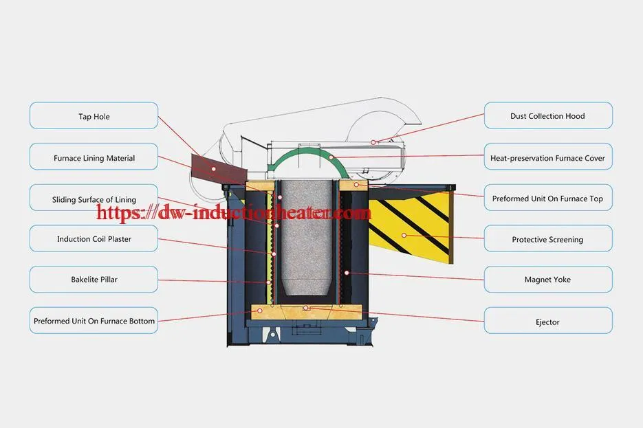
The conceptual layout illustrates process interfaces only. No footprint, foundation load, cooling flow, extraction rate or safety clearance is supplied by the original specification.
Advantages and Limitations
Relevant Advantages
- Induction produces heat within the conductive metal charge.
- The GW table provides several nominal capacity, power and frequency combinations.
- The listed control and protection functions support managed furnace operation.
- Configured tilting equipment can connect melting with ladle transfer.
Selection Limits
- Metal grade and charge control remain necessary for the required chemistry.
- The cast-iron energy figures do not establish steel energy consumption.
- Published melting time is not the complete foundry production cycle.
- Cooling, refractory condition and electrical maintenance are essential.
- Power factor does not equal thermal efficiency or zero harmonic distortion.
- Dust extraction performance and site compliance require a defined system and verification.
For a wider technology comparison, see induction melting vs resistance and gas melting.
Why Choose HLQ?
HLQ publishes induction-furnace equipment information and describes an engineering approach that considers material, temperature, heating time, power supply, coil, cooling and control requirements together.
For iron and steel melting, these factors should be evaluated alongside the lining, charge preparation, ladle route and casting schedule. The HLQ induction furnace engineering information describes the company’s selection and customization capabilities.
Final assessment should use the selected configuration, approved drawings and agreed acceptance conditions.
6 Core FAQs
1. What capacity range is actually listed?
The GW table lists 0.35–30 t, from GW-0.35T to GW-30T. The introductory claim of 0.15–20 t is inconsistent with that table and does not document an additional 0.15 t model.
2. Is about 530 kWh/t a steel energy rating?
No. The prose associates that figure with cast iron, and the model table has no separate steel column. The listed cast-iron figures vary by model.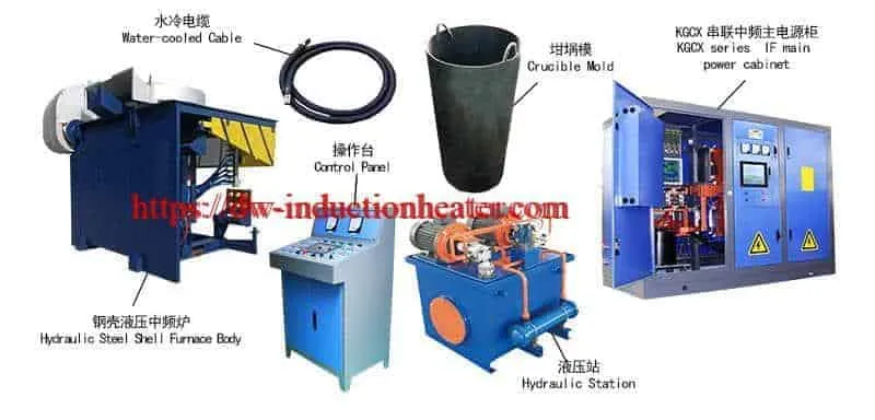
3. Will every model melt a heat in less than 40 minutes?
No. The table lists model-dependent ranges extending to 90 minutes. Actual conditions and complete-cycle stages must be defined before comparing production output.
4. How should the paired electrical values be interpreted?
GW-1T, GW-1.5T and GW-2T contain first and second source entries. Confirm the matched configuration and whether current references apply to a branch or complete assembly before electrical design.
5. Are 1650°C for steel and 1450°C for cast iron universal setpoints?
No. They are the source’s in-furnace reference entries. Actual operating and pouring requirements depend on the grade, treatment and casting procedure.
6. Is this an electric arc furnace or an ore-smelting system?
The page describes induction melting of metal charges. Its legacy EAF table label does not establish an arc-heating design or an ore-reduction process. Charge control and melt checks remain necessary.