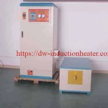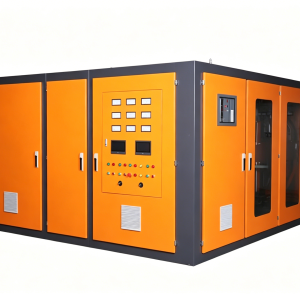
KGPS Induction Generator Power Supply
KGPS Induction Generator Power Supply for Industrial Melting and Forging
What Is the KGPS Induction Generator Power Supply?
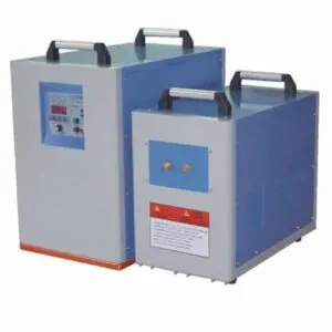
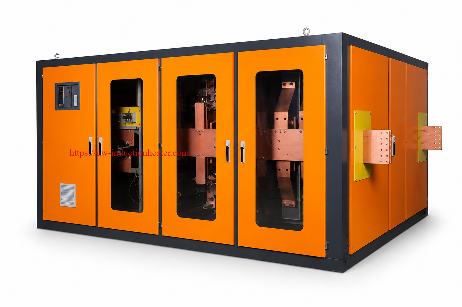
The HLQ KGPS Induction Generator Power Supply is a silicon-controlled rectifier (SCR/thyristor) medium-frequency power converter designed to energize matched induction coils for industrial metal melting, billet heating, forging preparation and selected thermal-processing applications. It converts industrial alternating-current input into controlled medium-frequency electrical power that generates eddy-current heating within conductive metal. The published HLQ range covers KGPS-200 through KGPS-1500, nominally 200–1500kW and 0.5–8kHz, with frequency and input voltage dependent on the model. The generator is one component of a complete heating installation; the coil or furnace, capacitors, cooling equipment, controls and material handling must be engineered for the actual process.
Quick Engineering Answer
| Buyer Question | Practical Answer |
|---|---|
| What is supplied? | KGPS medium-frequency generator; confirm whether capacitors, furnace, cooling and automation are included in the quotation. |
| Published nominal model range | KGPS-200 to KGPS-1500 (200–1500kW). |
| Published frequency range | 0.5–8kHz across the series, not 0.5–8kHz on every model. |
| Typical processes | Coreless induction melting; solid billet preheating for forging; selected large-section heating. |
| Critical design inputs | Material, charge or billet dimensions, real thermal load, target temperature, line voltage, cooling and duty cycle. |
| Key qualification | Request verified input/output power definitions, line power factor, actual operating frequency and full-load test results. |
For the wider selection context, compare HLQ’s
industrial induction heating power supply systems.
Key Applications
A KGPS generator is selected for the electrical and thermal characteristics of its load. A melting furnace and a continuous billet-heating line may use related medium-frequency power-conversion principles, but require different coils, mechanical systems and acceptance tests.
| Application | Typical Workpiece / Charge | Main Engineering Objective | Required Hardware |
|---|---|---|---|
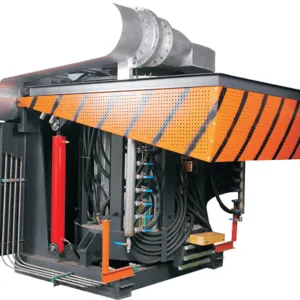
| Steel and cast-iron melting | Sorted ferrous charge in refractory crucible | Controlled melting, superheating and metal quality | Coreless furnace, refractory, tilting, cooling and safety monitoring |
| Copper and brass melting | Copper scrap, cathode, brass or alloy charge | Repeatable liquid-metal temperature and chemistry | Alloy-compatible crucible, fume control and pouring arrangement |
| Aluminum melting | Clean, dry aluminum charge | Melting without unnecessary superheat | Suitable furnace and melt-treatment equipment |
| Steel billet forging preheat | Solid round or square bars and billets | Achieve press-entry temperature and core uniformity | Through-heating coil, automatic feeder and pyrometer |
| Bar-end upsetting | Solid steel bars and rods | Heat only the required end length | Short induction coil, locating stop and temperature control |
| Selected large-part heating | Conductive metal sections | Controlled heat input before forming or treatment | Application-specific inductor and fixture |
For ferrous foundry applications, see HLQ’s
induction furnace for melting iron and steel.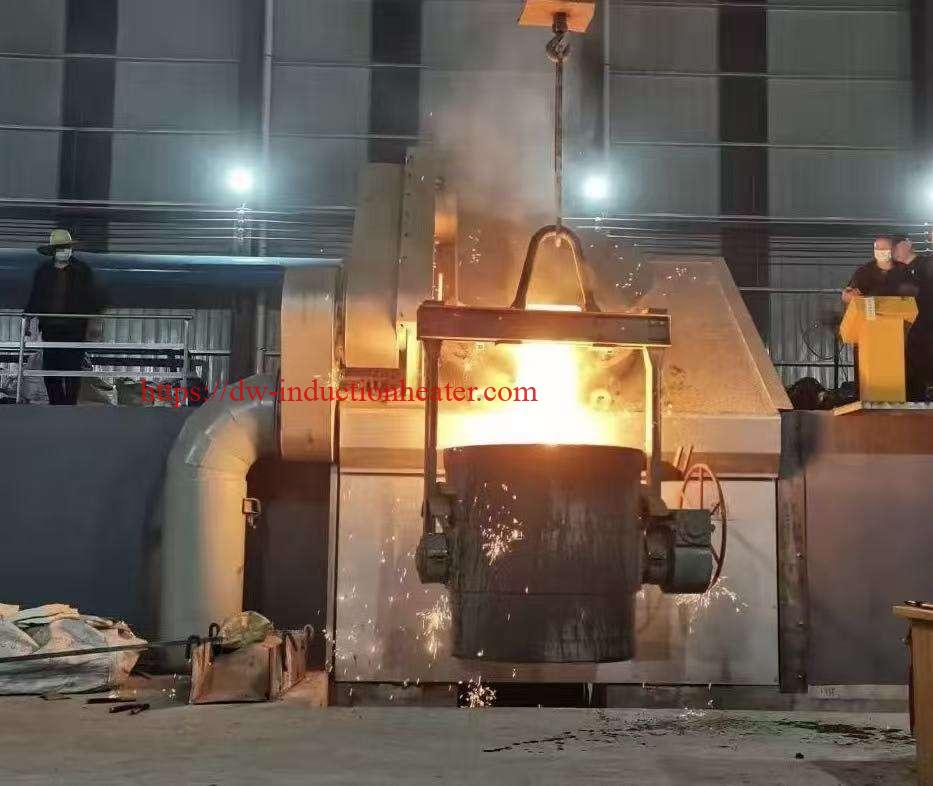
Suitable Materials
All electrically conductive metals can in principle be induction heated, but electrical resistivity, magnetic permeability, thermal conductivity, melting point and charge geometry determine the appropriate equipment and process. The values below are indicative application considerations, not validated heating recipes.
| Material | Typical KGPS Application | Engineering Consideration | Validation |
|---|---|---|---|
| Carbon steel | Billet forging; steel melting | Magnetic properties change near the Curie region; surface may heat before core. | Temperature profile, scale, grade-specific forging range. |
| Alloy steel | Forging preheat; alloy melting | Alloy-dependent temperature limits and metallurgical response. | Heat number, forming specification and core temperature. |
| Cast iron | Foundry melting | Composition control and furnace lining selection. | Chemistry, tapping temperature, specific kWh/t. |
| Stainless steel | Melting; selected through-heating | Different coupling and emissivity from carbon steel. | Coil matching and calibrated temperature measurement. |
| Copper | Melting; industrial heating | Very high conductivity and material-dependent hot resistivity. | Furnace efficiency, heat loss and oxidation control. |
| Brass | Melting; hot forming | Excessive temperature can increase zinc fume generation. | Alloy temperature window and ventilation. |
| Aluminum alloys | Melting; controlled billet heating | Grade-specific solidus and sensitivity to overheating. | Alloy-specific limit, thermocouple verification. |
Forging and Melting Are Different Thermal Duties
| Design Factor | Forging Preheat | Melting |
|---|---|---|
| Material at discharge | Solid | Liquid |
| Primary performance metric | kg/h at qualified uniform exit temperature | kg/batch, kWh/t and tap-to-tap cycle |
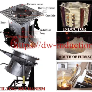
| Inductor configuration | Through-heating or localized coil | Furnace coil around refractory |
| Principal process risk | Core underheating or surface overheating | Molten-metal contact with water, refractory failure |
Working Principle
The KGPS system rectifies industrial AC electricity into controlled DC and converts it into medium-frequency AC for a matched induction load. Current through the copper induction coil generates an alternating magnetic field. Eddy currents induced in the metal dissipate energy as heat. Ferromagnetic alloys exhibit additional magnetic effects below the Curie temperature; however, thermal design must account for the strong change in permeability during heating.
Figure 1. KGPS Power Conversion and Load Matching
 THREE-PHASE AC INPUT
          |
          v
 +----------------------+    +---------------------+
 | SCR RECTIFIER        | -> | DC LINK / REACTOR   |
 +----------------------+    +---------------------+
                                      |
                                      v
                            +---------------------+
                            | THYRISTOR INVERTER  |
                            | KGPS CONTROL        |
                            +---------------------+
                                      |
                                      v
                            +---------------------+
                            | RESONANT CAPACITORS |
                            | MATCHED COIL        |
                            +---------------------+
                                      |
                     +----------------+----------------+
                     v                                 v
           SOLID BILLET HEATING                METAL MELTING FURNACE
           Eddy-current heating               Eddy-current heating
           Thermal equalization               Electromagnetic stirring

 SAFETY INTERLOCKS: cooling flow / phase loss / current / voltage
Frequency, Penetration and Temperature
For an approximately uniform conductor, the simplified electromagnetic skin depth is delta = sqrt[2rho/(2 pi f mu)], where rho is resistivity, f is frequency and mu is permeability. The approximation does not independently predict final core temperature in a hot, nonuniform steel billet.
| Published Frequency Band | KGPS Models | Selection Implication |
|---|---|---|
| 1–8kHz | KGPS-200, -250, -300 | Investigate smaller workpieces and appropriately designed loads; confirm coupling. |
| 1–4kHz | KGPS-400 | Application-dependent compromise between heating depth and equipment matching. |
| 0.5–2.5kHz | KGPS-500, -600, -750 | Evaluate larger charge sizes and billet cross-sections. |
| 0.5–1kHz | KGPS-800, -1000, -1200, -1500 | Typically associated with larger induction furnace loads; coil design remains decisive. |
Figure 2. Frequency vs. Simplified Skin Depth in Cold Copper
 COPPER AT ABOUT 20 C; rho = 1.72e-8 ohm*m; mu_r = 1

 0.5 kHz  |##############################|  2.95 mm
 1.0 kHz  |#####################         |  2.09 mm
 2.5 kHz  |#############                 |  1.32 mm
 4.0 kHz  |##########                    |  1.04 mm
 8.0 kHz  |#######                       |  0.74 mm

 Illustrative physics calculation only; not a coil-design guarantee.

Technical Specifications
The table below reproduces and clarifies the 11 published model rows on the HLQ KGPS product page. The source calls the current “inlet current” and labels the kW values “power rate” without specifying whether they are AC real input, DC-link power or inverter output. Therefore, the nominal kW ratings are model designations pending factory confirmation, not independently measured full-load results. The source describes 50Hz input and mentions three- or six-phase input arrangements; the phase and transformer design must be verified by model.
General Specifications
| Parameter | Specification | Notes |
|---|---|---|
| Series | KGPS SCR / thyristor induction generator | Medium-frequency power source |
| Published model range | KGPS-200 to KGPS-1500 | 11 model rows |
| Published nominal power | 200–1500kW | Definition of rated kW must be confirmed |
| Output frequency | 0.5–8kHz across the series | Model-dependent ranges |
| Published input voltage | 380V, 660V and one 750V variant | 50Hz stated; confirm 60Hz if required |
| Published inlet current | 320–1400A, model-dependent | Some alternative voltage/current pairings require verification |
| Power regulation | Described as constant-capacity control | Confirm actual constant-power range and tolerances |
| Starting | Frequency-sweep, zero-voltage start claimed | Confirm sequence and compatibility with furnace/load |
| Protection listed | Overcurrent, undercurrent, overvoltage, undervoltage, water shortage and phase fault | Setpoints and tested actions not published |
| Cooling flow / pressure | Not published on this model page | Must be defined for the full package |
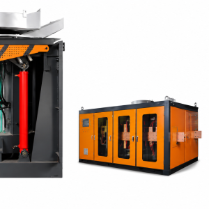
| Capacitor cabinet / coil / furnace | Not defined as included | Specify purchase scope explicitly |
| Continuous duty / efficiency / power factor | Not established by model table | Require rated-condition test documents |
Published KGPS Model Comparison
| Model | Input Voltage (V) | Published Inlet Current (A) | Frequency (kHz) | Nominal Power (kW) |
|---|---|---|---|---|
| KGPS-200 | 380 | 320 | 1–8 | 200 |
| KGPS-250 | 380 | 400 | 1–8 | 250 |
| KGPS-300 | 380 | 480 | 1–8 | 300 |
| KGPS-400 | 380 | 640 | 1–4 | 400 |
| KGPS-500 | 380 | 800 | 0.5–2.5 | 500 |
| KGPS-600 | 380 | 1000 | 0.5–2.5 | 600 |
| KGPS-750 | 380 | 1200 | 0.5–2.5 | 750 |
| KGPS-800 | 380 / 660 | 1300 / 730 | 0.5–1 | 800 |
| KGPS-1000 | 660 | 920 | 0.5–1 | 1000 |
| KGPS-1200 | 660 | 1100 | 0.5–1 | 1200 |
| KGPS-1500 | 660 / 750 | 1400 / 600 | 0.5–1 | 1500 |
Important discrepancy: For KGPS-1500, the published 750V / 600A pairing corresponds to only about 779kVA of three-phase apparent input power, which cannot sustain 1500kW of real electrical input. The 750V/600A entry must be corrected or explained before it is used in a quotation. Do not silently treat it as a verified 1500kW rating.
Three-Phase Electrical Cross-Check
S(kVA) = sqrt(3) x V(line-to-line) x I(line) / 1000 and P_real(kW) = S(kVA) x true power factor, for an appropriately measured balanced three-phase supply. Power factor is never greater than 1.
| Published Voltage / Current | Calculated Apparent Input | Corresponding Model | Engineering Interpretation |
|---|---|---|---|
| 380V / 320A | 211kVA | KGPS-200 | 200kW line input would need PF about 0.95. |
| 380V / 800A | 527kVA | KGPS-500 | 500kW line input would need PF about 0.95. |
| 660V / 920A | 1052kVA | KGPS-1000 | 1000kW line input would need PF about 0.95. |
| 660V / 1400A | 1600kVA | KGPS-1500 option | Numerically possible if line PF and rating definition are confirmed. |
| 750V / 600A | 779kVA | KGPS-1500 option | Insufficient to represent 1500kW real input; verify published entry. |
Recommended Model Selection
First estimate the thermal requirement, then validate the appropriate frequency range, coil design, electrical input and full-load performance. The following forging examples assume carbon steel heated from about 20°C to about 1100°C, a specific enthalpy rise of 750kJ/kg, 65% overall electrical-to-workpiece efficiency and 15% design allowance. These are calculation assumptions, not tested KGPS efficiencies.
| Application | Material | Recommended Power | Frequency |
|---|---|---|---|
| 500kg/h billet preheat | Carbon steel | 184kW calculated incl. allowance; evaluate KGPS-200 | KGPS-200: published 1–8kHz; match to billet diameter |
| 800kg/h forging feed | Carbon steel | 295kW calculated incl. allowance; evaluate KGPS-300 | KGPS-300: published 1–8kHz; verify core heating |
| 1000kg/h forging line | Carbon steel | 369kW calculated incl. allowance; evaluate KGPS-400 | KGPS-400: published 1–4kHz |
| 1500kg/h forging line | Carbon / alloy steel | 553kW calculated incl. allowance; evaluate KGPS-600 | KGPS-600: published 0.5–2.5kHz |
| 2000kg/h forging line | Carbon steel | 737kW calculated incl. allowance; evaluate KGPS-750 | KGPS-750: published 0.5–2.5kHz |
| 2500kg/h forging line | Carbon steel | 922kW calculated incl. allowance; evaluate KGPS-1000 | KGPS-1000: published 0.5–1kHz |
| Ferrous melting | Steel / cast iron | Choose from measured kWh/t, charge and target tap-to-tap time | Match the actual furnace coil and melt load |
| Nonferrous melting | Copper / brass / aluminum | Choose from alloy-specific measured melting energy | Match coil, crucible and charge geometry |
A model is not approved solely because its published nominal kW exceeds a heat-balance calculation. Continuous line power, converter losses, resonant matching, actual coil coupling, workpiece thermal gradients and the available transformer must also be verified.
Process Workflow
Figure 3. Engineering-to-Commissioning Workflow
 CUSTOMER PROCESS DEFINITION
  Material | Dimensions | kg/h or kg/batch
                 |
                 v
 HEAT LOAD + FREQUENCY STUDY
                 |
                 v
 SELECT KGPS GENERATOR / LINE SUPPLY
                 |
                 v
 DESIGN CAPACITORS + COIL / FURNACE
                 |
                 v
 DESIGN COOLING + ELECTRICAL PROTECTION
                 |
                 v
 BUILD AND COMMISSION
                 |
                 v
 MEASURE TRUE kW + kWh + TEMPERATURE
                 |
                 v
 PRODUCTION TRIAL + ACCEPTANCE TEST
Production Workflow: Forging vs. Melting
| Stage | Forging Line | Melting Furnace |
|---|---|---|
| Incoming material | Confirm steel grade, dimensions, individual billet mass | Sort charge, remove prohibited contaminants and moisture |
| Load handling | Feed aligned billets into coil | Charge refractory-lined furnace safely |
| Power application | Control billet residence time and generator power | Control melting, holding and superheating |
| Process measurement | Measure exit temperature; validate core on trials | Measure liquid-metal temperature and chemistry |
| Discharge | Transfer to forging press | Pour using approved tilting procedure |
| Production record | Pieces/h, kg/h, kWh/t, reject temperature alarms | Charge weight, kWh/t, tap-to-tap time, temperature |
Coil and Fixture Design
Power-supply selection alone cannot determine coil turns, coil dimensions or compensating capacitance. These parameters form an electrically coupled resonant system and should be engineered together. Forging coils and melting-furnace coils must not be assumed interchangeable.
| Design Item | Forging Inductor | Melting Furnace Coil |
|---|---|---|
| Geometry | Helical through-coil or localized heating coil | Coil surrounds refractory-lined crucible |
| Load movement | Solid billet typically advances through coil | Charge remains in furnace until pouring |
| Matching focus | Changing billet position, cross-section and temperature | Changing melt level and molten electrical load |
| Insulation | Protective liners and adequate clearances | High-temperature refractory and ground-fault strategy |
| Mechanical design | Guides, pusher, stops and thermal expansion | Furnace structure, magnetic yokes, tilting mechanism |
| Safety | Feeder and guarding interlocks | Lining integrity, spill protection and wet-charge exclusion |
Cooling Circuit Heat-Balance Examples
For water around typical industrial temperatures: Q(kW) = 1.163 x Flow(m3/h) x Water Rise(C). These are calculated water-side loads and are not published HLQ cooling requirements.
| Assumed Flow (m3/h) | Temperature Rise | Calculated Heat Removed | Implication |
|---|---|---|---|
| 5 | 5°C | 29kW | Check generator and coil branch flow separately. |
| 10 | 5°C | 58kW | Cooling method must reject at least actual measured losses. |
| 20 | 5°C | 116kW | Pump pressure and return temperature remain important. |
| 30 | 5°C | 174kW | Do not infer adequate cooling from flow alone. |
Specify water conductivity, hardness, pressure, inlet temperature, strainers, flow switches and separate flow verification for critical branches. Low-water-flow events must initiate the designed electrical response; do not automatically stop necessary emergency cooling of a hot furnace.
Control System and Automation
The original page claims constant-capacity regulation, frequency-sweep starting and protection against overcurrent, undercurrent, overvoltage, undervoltage, water shortage and phase faults. It does not establish a specific PLC brand, communication protocol, power-factor performance or complete automatic line-control package.
| Control / Protection | Process Purpose | Status / Required Verification |
|---|---|---|
| SCR power regulation | Match thermal power demand | Claimed; verify measured regulation range |
| Frequency-sweep start | Initiate resonant operation with compatible load | Claimed; test start under agreed conditions |
| Overcurrent and undervoltage | Protect converter and connected system | Claimed; test alarm thresholds |
| Phase-loss / abnormal input | Prevent unsafe operation | Claimed; verify line protection and sequence |
| Cooling-flow interlock | Protect coil and power electronics | Claimed in general; verify each critical branch |
| Real kW and kWh meter | Validate performance and operating cost | Recommended instrumentation; inclusion unconfirmed |
| Billet pyrometer feedback | Control forging exit temperature | Optional system-level design |
| Furnace temperature / chemistry | Support controlled melting and pouring | Separate instrumentation required |
| PLC/HMI and data logging | Recipe, alarms, production traceability | Quote-specific, not assumed standard |
Common Problems and Solutions
| Observed Problem | Potential Cause | Engineering Response |
|---|---|---|
| Power will not start | Cooling interlock, input fault, failed resonant start | Read fault log; inspect by qualified personnel after isolation |
| Frequent overcurrent trips | Coil short, poor load match or component fault | Check coil insulation, resonance and factory diagnostic sequence |
| Unstable operating frequency | Load geometry or capacitor bank mismatch | Record actual frequency, current and capacitor condition |
| Low measured real power | Supply limitation, PF, incorrect meter or power regulation | Measure true three-phase input kW, kVA, PF and harmonics |
| Billet surface hot, core cold | Insufficient penetration / residence time | Change coil design, staging or equalization; validate core temperature |
| Melting takes too long | Low sustained kW, hot/cold start effects or charge issues | Measure complete energy and tap-to-tap cycle |
| Coil or busbar overheats | Insufficient flow, poor joints or excessive current | Isolate safely, inspect cooling, connections and losses |
| Capacitor overheating | Excessive reactive current or poor cooling | Verify capacitor rating, matching and thermal condition |
| Water flow alarm | Blocked strainer, pump fault, leakage or sensor issue | Measure branch flow and restore safe cooling |
| Refractory deterioration | Thermal cycling, incorrect lining or mechanical damage | Stop affected furnace; follow inspection and relining procedure |
| Wet charge in melting furnace | Moisture or sealed contaminated scrap | Prevent charging and follow site molten-metal safety procedures |
Engineering Selection Guide
1. Calculate Real Heating Power for Steel Billets
For continuous processing:
P_in(kW) = Throughput(kg/h) x Delta-h(kJ/kg) / [3600 x overall efficiency].
This example assumes 750kJ/kg to heat carbon steel from about 20°C to 1100°C and 65% overall electrical-to-workpiece efficiency.
| Steel Throughput | Useful Thermal Power | Estimated Real Input at 65% | Plus 15% Allowance |
|---|---|---|---|
| 500kg/h | 104kW | 160kW | 184kW |
| 800kg/h | 167kW | 256kW | 295kW |
| 1000kg/h | 208kW | 321kW | 369kW |
| 1500kg/h | 313kW | 481kW | 553kW |
| 2000kg/h | 417kW | 641kW | 737kW |
| 2500kg/h | 521kW | 801kW | 922kW |
Figure 4. Estimated Forging Power vs. Throughput
 CARBON STEEL 20 -> 1100 C; 750kJ/kg; assumed eta = 65%

 INPUT REAL POWER, WITHOUT 15% DESIGN ALLOWANCE

  500kg/h   |######                         | 160kW

  800kg/h   |##########                     | 256kW

 1000kg/h   |#############                  | 321kW

 1500kg/h   |###################            | 481kW

 2000kg/h   |##########################     | 641kW

 2500kg/h   |################################| 801kW

 CALCULATED EXAMPLES, NOT KGPS FACTORY PERFORMANCE DATA

2. Estimate Batch Melting Time
Electrical energy (kWh) = Melt weight (tonnes) x Specific electrical consumption (kWh/t).
Idealized energized time (hours) = Energy / Sustained measured real input kW.
The following uses 650kWh/t as an illustrative total electrical consumption for an example ferrous-melting duty. It is not a guarantee for any KGPS model.
| Charge | Assumed Input Energy | Assumed Sustained Real Power | Idealized Energized Time |
|---|---|---|---|
| 250kg | 162.5kWh | 250kW | 39min |
| 500kg | 325kWh | 400kW | 49min |
| 1000kg | 650kWh | 800kW | 49min |
| 1500kg | 975kWh | 1200kW | 49min |
The simple time calculation assumes that the quoted kWh/t and average power cover comparable operating boundaries. Real tap-to-tap time may include charging, chemistry adjustment, sampling, waiting and pouring. A furnace nameplate kW value must not be substituted for measured sustained real input without verification.
3. Validate Factory Line Power and Transformer Capacity
| Input Check | Engineering Requirement | Required Evidence |
|---|---|---|
| Voltage and frequency | Match local electrical network | Transformer and supply specification |
| Three-phase input current | Not exceed approved feeders and devices | Measured RMS line currents |
| Real power vs. apparent power | Respect P <= S | True kW, kVA and power-factor recording |
| Harmonics | Meet site and grid requirements | Electrical study and measured current distortion |
| Cooling losses | Provide adequate heat rejection | Measured flows, temperatures and pressure |
| Generator operation | Stable at expected load | Power/frequency trace at operating temperature |
4. Commissioning and Factory Acceptance Test
| Acceptance Item | Measurement | Pass Basis |
|---|---|---|
| Power supply model | Nameplate and wiring drawing | Ordered KGPS configuration |
| Electrical output | Input kW, current, voltage and operating frequency | Agreed and independently verifiable test conditions |
| Forging duty | kg/h, billet exit and core temperature | Documented forging specification |
| Melting duty | Charge weight, kWh/t, melt time and temperature | Documented melting acceptance test |
| Process repeatability | Successive representative batches | Agreed production tolerance |
| Cooling protection | Flow, pressure, alarms and safe response | Approved safety design |
| Final documentation | Electrical, cooling and operating manuals | Signed acceptance record |
Advantages
| Potential Advantage | Operational Benefit | Qualification |
|---|---|---|
| Industrial medium-frequency output | Supports appropriately matched heavy induction loads | Confirm actual power and frequency under load |
| SCR technology | Established power-conversion approach for industrial furnaces | Compare service access, spares and electrical performance |
| Process flexibility | Candidate for melting, forging preheat and heating | Each application requires dedicated load engineering |
| Range of nominal power classes | 200–1500kW published options | Verify apparent-power inconsistencies |
| Protection functions | Supports fault identification and safe operating limits | Verify settings, sensors and interlock tests |
| Automation compatibility | Possible integration with temperature and production controls | Requires explicitly quoted interfaces |
Limitations
| Limitation | Why It Matters | Recommended Action |
|---|---|---|
| Power definition unclear | Model kW label may not equal measured real line input or coil output | Request a certified full-load electrical test |
| KGPS-1500 750V/600A conflict | Calculated apparent input is less than claimed 1500kW | Correct the factory model table before quotation |
| Frequency varies by model | Not every model can provide 8kHz | Select by actual coil/load frequency |
| Generator is not a complete furnace | Coil, crucible, handling and cooling may be excluded | Demand detailed scope of supply |
| High electrical infrastructure demand | Feeders, transformer, reactive power and harmonics matter | Perform site electrical study |
| Thermal nonuniformity | Large billets can have hot surface and cold core | Conduct temperature and residence-time trials |
| Molten-metal hazards | Wet charge and water ingress can cause violent events | Use validated furnace safety and emergency procedures |
| Unpublished cooling performance | Cannot specify chiller from power rating alone | Obtain measured water-side losses and pump data |
Why Choose HLQ Induction Equipment?
HLQ supplies induction heating generators and related equipment for industrial metal processing. For a KGPS project, engineering value comes from pairing the correct electrical generator with a validated furnace or forging coil, reliable cooling, suitable site power, and measurable process acceptance criteria. Buyers should request current model drawings, verified electrical ratings, integration details, spare-parts information and a test protocol using their own workpiece or charge material.
For application-specific packages, explore HLQ’s
induction forging bar and billet furnaces,
copper induction melting furnaces
and
industrial induction melting furnace systems.
Information Required for a Technical Quotation
| Customer Input | What to Specify |
|---|---|
| Application | Melting / forging preheat / bar-end heating / other |
| Material | Exact grade, charge condition and cleanliness |
| Workpiece | Diameter, section, length and weight; or furnace charge per batch |
| Temperature | Initial, target, allowable gradient and pouring/forging conditions |
| Output | kg/h, pieces/h, or tons per day with target cycle |
| Electrical utilities | Available line voltage, 50/60Hz, transformer rating, site PF limits |
| Cooling | Water quality, temperature, flow, pressure and redundancy |
| Supply scope | Generator only or complete system including capacitors and load |
| Acceptance | Measured real power, specific kWh/t, production rate and temperature |
Core FAQs
FAQ 1. What is a KGPS induction generator power supply?
It is an SCR/thyristor-based medium-frequency power converter that drives a matched induction coil. It is commonly applied to industrial metal melting and solid-metal heating. The generator itself does not automatically include a complete furnace, refractory lining or material handling system.
FAQ 2. Which KGPS models and frequencies are published by HLQ?
The reviewed product page lists 11 models from KGPS-200 to KGPS-1500, with nominal power labels from 200 to 1500kW. Models KGPS-200/250/300 show 1–8kHz; KGPS-400 shows 1–4kHz; KGPS-500/600/750 show 0.5–2.5kHz; and KGPS-800/1000/1200/1500 show 0.5–1kHz.
FAQ 3. Does the published 1500kW model require technical clarification?
Yes. One original KGPS-1500 entry pairs 750V with 600A. In a balanced three-phase calculation, this is about 779kVA, so it cannot represent 1500kW real electrical input at that voltage and current. The manufacturer should issue a corrected and tested rating.
FAQ 4. How much power is required to heat 1000kg/h of carbon steel for forging?
With illustrative assumptions of 750kJ/kg enthalpy rise and 65% overall electrical-to-workpiece efficiency, estimated average real input is about 321kW. With 15% planning allowance, the preliminary requirement is about 369kW. This does not confirm that a particular coil or KGPS model meets the required core temperature.
FAQ 5. How should frequency be selected for a steel billet or melting furnace?
Frequency must be matched to workpiece or charge geometry, metal properties, resonant circuit, penetration and production cycle. Larger furnace charges often use lower frequencies, while smaller heating zones may require higher frequencies. Validate the final design through electrical and thermal trials.
FAQ 6. What is the difference between a KGPS SCR generator and an IGBT induction generator?
A KGPS generator uses thyristor/SCR conversion, while an IGBT generator uses insulated-gate bipolar transistor switching. The control architecture, typical switching frequencies, power matching and maintenance requirements differ. Selection should be based on a specific thermal load and verified system performance, not on semiconductor names alone.
FAQ 7. How should cooling equipment be sized?
Size cooling equipment from actual heat rejected into each cooling-water circuit, required flow, inlet temperature, pressure loss and water-quality specifications. For water, Q(kW) is approximately 1.163 times flow in m3/h times water temperature rise in degrees Celsius. The KGPS product page does not publish sufficient model-specific cooling data to calculate a guaranteed chiller size.
FAQ 8. What should be checked before purchasing a complete KGPS induction system?
Confirm the exact model, correct electrical input and kW definition, load frequency, site transformer, capacitor bank, matching coil or furnace, cooling equipment, protection interlocks, automation scope and installation requirements. Demand a written factory acceptance test based on measured input power, production output, process temperature and specific electrical consumption.