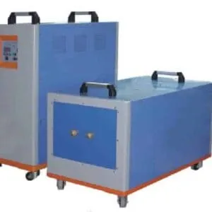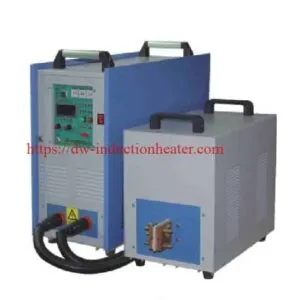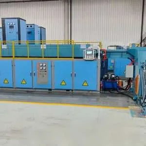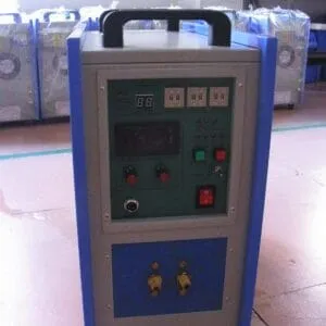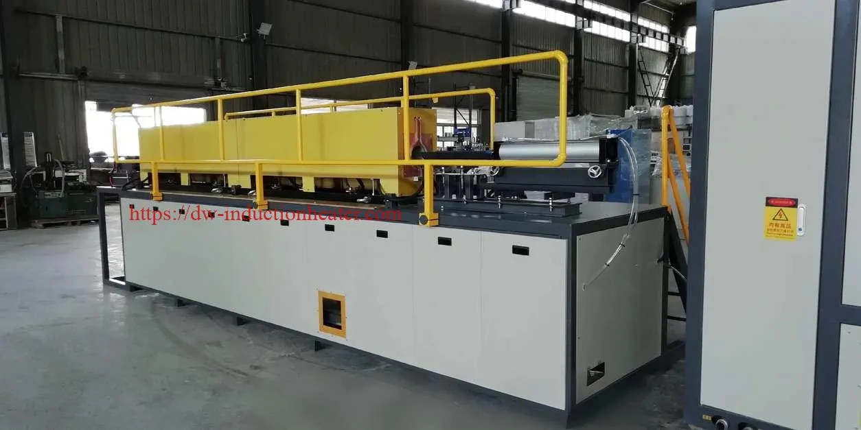
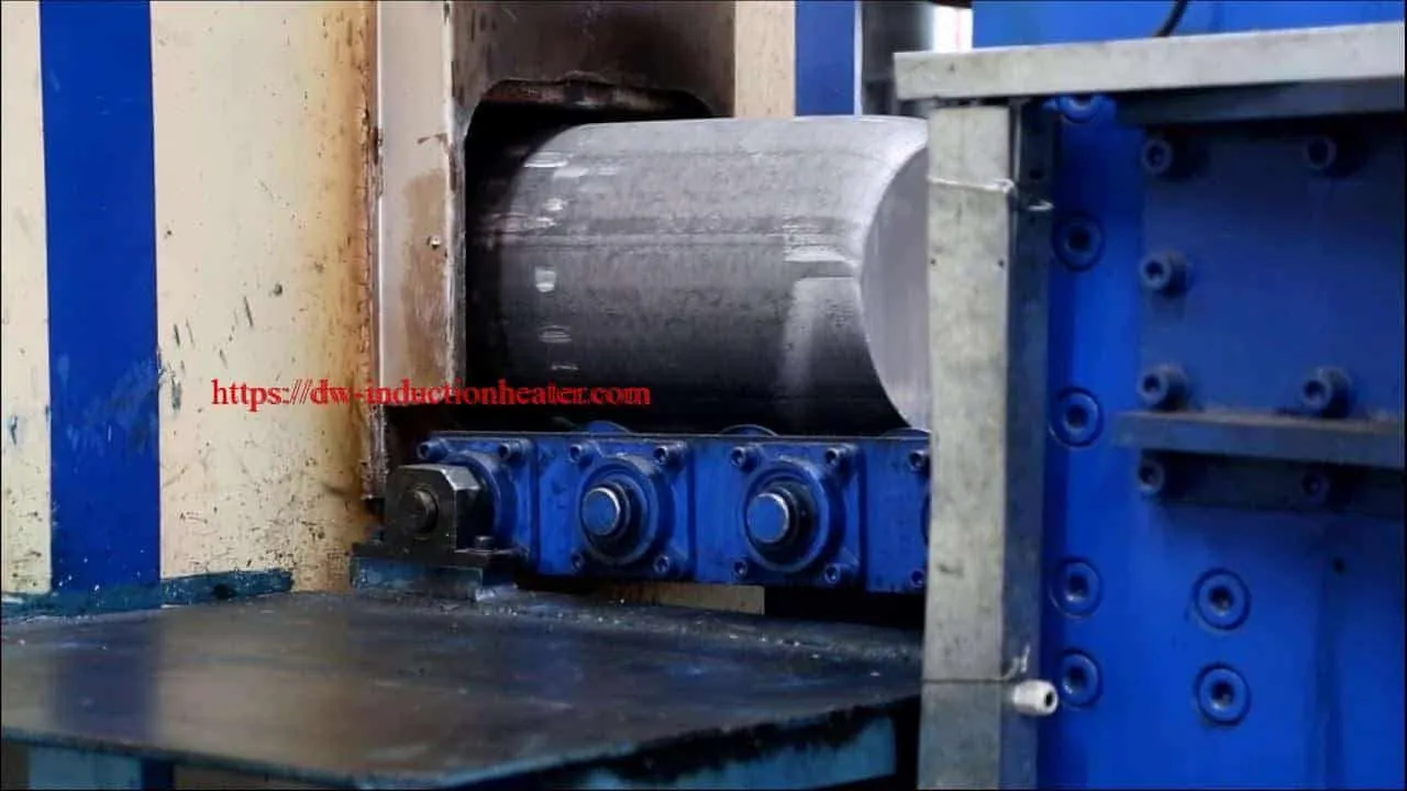
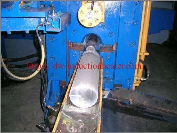
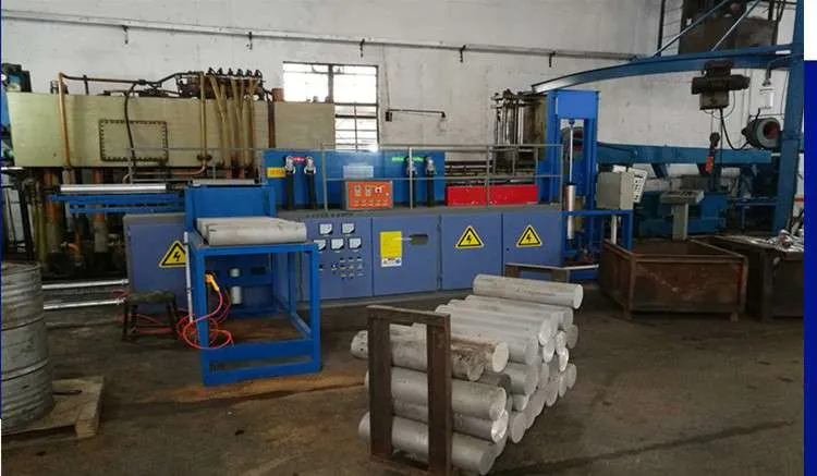
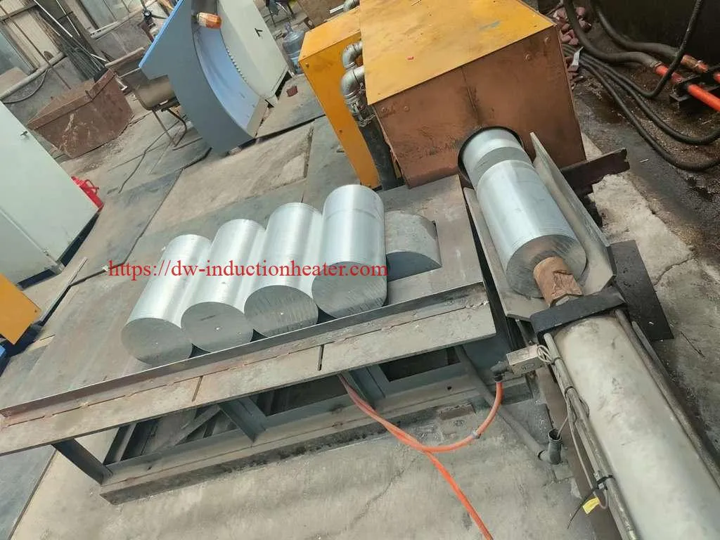
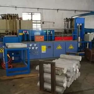

Aluminium Billet Induction Heater for Extrusion Energy Efficient Metals Heating Solution
Aluminum Billet Induction Heater for Extrusion
What Is an Aluminum Billet Induction Heater for Extrusion?
Where Billet Heating Fits in the Extrusion Process
How Does Aluminium Billet Induction Heating Work?
The Core Physics — Explained Simply
Why Aluminium Is Uniquely Challenging for Induction Heating
Skin Depth and Frequency Selection
The Game-Changer: Gradient (Taper) Heating for Extrusion
The Problem: Why Uniform Heating Is Suboptimal for Extrusion
The Solution: Gradient (Taper) Heating
The Measurable Benefits of Gradient Heating
How Induction Systems Create Gradient Profiles
Types of Aluminium Billet Induction Heating Systems
- Continuous Multi-Coil Inline Heaters
- Single-Station Static Heaters
- Log Heaters (Pre-Cut Heating)
- Dual-Strand Parallel Systems
Technical Specifications: What the Numbers Mean
Temperature Control Specifications
Energy Efficiency: The Numbers That Justify the Investment
Where Gas Furnaces Lose Energy
Real-World Energy Cost Comparison
Surface Quality and Scale Reduction
The Scale Problem with Gas Heating
Induction Heating’s Clean Advantage
System Integration with the Extrusion Press
Critical Integration Requirements
Installation and Infrastructure Requirements
Electrical Supply Requirements
Aluminum Billet Induction Heater for Extrusion
If you run an aluminum extrusion operation, you already know that everything starts with the billet. The press, the die, the cooling system — all of it depends on one thing happening correctly first: heating the billet to exactly the right temperature, in exactly the right way.
For decades, gas-fired furnaces were the only option. Today, aluminum billet induction heaters have transformed how extrusion plants around the world heat their billets — delivering faster heating, tighter temperature control, lower energy costs, better surface quality, and longer die life.
This guide covers everything: how induction heating works for aluminum extrusion, why gradient heating is the game-changer, how to calculate the right system size, and how to choose the best supplier for your operation.
What Is an Aluminum Billet Induction Heater for Extrusion?
An aluminum billet induction heater is a purpose-built industrial heating system that uses electromagnetic induction to heat solid aluminum billets to their optimal extrusion temperature — typically 450°C to 530°C — before they are loaded into the extrusion press container.
The fundamental difference from gas heating: induction heaters generate heat directly inside the billet itself through induced electrical currents, rather than heating the billet from the outside through convection and radiation from a gas flame.
The practical result:
- Faster heating — minutes instead of hours
- More uniform temperature — throughout the billet cross-section
- Precise gradient control — front-to-back temperature profiling
- Less oxidation — dramatically reduced scale formation
- Lower energy cost — 60–80% system efficiency vs. 30–45% for gas
Where Billet Heating Fits in the Extrusion Process
Raw Aluminium Log / Billet (room temperature)
↓
┌─────────────────────────┐
│ Induction Billet Heater │ ← This guide focuses here
│ (450°C – 530°C) │
└─────────────────────────┘
↓
Extrusion Press Container
(billet loaded, ram advances)
↓
Die (aluminium flows through profile shape)
↓
Runout Table (profile exits, cooled by air/water)
↓
Stretcher (straightening)
↓
Age Oven (artificial ageing for T5/T6 temper)
↓
Finished Aluminium Profile
Every stage downstream of heating is largely mechanical and fixed. But the temperature, uniformity, and gradient of the heated billet directly control:
- Press tonnage required per stroke
- Maximum achievable extrusion speed
- Surface finish quality of the profile
- Dimensional consistency along the full profile length
- Die wear rate and service life
- Scrap rates and end-crop losses
Get the heating right, and every downstream process becomes easier and more profitable. Get it wrong, and no press optimization will fix the problems.
How Does Aluminium Billet Induction Heating Work?
The Core Physics — Explained Simply
Induction heating is based on two well-established laws of physics:
Faraday’s Law of Electromagnetic Induction:
A changing magnetic field induces an electrical current in any conductive material within that field.
Joule’s Law of Heating:
When an electrical current flows through a material with electrical resistance, it generates heat (P = I²R).
Put them together, and you have induction heating:
Step 1: AC power supply generates high-frequency
alternating current (1,000–3,000 Hz for aluminium)
↓
Step 2: Current flows through water-cooled copper coil,
creating alternating electromagnetic field
↓
Step 3: Aluminium billet placed inside coil —
magnetic field induces eddy currents in billet
↓
Step 4: Eddy currents meet electrical resistance of aluminium,
converting energy to heat (I²R heating)
↓
Step 5: Heat conducts from outer zone to billet core,
achieving uniform temperature distribution
↓
Result: Billet heated to target temperature
from the inside out — no flame required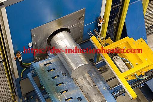
Why Aluminium Is Uniquely Challenging for Induction Heating
Aluminium has physical properties that make induction heating both technically demanding and highly rewarding:
| Property | Value | Impact on Induction Heating |
| Electrical resistivity | 2.65 × 10⁻⁸ Ω·m | Low — requires higher power density |
| Relative permeability | ~1.0 (non-magnetic) | No magnetic enhancement of coupling |
| Thermal conductivity | 205 W/(m·K) | Excellent — promotes fast, uniform heat distribution |
| Specific heat capacity | 900 J/(kg·°C) | Moderate energy requirement per kg |
| Melting point | 660°C | Only ~130–200°C above extrusion temperature — precise control essential |
| Solidus temperature (6063) | ~615°C | Hard upper limit — overheating causes partial melting |
Because aluminium is non-magnetic and highly electrically conductive, it requires:
- Higher operating frequencies (1,000–3,000 Hz) compared to steel billet heating
- Higher power densities to achieve practical heating rates
- Extremely precise temperature control — the window between optimal extrusion temperature and incipient melting is narrow
These challenges are fully solved by modern induction system designs. In fact, aluminium’s excellent thermal conductivity is a major advantage — once heat is generated in the outer zone, it distributes rapidly and evenly to the billet core.
Skin Depth and Frequency Selection
One of the most important technical parameters in induction heating design is skin depth — the depth below the billet surface where most of the induced current (and therefore heat) is generated.
Skin Depth Formula:
δ = 503 × √(ρ / μr × f)
Where:
δ = skin depth (mm)
ρ = electrical resistivity (Ω·m)
μr = relative permeability
f = frequency (Hz)
Calculated skin depths for aluminium at 500°C:
| Frequency | Skin Depth | Best Billet Diameter Range |
| 500 Hz | ~48mm | Up to 150mm diameter |
| 1,000 Hz | ~34mm | 100mm – 200mm diameter |
| 1,500 Hz | ~28mm | 100mm – 200mm diameter |
| 2,000 Hz | ~24mm | 75mm – 175mm diameter |
| 3,000 Hz | ~19mm | 75mm – 150mm diameter |
For the most common aluminium extrusion billet diameters (100mm–300mm), 1,000–2,000 Hz delivers the optimal balance of penetration depth and heating efficiency.
For larger billets (250mm–400mm), lower frequencies (500–1,000 Hz) ensure adequate core heating without relying entirely on thermal conduction.
The Game-Changer: Gradient (Taper) Heating for Extrusion
If there is one single feature that defines a truly capable aluminium billet induction heater for extrusion — one that separates a competent system from an exceptional one — it is gradient heating.
Understanding gradient heating is essential for any extrusion plant evaluating induction technology.
The Problem: Why Uniform Heating Is Suboptimal for Extrusion
At first glance, heating a billet to a perfectly uniform temperature throughout its length seems like the ideal outcome. In aluminium extrusion, it is not.
Here is what actually happens during an extrusion stroke:
Start of Stroke:
Billet temperature: uniform at 500°C throughout
Ram pressure: moderate
Extrusion speed: target speed achievable
Mid Stroke:
Front portion of billet has already passed through die
Remaining billet: still at 500°C (uniform)
Ram pressure: increasing (billet cooling, flow stress rising)
Extrusion speed: starting to slow
End of Stroke:
Only rear portion of billet remains
Temperature: billet has lost heat through die contact
Ram pressure: significantly higher
Extrusion speed: well below target — or press stops
The result of uniform heating:
- Variable press force throughout the stroke
- Inconsistent extrusion speed — profile dimensions vary along length
- More end-crop scrap — profile start and end sections out of tolerance
- Reduced die life — pressure spikes accelerate die wear
- Lower productivity — average speed limited by worst-case conditions
The Solution: Gradient (Taper) Heating
Gradient heating means deliberately creating a front-to-back temperature difference in the billet before it enters the press — typically 20°C to 60°C hotter at the front than the rear.
code<button><svg><path></path></svg><span>Copy code</span><span></span></button>
Gradient-Heated Billet Temperature Profile:
Front End ◄────────────────────────► Rear End
530°C 520°C 510°C 495°C 480°C
████████████████████████████████████
Hotter ──────────────────► Cooler
Temperature gradient: 50°C front-to-back
As extrusion proceeds with a gradient-heated billet:
Start of Stroke:
Front (530°C) enters die first
Higher temperature = lower flow stress = lower press force
Extrusion speed: at target
Mid Stroke:
Middle sections (505°C) now entering die
Temperature compensates for heat loss
Press force: remains stable
Extrusion speed: maintained at target
End of Stroke:
Rear sections (480°C) entering die
Cooler temperature compensates for retained heat in die
Press force: remains stable
Extrusion speed: maintained at target throughout
The Measurable Benefits of Gradient Heating
| Performance Metric | Without Gradient | With Gradient | Improvement |
| Extrusion speed consistency | Variable ±15–25% | Consistent ±3–5% | Dramatically better |
| Average extrusion speed | Baseline | +10–25% faster | Significant gain |
| Ram pressure variation | High | Low | Reduced die stress |
| Profile dimensional tolerance | Wider | Tighter | Better quality |
| End-crop scrap length | Longer | Shorter | 20–40% less scrap |
| Die service life | Baseline | +15–35% longer | Major cost saving |
| Surface finish consistency | Variable | Consistent | Fewer defects |
How Induction Systems Create Gradient Profiles
Modern aluminium billet induction heaters use multiple independently controlled heating zones along the billet length:
┌──────────────┬──────────────┬──────────────┐
│ Zone 1 │ Zone 2 │ Zone 3 │
│ (Front) │ (Middle) │ (Rear) │
│ │ │ │
│ High Power │ Medium Power │ Low Power │
│ 530°C │ 510°C │ 480°C │
└──────────────┴──────────────┴──────────────┘
↑ ↑ ↑
Independent Independent Independent
Power Control Power Control Power Control
Each zone has its own power supply output control, enabling operators to program:
- Linear gradients — smooth, uniform temperature ramp along billet length
- Step gradients — abrupt temperature change at a specific point
- Custom profiles — complex gradient curves matched to specific alloy behavior and die design
- Flat profiles — uniform temperature when gradient is not required
Gradient profiles are stored as digital recipes — one per alloy/billet size/die combination. Operators simply select the recipe, and the system configures itself automatically.
Types of Aluminium Billet Induction Heating Systems
The standard configuration for production extrusion plants worldwide.
How it works:
Billets are automatically fed sequentially through a series of induction coil stations on a powered conveyor. Each station contributes to progressive heating. The final zone provides gradient profile trimming. Heated billets exit directly to the press loading station.
System layout:
[Billet Magazine] → [Entry Conveyor] → [Coil 1] → [Coil 2] →
[Gradient Zone] → [Exit Pyrometer] → [Reject Gate] → [Press]
Key advantages:
- ✅ Fully automated — minimal operator intervention
- ✅ Continuous production — no interruption between billets
- ✅ Synchronized with press cycle automatically
- ✅ Multiple gradient profiles stored as recipes
- ✅ Automatic under-temperature rejection
- ✅ Full data logging for quality traceability
Best for: High-volume extrusion plants, 24/7 operations, multiple alloy processing
A simpler configuration where each billet is loaded individually into a single coil station, heated, then transferred to the press.
Key advantages:
- ✅ Lower capital cost
- ✅ Simpler installation
- ✅ Suitable for lower production volumes
Limitations:
- ❌ Lower production rate
- ❌ Less automation
- ❌ Limited gradient capability
Best for: Smaller extrusion operations, lower volumes, R&D applications
Designed to heat full-length aluminium logs (3–7 meters) before hot saw cutting into individual billets.
Key advantages:
- ✅ Higher material yield (hot cutting is more precise)
- ✅ Eliminates cold saw operation before heating
- ✅ Better for very high-volume continuous operations
Limitations:
- ❌ Requires integrated hot saw system
- ❌ Higher capital investment
- ❌ More complex operation
Best for: Large extrusion plants with integrated log-to-press operations
Two parallel heating lines feeding a single press or two presses simultaneously.
Best for: Ultra-high-volume operations where a single heating line cannot keep pace with press demand
Technical Specifications: What the Numbers Mean
Power rating (kW) determines how many billets per hour the system can heat.
Simplified power calculation:
code<button><svg><path></path></svg><span>Copy code</span><span></span></button>
Energy per billet:
Q = M × Cp × ΔT
Where:
M = billet mass (kg)
Cp = specific heat of aluminium = 900 J/(kg·°C)
ΔT = temperature rise (°C)
Example — 178mm diameter × 800mm billet to 500°C:
Volume = π × 0.089² × 0.8 = 0.01993 m³
Mass = 0.01993 × 2,700 kg/m³ = 53.8 kg
Energy = 53.8 × 900 × 480°C = 23.2 MJ = 6.45 kWh
For 20 billets/hour at 70% system efficiency:
Required power = (6.45 × 20) ÷ 0.70 = 184 kW
Power requirements by billet size:
| Billet Diameter | Billet Length | Production Rate | Required Power |
| 76mm | 500mm | 60/hour | 80–120 kW |
| 127mm | 600mm | 40/hour | 150–220 kW |
| 178mm | 800mm | 30/hour | 220–320 kW |
| 203mm | 900mm | 25/hour | 320–480 kW |
| 254mm | 1,000mm | 20/hour | 500–750 kW |
| 305mm | 1,200mm | 15/hour | 750–1,100 kW |
| 356mm | 1,500mm | 10/hour | 1,000–1,500 kW |
Temperature Control Specifications
| Specification | Standard System | High-Precision System |
| Exit temperature accuracy | ±10°C | ±5°C |
| Cross-section uniformity | ±15°C | ±8°C |
| Gradient control accuracy | ±8°C | ±4°C |
| Temperature measurement | Single pyrometer | Multi-point pyrometer array |
| Control response time | <5 seconds | <2 seconds |
A critical design rule: the heater must always outpace the press:
Recommended heater capacity = Press maximum rate × 1.20 to 1.25
Why the 20–25% buffer?
├── Accommodates press speed variations
├── Covers billet rejection events (under-temperature billets)
├── Allows brief maintenance without stopping press
└── Provides capacity headroom for future production increases
Energy Efficiency: The Numbers That Justify the Investment
| Heating Technology | Overall Thermal Efficiency | Energy Use (kWh/tonne Al) |
| Gas pusher furnace | 30–40% | 280–380 kWh |
| Gas rotary hearth furnace | 35–50% | 240–320 kWh |
| Resistance electric furnace | 45–60% | 200–270 kWh |
| Induction heater | 60–80% | 150–210 kWh |
Where Gas Furnaces Lose Energy
Gas Furnace — Energy Balance:
Input energy (natural gas): 100%
├── Flue gas heat loss: 25–35% ← Wasted up the chimney
├── Refractory heat storage: 10–15% ← Lost during idle periods
├── Furnace body radiation: 5–10% ← Lost to atmosphere
├── Scale/oxidation losses: 1–3% ← Lost as oxide waste
├── Startup/idle losses: 5–10% ← Lost during warmup and breaks
└── Useful heat in billet: 30–45% ← What you actually needed
Induction Heater — Energy Balance:
Input energy (electricity): 100%
├── Power supply inverter losses: 3–7%
├── Coil copper resistance losses: 5–10%
├── Coil-to-billet coupling losses: 10–20%
└── Useful heat in billet: 60–80% ← Far more efficient
Real-World Energy Cost Comparison
Plant scenario: 6,000 tonnes/year aluminium extrusion
| Cost Item | Gas Furnace | Induction Heater | Annual Saving |
| Energy consumption | 330 kWh equiv/tonne | 185 kWh/tonne | — |
| Annual energy volume | 1,980,000 kWh equiv | 1,110,000 kWh | 870,000 kWh |
| Annual energy cost | $198,000 | $111,000 | $87,000 |
| Scale loss (2.0% vs 0.2%) | $216,000 | $21,600 | $194,400 |
| Maintenance cost | $35,000 | $15,000 | $20,000 |
| Total annual cost | $449,000 | $147,600 | $301,400 |
Assumptions: $0.10/kWh electricity, $1,800/tonne aluminium, 6,000 tonne/year volume
Surface Quality and Scale Reduction
Scale formation is one of the most significant hidden costs in aluminium billet heating — and one of the most compelling arguments for switching to induction.
The Scale Problem with Gas Heating
When aluminium billets sit in a gas furnace atmosphere at elevated temperatures:
Gas Furnace Heating Cycle:
Load billet → Heat for 45–90 minutes → Unload
During 45–90 minutes at 450°C–530°C:
- Surface aluminium reacts with oxygen → Al₂O₃ (aluminium oxide)
- Scale layer builds up on billet surface
- Scale = lost aluminium = lost money
- Scale can break off into die → surface defects on profile
- Typical scale loss: 1.0–3.0% of billet weight
Induction Heating’s Clean Advantage
Induction Heating Cycle:
Load billet → Heat for 4–12 minutes → Unload
During 4–12 minutes at 450°C–530°C:
- Minimal time for oxidation to occur
- Surface remains clean and bright
- Typical scale loss: 0.05–0.3% of billet weight
- 10× less scale than gas heating
System Integration with the Extrusion Press
An aluminium billet induction heater is never a standalone machine. It must be deeply integrated with the extrusion press, plant automation, and quality management systems.
Critical Integration Requirements
- Press Cycle Synchronization
The heater and press communicate via PLC-to-PLC interface (typically Profibus, Profinet, or Ethernet/IP). The heater knows exactly when the press will be ready for the next billet and times its heating cycle accordingly. - Automatic Temperature Verification
Every billet passes an exit pyrometer gate before entering the press. The control system compares the measured temperature against the recipe tolerance window:
Billet exits heater
↓
Exit pyrometer measures surface temperature
↓
Temperature within tolerance? (e.g., 500°C ± 8°C)
↓ YES ↓ NO
Transfer to press Reject gate diverts billet
↓
Return conveyor or scrap bin
Press cycle not interrupted
- Press Speed Feedback Control
If the press slows down or stops, heated billets waiting in the transfer zone will lose temperature. Advanced systems receive real-time press speed feedback and reduce heater power accordingly — preventing billets from overheating while waiting. - Recipe Management Integration
When the press operator changes the production order (new alloy, new die, new billet size), the heater automatically loads the corresponding recipe — no manual reprogramming required. - Quality Data Logging
Every billet processed is logged with:
- Billet sequence number
- Heating start and end time
- Power applied per zone
- Exit temperature measured
- Accept/reject decision
- Press cycle it was loaded into
This data is essential for ISO 9001, IATF 16949, and AS9100 quality management systems.
Installation and Infrastructure Requirements
Electrical Supply Requirements
| System Power Rating | Required Electrical Supply |
| 100–500 kW | 400–480V, 3-phase, 50/60Hz |
| 500 kW–2 MW | 6.6kV or 11kV medium voltage |
| 2 MW–5 MW | 11kV–33kV, dedicated transformer |
| 5 MW+ | 33kV+, utility coordination required |
Additional electrical considerations:
- Power factor correction — induction systems have reactive power component; capacitor banks or active PFC required
- Harmonic distortion — modern IGBT inverters minimize harmonics but utility coordination may be needed above 1 MW
- Dedicated supply circuit — recommended to isolate from other sensitive equipment
| Parameter | Specification |
| Flow rate | 50–600 L/min (system size dependent) |
| Supply temperature | 15–25°C |
| Maximum return temperature | 35–40°C |
| Water quality | Deionized or softened, <50 µS/cm |
| Pressure | 3–6 bar |
| System type | Closed-loop with cooling tower or chiller |
| System Capacity | Approximate Floor Footprint |
| Small (100–300 kW) | 3m wide × 8m long |
| Medium (300 kW–1 MW) | 4m wide × 15m long |
| Large (1–3 MW) | 5m wide × |
Conclusion
The aluminium billet induction heater for extrusion represents a significant advancement in industrial heating technology. It provides:
- Superior energy efficiency
- Faster heating cycles
- Better product quality
- Cleaner and safer operation
As manufacturers continue to seek higher efficiency and sustainability, induction heating systems are rapidly becoming the standard solution for aluminum billet heating worldwide.
Aluminium Billet Induction Heater for Extrusion: The Complete Guide 2026
Related products
-

DW-HF-90kw Induction Heating Equipment
-
60kw Induction Heater-Induction Heating Equipment
-
Steel, Titanium,Brass Induction Billet Forging Heater For Extrusion Aluminium, Copper Billet Bar Dies Rod
-
Titanium Steel Copper Aluminum Billet Forging Heater Induction Billet Heating System
-
Induction Heating Device