Water Chiller
Industrial Air-Cooled Water Chiller for Induction Heating Equipment – AC Series
The HLQ AC-Series industrial air-cooled water chiller is a refrigeration-based cooling system designed to remove heat from industrial equipment through a circulating water circuit. The product range includes six models with published nominal cooling capacities from 29.75kW to 109.6kW. Typical applications include induction heating power supplies, induction hardening machines, metal melting furnaces, welding equipment, and industrial manufacturing systems. The chillers combine scroll compressors, air-cooled condensers, circulating pumps, water tanks, and digital temperature control. Correct selection helps manufacturers maintain stable cooling conditions, reduce equipment overheating risks, and support continuous production. Actual cooling performance depends on ambient temperature, water temperature, process heat load, and hydraulic conditions.
Quick Answer
An industrial water chiller for induction heating is a refrigeration system that continuously removes heat from the cooling water used by induction power supplies, transformers, capacitor circuits, and water-cooled induction coils. The HLQ AC-Series uses an air-cooled condenser and a closed circulating-water system, with six models providing published nominal cooling capacities from 29.75kW to 109.6kW. It is suitable for industrial applications requiring controlled water temperature, stable cooling flow, and continuous equipment protection. The correct chiller must be selected according to the actual heat rejected by the equipment, required water flow, supply temperature, ambient temperature, and system pressure losses.
Product Overview
| Parameter | Specification |
|---|---|
| Product Name | Industrial Air-Cooled Water Chiller |
| Manufacturer | HLQ Induction Equipment Co., Ltd. |
| Product Series | AC-Series |
| Available Published Models | AC-12 / AC-15 / AC-20(D) / AC-25(D) / AC-30(D) / AC-40(D) |
| Nominal Cooling Capacity | 29.75–109.6kW |
| Input Power | 11.82–40.35kW |
| Electrical Supply | Three-Phase 380V, 50Hz |
| Condenser Type | Air-Cooled Finned Copper Tube |
| Compressor Type | Hermetic Scroll |
| Temperature Control | Digital Temperature Controller |
| Main Application | Industrial Process Cooling |
What Is an Industrial Water Chiller?
An industrial water chiller is a refrigeration system designed to maintain a controlled temperature in a circulating liquid used to cool manufacturing equipment.
During industrial operation, motors, power electronics, transformers, coils, and other components generate heat.
Without adequate cooling, excessive component temperatures may reduce equipment reliability or cause protective shutdowns.
A water chiller removes heat from the circulating liquid and rejects it to the surrounding air through a refrigeration cycle.
The HLQ AC-Series uses an air-cooled condenser, meaning that the refrigeration system transfers heat to ambient air rather than requiring a separate condenser-water cooling tower.
Difference Between an Air-Cooled Chiller and a Cooling Tower
| Feature | Air-Cooled Water Chiller | Cooling Tower |
|---|---|---|
| Cooling Principle | Mechanical Refrigeration | Primarily Evaporative Cooling |
| Temperature Control | Refrigeration-Based | Depends on Ambient Wet-Bulb Temperature |
| Compressor | Required | Normally Not Required |
| Water Evaporation | Not Required for Condenser Heat Rejection | Normally Required |
| Cooling Capacity | Depends on Chiller Rating and Operating Conditions | Depends on Tower Design and Ambient Conditions |
| Maintenance | Refrigeration and Water-Circuit Maintenance | Water Treatment and Tower Maintenance |
| Suitable Application | Controlled Industrial Process Cooling | Processes Compatible with Tower Water Temperature |
A cooling tower can be an economical alternative when the required water temperature is sufficiently above the outdoor wet-bulb temperature.
A mechanical chiller is useful when more controlled cooling temperatures are required.
For related equipment configurations, explore HLQ’s
industrial induction heating power supplies.
Key Applications
1. Induction Heating Power Supply Cooling
Industrial induction heating generators contain power electronic components that generate heat during electrical conversion.
Water cooling is commonly used for high-power IGBT modules, associated electrical components, and external induction heating circuits.
The cooling system must maintain the required water flow and temperature throughout the heating cycle.
Insufficient cooling can cause overheating alarms, reduced equipment availability, or component damage.
2. Induction Hardening Machine Cooling
Induction hardening machines frequently use water-cooled induction coils and heating power supplies.
During high-frequency or medium-frequency heating, substantial electrical current passes through the induction coil.
The coil generates heat because of electrical resistance and electromagnetic losses.
A suitable cooling system helps maintain stable operating conditions during repeated heating cycles.
For related equipment, explore HLQ’s
induction hardening machines.
3. Induction Melting Furnace Cooling
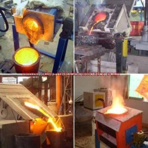
Metal melting furnaces operate at high temperatures and often require continuous cooling of the induction coil and electrical components.
The cooling circuit must be designed for the actual furnace and power supply.
Special attention is required because water entering molten metal can create a serious explosion hazard.
A cooling-system fault must be addressed using the furnace manufacturer’s approved safety procedures.
4. Induction Brazing Equipment Cooling
Induction brazing systems use electromagnetic heating to join copper, brass, steel, and other suitable metals.
Water-cooled coils and power electronics may require a controlled cooling-water circuit.
A properly selected chiller supports stable operation during repeated brazing cycles.
5. High-Frequency Welding Equipment
High-frequency welding systems may require cooling for power electronics, transformers, and welding components.
The chiller should be selected according to the actual equipment heat rejection and required water conditions.
6. CNC Machine Tools and EDM Equipment
Industrial chillers are used to remove heat from machine tools, electrical discharge machining equipment, and temperature-sensitive manufacturing systems.
Stable cooling temperatures can help reduce undesirable thermal variation in suitable precision applications.
7. Injection Molding Machines
Plastic injection molding equipment may require controlled cooling for molds, hydraulic systems, and related process equipment.
The required cooling capacity depends on the process, material throughput, mold temperature, and production cycle.
8. Chemical and Industrial Process Cooling
Air-cooled chillers can support suitable industrial process cooling applications, including chemical equipment, manufacturing systems, and other processes requiring chilled water.
Liquid compatibility, contamination control, and temperature requirements must be evaluated before selecting the cooling circuit.
Industrial Applications Comparison
| Application | Component Requiring Cooling | Engineering Priority |
|---|---|---|
| Induction Heating Generator | Power Electronics and Associated Circuits | Temperature and Flow Stability |
| Induction Hardening | Generator and Induction Coil | Continuous Cooling |
| Induction Melting | Furnace Coil and Electrical Components | Cooling Reliability and Safety |
| Induction Brazing | Induction Coil and Power Supply | Repeatable Cooling Performance |
| High-Frequency Welding | Welding Power Electronics | Cooling Capacity |
| CNC Machine Tools | Spindle or Process Components | Temperature Stability |
| Injection Molding | Mold and Process Equipment | Controlled Cooling Temperature |
| Industrial Process Equipment | Process Heat Exchangers | Thermal Load and Liquid Compatibility |
Working Principle
An air-cooled industrial water chiller uses a refrigeration cycle to remove heat from circulating process water.
The system contains a compressor, condenser, expansion device, and evaporator.
The process water circulates through the evaporator or chilled-water tank and transfers heat to the refrigeration system.
How an Air-Cooled Water Chiller Works
- Warm process water returns from the industrial equipment.
- The water transfers heat to refrigerant through the evaporator.
- The compressor raises the refrigerant pressure and temperature.
- The air-cooled condenser rejects heat to ambient air.
- The expansion valve reduces refrigerant pressure.
- The refrigerant returns to the evaporator to absorb additional heat.
- The circulating pump supplies cooled water to the industrial equipment.
Figure 1. Industrial Water Chiller Working Principle
        INDUSTRIAL EQUIPMENT
        Induction Heating System
                  |
                  |
            WARM RETURN WATER
                  |
                  v
       +--------------------+
       | WATER TANK         |
       | AND EVAPORATOR     |
       +--------------------+
                  |
                  v
       +--------------------+
       | CIRCULATION PUMP   |
       +--------------------+
                  |
                  v
            COOLED WATER
                  |
                  v
        INDUSTRIAL EQUIPMENT


REFRIGERATION CIRCUIT

       +--------------------+
       | COMPRESSOR         |
       +--------------------+
                  |
                  v
       +--------------------+
       | AIR-COOLED         |
       | CONDENSER          |
       +--------------------+
                  |
             HEAT TO AIR
                  |
                  v
       +--------------------+
       | EXPANSION VALVE    |
       +--------------------+
                  |
                  v
       +--------------------+
       | EVAPORATOR         |
       +--------------------+
                  |
                  v
             COMPRESSOR

Important Cooling Terminology
| Term | Meaning |
|---|---|
| Cooling Capacity | Rate of Heat Removal from the Process Water |
| Input Power | Electrical Power Consumed by the Chiller |
| Cooling Water Flow | Volume of Liquid Circulated per Unit Time |
| Supply Temperature | Water Temperature Leaving the Chiller |
| Return Temperature | Water Temperature Returning from the Equipment |
| Temperature Difference | Return Temperature Minus Supply Temperature |
| COP | Cooling Capacity Divided by Electrical Input Power |
| Pump Head | Pressure Energy Available to Overcome Hydraulic Resistance |
Technical Specifications
The following specifications are based on the published AC-Series product information.
Nominal cooling capacity is measured under stated test conditions and should not be treated as guaranteed capacity at every operating temperature.
AC-Series Cooling Capacity and Electrical Parameters
| Model | Cooling Capacity (kW) | Input Power (kW) | Nominal Flow (m³/h) |
|---|---|---|---|
| AC-12 | 29.75 | 11.82 | 5.12 |
| AC-15 | 41.8 | 16.42 | 7.20 |
| AC-20(D) | 55.3 | 20.41 | 9.52 |
| AC-25(D) | 59.5 | 23.45 | 10.25 |
| AC-30(D) | 83.6 | 32.75 | 14.39 |
| AC-40(D) | 109.6 | 40.35 | 18.87 |
Water Circuit and Pump Specifications
| Model | Water Tank (L) | Pump Power (kW) | Published Pump Lift (m) | Pipe Size |
|---|---|---|---|---|
| AC-12 | 200 | 1.5 | 20 | 2 inch |
| AC-15 | 270 | 1.5 | 20 | 2 inch |
| AC-20(D) | 350 | 2.25 | 20 | 2 inch |
| AC-25(D) | 350 | 2.25 | 20 | 2-1/2 inch |
| AC-30(D) | 420 | 3.75 | 22 | 2-1/2 inch |
| AC-40(D) | 580 | 3.75 | 22 | 3 inch |
Engineering Note: The published pump lift is not a complete pump performance curve. Actual available head at the required flow must be confirmed before installation.
Cabinet Dimensions and Weight
| Model | Length (mm) | Width (mm) | Height (mm) | Weight (kg) |
|---|---|---|---|---|
| AC-12 | 1530 | 780 | 1430 | 530 |
| AC-15 | 1850 | 990 | 1680 | 750 |
| AC-20(D) | 2000 | 1130 | 1720 | 835 |
| AC-25(D) | 2000 | 1130 | 1924 | 920 |
| AC-30(D) | 2000 | 1480 | 1800 | 1150 |
| AC-40(D) | 2000 | 1560 | 1800 | 1350 |
General Technical Specifications
| Parameter | Published Specification | Engineering Notes |
|---|---|---|
| Series | AC-Series | Air-Cooled Industrial Water Chiller |
| Electrical Supply | 3-Phase, 380V, 50Hz | Confirm Requirements for Other Markets |
| Compressor | Hermetic Scroll | Confirm Brand and Current Configuration |
| Condenser | Finned Copper Tube and Fan | Air-Cooled |
| Expansion Control | Thermostatic Expansion Valve | Published Configuration |
| Evaporator | Water Tank with Coil | Published Configuration |
| Refrigerant in Original Table | R22 | Current Legal and Commercial Configuration Must Be Confirmed |
| Chilled Water Temperature Range | 5–35°C | Published Operating Range |
| Water Temperature Difference | 3–8°C | Published Operating Range |
| Recommended Ambient Condition | 35°C or Below | Published Recommendation |
| Temperature Control Accuracy | ±1°C | Published Feature |
| Warranty | One Year | Published Information; Confirm Current Terms |
Nominal Cooling Capacity Test Conditions
| Test Parameter | Published Condition |
|---|---|
| Chilled Water Inlet | 12°C |
| Chilled Water Outlet | 7°C |
| Cooling Air Inlet | 30°C |
| Cooling Air Outlet | 35°C |
| Chilled Water Temperature Difference | 5°C |
Important: The published nominal cooling capacities apply to these stated test conditions.
For induction heating equipment requiring water temperatures around 20–30°C, the actual chiller capacity must be confirmed at the selected operating conditions.
Cooling capacity also changes with ambient temperature, refrigerant selection, compressor performance, and condenser operating conditions.
AC-Series Model Comparison
Cooling Capacity vs. Electrical Input Power
Cooling capacity and electrical input power are two different parameters.
Cooling capacity represents how much heat the chiller can remove from circulating water.
Input power represents the electrical power consumed by the chiller.
For example, the AC-40(D) has a published nominal cooling capacity of 109.6kW and input power of 40.35kW.
This does not mean that the machine produces cooling energy without consuming electricity.
It transfers heat from the water to the environment through a refrigeration cycle.
Calculated Nominal Cooling COP
The cooling coefficient of performance is:
COP = Cooling Capacity / Electrical Input Power
| Model | Cooling Capacity | Input Power | Calculated Nominal COP |
|---|---|---|---|
| AC-12 | 29.75kW | 11.82kW | 2.52 |
| AC-15 | 41.8kW | 16.42kW | 2.55 |
| AC-20(D) | 55.3kW | 20.41kW | 2.71 |
| AC-25(D) | 59.5kW | 23.45kW | 2.54 |
| AC-30(D) | 83.6kW | 32.75kW | 2.55 |
| AC-40(D) | 109.6kW | 40.35kW | 2.72 |
The COP values are calculated from the published nominal cooling capacities and published chiller input powers.
They are not independently measured test results.
Figure 2. Nominal Cooling Capacity Comparison
AC-SERIES NOMINAL COOLING CAPACITY

AC-12     ██████                  29.75kW

AC-15     ████████                41.8kW

AC-20(D)  ███████████             55.3kW

AC-25(D)  ████████████            59.5kW

AC-30(D)  █████████████████       83.6kW

AC-40(D)  ██████████████████████  109.6kW

Nominal conditions:
Water 12°C inlet / 7°C outlet
Air 30°C inlet
Engineering Selection Guide
The correct industrial water chiller should be selected according to the actual cooling heat load rather than the electrical rating of the connected induction heating machine.
For example, a 100kW induction heating generator does not automatically require a 100kW water chiller.
The chiller must remove heat generated by electrical losses, coil losses, and other components connected to its water circuit.
1. Calculate Required Cooling Capacity
For water, the cooling heat load can be estimated using:
Q = 1.163 × F × ΔT
Where:
- Q = Cooling heat load, kW
- F = Water flow, m³/h
- ΔT = Water temperature difference, °C
This equation assumes water near ordinary industrial cooling temperatures.
For other liquids or glycol mixtures, the actual density and specific heat capacity must be used.
2. Cooling Load Calculation Examples
| Water Flow | Temperature Rise | Calculated Cooling Load |
|---|---|---|
| 3m³/h | 5°C | 17.4kW |
| 5m³/h | 5°C | 29.1kW |
| 8m³/h | 5°C | 46.5kW |
| 10m³/h | 5°C | 58.2kW |
| 12m³/h | 5°C | 69.8kW |
| 15m³/h | 5°C | 87.2kW |
| 18m³/h | 5°C | 104.7kW |
These values represent theoretical water-side heat loads calculated from flow and temperature rise.
They are not chiller performance test results.
3. Recommended Model Selection
For preliminary sizing, a design allowance may be added to the expected steady-state cooling load.
The following examples use a 20% allowance.
| Estimated Cooling Load | Load with 20% Allowance | Preliminary Model | Nominal Capacity |
|---|---|---|---|
| 20kW | 24kW | AC-12 | 29.75kW |
| 30kW | 36kW | AC-15 | 41.8kW |
| 45kW | 54kW | AC-20(D) | 55.3kW |
| 49kW | 58.8kW | AC-25(D) | 59.5kW |
| 65kW | 78kW | AC-30(D) | 83.6kW |
| 90kW | 108kW | AC-40(D) | 109.6kW |
Important: The selected models are preliminary examples based on published nominal capacities.
The final chiller must be checked against actual ambient temperature, required chilled-water temperature, operating duty, pump performance, and refrigerant configuration.
A 20% allowance is an illustrative engineering assumption, not a universal requirement.
4. Example: Selecting a Chiller for an Induction Heating System
Assume an induction heating installation has the following measured cooling-water conditions:
| Parameter | Assumed Value |
|---|---|
| Cooling Water Flow | 10m³/h |
| Cooling Water Supply Temperature | 25°C |
| Cooling Water Return Temperature | 30°C |
| Temperature Difference | 5°C |
| Design Allowance | 20% |
The estimated cooling heat load is:
Q = 1.163 × 10 × 5
Q = 58.15kW
Including the assumed 20% design allowance:
Required Capacity = 58.15 × 1.20
Required Capacity ≈ 69.8kW
Based on published nominal cooling capacity alone, the AC-30(D) would be the first AC-Series model in the table exceeding this value.
However, the required supply temperature is 25°C rather than the nominal test temperature of 7°C.
The actual capacity at 25°C must therefore be confirmed using the manufacturer’s performance data.
The circulation pump must also provide the required flow against the complete system pressure losses.
5. Cooling Capacity vs. Induction Generator Power
| Induction Equipment Parameter | Engineering Meaning |
|---|---|
| Generator Rated Input Power | Total Electrical Power Drawn by the Generator |
| Useful Heating Power | Power Transferred to the Workpiece |
| Generator Electrical Losses | Part of the Heat Requiring Removal |
| Induction Coil Losses | Heat Generated in Coil Conductors |
| Matching Circuit Losses | Heat Generated in Matching Components |
| Water-Side Cooling Load | Heat Actually Transferred to the Cooling Circuit |
The cooling system should be sized using the heat rejected to water, not simply the generator’s input power rating.
Cooling System Design for Induction Heating Equipment
A suitable induction cooling system must provide sufficient cooling capacity, stable water flow, acceptable water quality, and reliable safety protection.
1. Typical Closed-Loop Cooling Arrangement
       AIR-COOLED CHILLER
     +--------------------+
     | COMPRESSOR         |
     | CONDENSER          |
     | EVAPORATOR         |
     | WATER TANK         |
     | WATER PUMP         |
     +--------------------+
                |
                |
         COOLED WATER
                |
                v
     +--------------------+
     | INDUCTION          |
     | POWER SUPPLY       |
     +--------------------+
                |
                v
     +--------------------+
     | MATCHING CIRCUIT   |
     | / TRANSFORMER      |
     +--------------------+
                |
                v
     +--------------------+
     | INDUCTION COIL     |
     +--------------------+
                |
                |
         WARM RETURN WATER
                |
                v
        AIR-COOLED CHILLER
The schematic illustrates a functional cooling concept.
The actual system may require separate parallel branches, different flow rates, a secondary heat exchanger, or independent cooling circuits.
2. Single-Circuit vs. Dual-Circuit Cooling
| Configuration | Advantages | Selection Considerations |
|---|---|---|
| Single Closed Cooling Circuit | Simpler Piping and Fewer Components | All Connected Equipment Must Have Compatible Water Requirements |
| Dual Cooling Circuits | Allows Different Water Qualities and Temperature Conditions | Requires Heat Exchanger and Additional Pumping |
| Independent Generator and Coil Cooling | Allows Different Flow and Temperature Settings | Requires More Equipment and Controls |
| Centralized Cooling System | Can Serve Multiple Production Machines | Requires Hydraulic Balancing and Redundancy Planning |
3. Cooling Water Quality
Water quality is important because mineral deposits, corrosion, and contamination can reduce cooling performance or damage sensitive components.
The appropriate water treatment depends on the materials used in the cooling circuit.
| Water Quality Parameter | Engineering Consideration |
|---|---|
| Electrical Conductivity | Must Meet Induction Equipment Requirements |
| Hardness | Excessive Hardness Can Cause Scale |
| pH | Must Be Compatible with Circuit Materials |
| Chloride Concentration | May Influence Corrosion Risk |
| Suspended Particles | Can Block Small Cooling Channels |
| Biological Contamination | Can Contribute to Fouling |
| Corrosion Protection | Must Be Suitable for the Complete Circuit |
Some induction generators require low-conductivity cooling water.
The published AC-Series water tank and evaporator arrangement should not automatically be assumed compatible with deionized-water circuits.
Where necessary, a secondary heat exchanger can separate the chiller water circuit from the induction equipment’s specialized cooling circuit.
4. Avoiding Condensation
Very cold cooling water is not always desirable for induction heating equipment.
If the cooling-water temperature falls below the surrounding air’s dew point, moisture can condense on cold pipes and electrical components.
This may create reliability and electrical insulation problems.
The cooling-water supply temperature should therefore be selected according to the equipment manufacturer’s requirements and the workshop’s temperature and humidity.
Process Workflow
A well-designed industrial chiller installation should include an engineering review, correct installation, commissioning, and regular maintenance.
Industrial Chiller Selection and Installation Process
INDUSTRIAL EQUIPMENT DATA
          |
          v
CALCULATE COOLING LOAD
          |
          v
DEFINE WATER TEMPERATURE
          |
          v
CALCULATE WATER FLOW
          |
          v
CHECK PUMP HEAD
          |
          v
SELECT CHILLER MODEL
          |
          v
VERIFY ACTUAL CAPACITY
          |
          v
INSTALL PIPING
AND ELECTRICAL SUPPLY
          |
          v
CHECK WATER QUALITY
AND FLOW
          |
          v
COMMISSION CHILLER
          |
          v
MEASURE PERFORMANCE
          |
          v
ROUTINE MAINTENANCE
Commissioning Checklist
| Inspection Item | Required Check |
|---|---|
| Electrical Supply | Correct Voltage, Phase and Protection |
| Installation Location | Adequate Ventilation and Service Clearance |
| Cooling Water Piping | Correct Connections and Leak Inspection |
| Water Flow | Meets Equipment Requirements |
| Water Pressure | Within Equipment Limits |
| Water Quality | Compatible with Connected Equipment |
| Temperature Setting | Correct Supply Temperature |
| Protection Functions | Alarms and Interlocks Verified |
| Cooling Performance | Measured Under Operating Load |
| Maintenance Access | Adequate Service Space |
Control System and Automation
The AC-Series uses digital temperature control and includes several equipment protection functions.
The published product information specifies temperature control accuracy of ±1°C.
Actual control accuracy depends on sensor installation, process conditions, controller configuration, and equipment operation.
Control and Safety Features
| Control Function | Purpose |
|---|---|
| Digital Temperature Control | Maintains the Selected Water Temperature |
| Temperature Display | Displays Cooling Water Conditions |
| Fault Code Display | Supports Troubleshooting |
| Compressor Overtemperature Protection | Protects the Compressor |
| Compressor Overcurrent Protection | Protects Electrical Components |
| High-Pressure Protection | Protects Refrigeration Circuit |
| Low-Pressure Protection | Detects Abnormal Refrigeration Conditions |
| Phase Sequence Protection | Protects Three-Phase Equipment |
| Phase-Loss Protection | Detects Missing Electrical Phases |
| Discharge Temperature Protection | Protects Refrigeration Components |
PLC integration, remote communication, automatic backup operation, and additional industrial interlocks should be confirmed according to the customer’s project requirements.
Common Problems and Solutions
Industrial water chiller performance can be affected by ambient temperature, refrigeration conditions, water flow, equipment maintenance, and process load.
| Common Problem | Possible Cause | Recommended Solution |
|---|---|---|
| Water Temperature Too High | Insufficient Cooling Capacity | Measure Actual Cooling Load and Verify Chiller Capacity |
| Insufficient Water Flow | Blocked Filter or Excessive Pressure Loss | Inspect Piping, Filters and Pump Performance |
| Compressor High-Pressure Alarm | Insufficient Condenser Airflow | Inspect Condenser and Ventilation |
| Low Refrigeration Pressure | Possible Refrigeration System Fault | Use Qualified Refrigeration Service Personnel |
| Unstable Water Temperature | Changing Process Load or Control Issue | Review Temperature Settings and Actual Load |
| Frequent Compressor Cycling | Low Load or Control Configuration | Review Load Matching and Control Settings |
| Cooling Water Leakage | Damaged Connections or Components | Stop Unsafe Operation and Repair the Circuit |
| Coil Overheating | Insufficient Flow Through Induction Coil | Verify Coil Cooling Requirements and Branch Flow |
| Water Scaling | Unsuitable Water Quality | Review Water Treatment and Cleaning Procedures |
| Condensation on Components | Cooling Water Below Ambient Dew Point | Review Water Temperature and Humidity Conditions |
| Excessive Electrical Consumption | High Ambient Temperature or Refrigeration Fault | Check Operating Conditions and Equipment Performance |
| Insufficient Pump Pressure | Pump Not Matched to System Resistance | Review Hydraulic Calculations and Pump Curve |
Recommended Troubleshooting Sequence
- Check the chiller alarm code.
- Verify electrical supply conditions.
- Measure cooling-water supply and return temperatures.
- Measure actual circulation flow.
- Check water filters and piping restrictions.
- Inspect condenser airflow and cleanliness.
- Verify the actual process cooling load.
- Review refrigeration-system performance with qualified personnel.
Refrigerant handling and refrigeration circuit repairs must be performed by appropriately qualified technicians.
Advantages
1. Controlled Industrial Cooling
The AC-Series provides refrigeration-based cooling for industrial equipment requiring controlled circulating-water temperatures.
2. Air-Cooled Condenser
The air-cooled condenser rejects heat to the surrounding air without requiring a separate condenser-water cooling tower.
3. Multiple Cooling Capacity Options
Six published models provide nominal cooling capacities from 29.75kW to 109.6kW.
4. Integrated Circulation System
The published AC-Series configurations include water tanks and circulating pumps.
5. Digital Temperature Control
The product information specifies digital temperature control and fault-code indication.
6. Compressor Protection
The system includes protection functions for abnormal compressor and refrigeration conditions.
7. Industrial Application Flexibility
The chillers can be evaluated for induction heating, welding, metalworking, machine tools, and other industrial process cooling applications.
8. Supports Equipment Reliability
When correctly selected, a water chiller helps maintain the required cooling conditions and reduce risks associated with excessive component temperature.
Limitations
The AC-Series industrial water chiller must be selected according to the actual operating conditions.
| Limitation | Engineering Explanation | Recommended Action |
|---|---|---|
| Nominal Capacity Conditions | Rated Capacity Depends on Water and Ambient Temperatures | Request Performance Data at Actual Conditions |
| High Ambient Temperature | Cooling Capacity May Be Reduced | Verify High-Ambient Operation |
| Low Cooling Water Temperature | May Cause Condensation | Check Dew Point and Equipment Requirements |
| Hydraulic Resistance | Published Pump Lift Does Not Define Full Pump Curve | Verify Available Pump Head at Design Flow |
| Water Quality | Some Equipment Requires Special Cooling Water | Verify Water Compatibility |
| Refrigerant Selection | Original Product Table Specifies R22 | Confirm Current Compliant Configuration |
| High Cooling Demand | Largest Published Model Is 109.6kW Nominal | Evaluate Multiple Units or Larger Systems |
| Critical Industrial Processes | Single-Chiller Failure May Stop Production | Consider Redundancy |
Important Refrigerant Compliance Notice
The original AC-Series product table lists R22 refrigerant.
R22 is an ozone-depleting HCFC refrigerant subject to restrictions or prohibitions in many markets.
For new equipment supplied to the European Union or other regulated markets, the refrigerant and complete refrigeration system must comply with the applicable laws.
A compliant alternative refrigerant cannot necessarily be substituted directly into an existing R22 refrigeration circuit.
The compressor, expansion valve, heat exchangers, operating pressures, electrical components, and safety requirements may need to be redesigned or revalidated.
Customers should request confirmation of the current refrigerant configuration and applicable compliance documentation before ordering.
Why Choose HLQ Induction Equipment?
HLQ Induction Equipment Co., Ltd. supplies induction heating equipment and associated industrial systems for metalworking applications.
The AC-Series industrial water chiller range can be evaluated for use with compatible induction heating power supplies, induction hardening machines, induction furnaces, and other industrial equipment.
Proper chiller selection should be based on measured equipment heat rejection, cooling-water temperature, required circulation flow, hydraulic resistance, and operating environment.
For related industrial equipment, explore HLQ’s
industrial induction melting furnaces
and
industrial induction brazing machines.
Information Required for a Technical Quotation
| Customer Requirement | Information to Provide |
|---|---|
| Application | Induction Heating, Melting, Hardening or Other |
| Equipment Power | Electrical Input Power, kW |
| Cooling Heat Load | kW |
| Required Supply Temperature | °C |
| Expected Return Temperature | °C |
| Required Water Flow | m³/h or L/min |
| System Pressure Loss | kPa or bar |
| Ambient Temperature | Maximum Expected °C |
| Electrical Supply | Voltage, Frequency and Phase |
| Water Quality | Required Conductivity, Hardness and Other Limits |
| Installation | Indoor or Outdoor |
| Refrigerant Requirements | Country and Applicable Regulations |
| Continuous Operation | Operating Hours per Day |
Providing complete technical information helps ensure that the selected chiller matches the intended cooling application.
Frequently Asked Questions
FAQ 1: What is an industrial water chiller?
An industrial water chiller is a refrigeration system that removes heat from circulating water used to cool manufacturing equipment.
The HLQ AC-Series uses an air-cooled condenser, scroll compressor, evaporator, circulation pump, and water tank.
Its published nominal cooling capacities range from 29.75kW to 109.6kW.
Typical applications include induction heating machines, metal melting furnaces, induction hardening systems, welding equipment, and industrial process cooling.
FAQ 2: What size water chiller is required for an induction heating machine?
The correct chiller capacity depends on the actual heat rejected to the cooling water rather than the induction generator’s electrical input power alone.
For example, a 100kW induction generator does not automatically require a 100kW chiller.
The required cooling capacity should be calculated from the generator’s heat losses, induction coil losses, and other connected water-cooled components.
The water flow, supply temperature, return temperature, and ambient conditions must also be considered.
FAQ 3: How do I calculate cooling capacity from water flow and temperature difference?
For water, cooling capacity can be estimated using:
Cooling Capacity (kW) = 1.163 × Flow (m³/h) × Temperature Difference (°C)
For example, at 10m³/h and a 5°C temperature difference:
Q = 1.163 × 10 × 5 = 58.15kW
This represents the approximate heat removed from the water.
The selected chiller must provide sufficient cooling capacity under the actual operating conditions.
FAQ 4: What is the difference between cooling capacity and chiller input power?
Cooling capacity is the amount of heat the chiller removes from the process water per unit time.
Input power is the electrical power consumed by the chiller.
For example, the AC-40(D) has a published nominal cooling capacity of 109.6kW and an electrical input power of 40.35kW.
The ratio of cooling capacity to input power is the cooling coefficient of performance.
For this model, the calculated nominal COP is approximately 2.72.
Actual performance depends on operating conditions.
FAQ 5: Can an air-cooled industrial water chiller operate continuously for 24 hours?
An appropriately selected industrial chiller can support continuous production when its cooling capacity, refrigeration system, electrical supply, and operating environment are suitable.
However, the original AC-Series product page does not establish a separate guaranteed 24-hour operating rating for every model.
Continuous operation should therefore be confirmed against the specific equipment configuration.
Regular maintenance, adequate condenser airflow, and appropriate protection functions are important.
FAQ 6: What cooling water temperature is recommended for induction heating equipment?
The correct cooling-water temperature depends on the induction heating power supply, induction coil, connected equipment, and workshop conditions.
The HLQ AC-Series has a published chilled-water operating range of 5–35°C.
However, this range does not mean every temperature is suitable for every induction heating application.
Very low cooling-water temperatures may cause condensation on pipes or electrical components in humid environments.
The final supply-water temperature should follow the induction equipment manufacturer’s requirements.
FAQ 7: Can one industrial chiller cool several induction heating machines?
Yes. A centralized industrial cooling system can serve several induction heating machines if the total cooling capacity and hydraulic design are sufficient.
The total heat load should include all simultaneously operating equipment.
The circulation system must provide the required water flow to each machine.
Parallel branch balancing, flow monitoring, isolation valves, and redundancy should be considered when necessary.
For critical production lines, an independent backup chiller may improve operating reliability.
FAQ 8: How do I select the correct industrial air-cooled water chiller?
Selecting an industrial air-cooled water chiller requires evaluating the cooling heat load, required supply-water temperature, return-water temperature, water flow, system pressure loss, ambient temperature, electrical supply, and cooling-water quality.
The required cooling capacity should be calculated from actual process data, with a suitable design allowance.
The chiller’s published nominal performance must then be corrected or verified for the intended operating conditions.
For the HLQ AC-Series, available published nominal capacities range from 29.75kW to 109.6kW.
The current refrigerant configuration, electrical specifications, and complete cooling requirements should be confirmed before purchasing.
Final Engineering Summary
The HLQ AC-Series industrial air-cooled water chiller provides refrigeration-based cooling for induction heating equipment and other industrial manufacturing systems.
The product range includes six published models with nominal cooling capacities from 29.75kW to 109.6kW.
The correct model should be selected according to actual cooling heat load, supply-water temperature, water flow, ambient conditions, and hydraulic resistance.
For induction heating applications, special attention should be given to water quality, coil cooling requirements, equipment protection, and condensation control.
The refrigerant and complete equipment configuration must also be verified for compliance with the destination market’s applicable regulations.
Manufacturer: HLQ Induction Equipment Co., Ltd.
Product: Industrial Air-Cooled Water Chiller
Series: AC-Series
Models: AC-12 / AC-15 / AC-20(D) / AC-25(D) / AC-30(D) / AC-40(D)
Nominal Cooling Capacity: 29.75–109.6kW
Electrical Supply: Three-Phase 380V, 50Hz
Cooling Method: Air-Cooled Refrigeration
Main Applications: Induction Heating, Induction Hardening, Metal Melting and Industrial Process Cooling