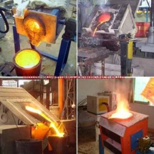
Electric Copper melting Furnace Power With Induction
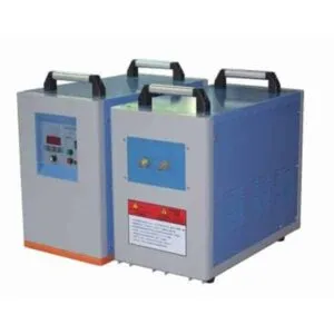
DW-MF-110KW Induction Power Supply for Copper Melting
Quick Answer
The HLQ DW-MF-110KW induction copper melting power supply is a medium-frequency IGBT induction generator designed to provide electromagnetic heating power for compatible electric copper melting furnaces. It has a published maximum oscillation power of 110kW and operates at 1–20kHz. When integrated with a properly designed induction coil, matching circuit, crucible, refractory lining, and cooling system, it can support industrial copper melting, copper scrap recycling, brass and bronze processing, and metal casting applications. The best-fit application is a small-to-medium industrial melting installation whose electrical load has been matched to the generator. Actual melting capacity and throughput must be verified for the complete furnace rather than inferred from generator power alone.
DW-MF-110KW Product Overview
| Product Information | Specification |
|---|---|
| Product | Induction Copper Melting Power Supply |
| Manufacturer | HLQ Induction Equipment Co., Ltd. |
| Model | DW-MF-110KW |
| Published Maximum Oscillation Power | 110kW |
| Operating Frequency | 1–20kHz |
| Input Voltage | 380V, Three-Phase |
| Inverter Technology | IGBT Parallel Inverter |
| Cooling | Water Cooling |
| Main Application | Industrial Induction Heating and Melting |
| Complete Furnace Included? | Must Be Confirmed in the Quotation |
Power Supply vs. Complete Copper Melting Furnace
A critical engineering distinction is that an induction power supply is not the same as a complete induction melting furnace.
The DW-MF-110KW generates electrical power for the induction heating circuit. A functioning copper melting furnace also requires a suitable coil, crucible, mechanical structure, cooling arrangement, and molten metal handling system.
| Component | Function | Supply Consideration |
|---|---|---|
| IGBT Generator | Produces Medium-Frequency Power | Core Product |
| Matching Circuit | Matches Generator to Furnace Load | Configuration-Dependent |
| Induction Coil | Generates Alternating Magnetic Field | Application-Specific |
| Crucible | Contains Metal Charge | Required for Furnace |
| Refractory Lining | Provides Thermal and Structural Protection | Furnace-Dependent |
| Cooling System | Removes Heat from Electrical Components | Required |
| Temperature Monitoring | Measures Melting Temperature | Application-Specific |
| Tilting Mechanism | Supports Molten Metal Pouring | Optional by Furnace Design |

Key Applications
The DW-MF-110KW induction power supply can be integrated into different industrial metal melting systems when the electrical and mechanical components are correctly matched.
1. Copper Scrap Melting and Recycling
Copper recycling facilities use induction melting to recover reusable metal from sorted and prepared copper scrap.
Typical charge materials include copper wire, copper pipes, busbar offcuts, clean copper production returns, and copper ingots.
The main engineering challenges are charge preparation, moisture prevention, furnace capacity, energy consumption, and contamination control.
For complete melting equipment, explore HLQ’s
copper melting induction furnaces for recycling and alloy casting.
2. Copper Ingot Melting
Copper ingots can be heated and melted before casting into copper bars, billets, electrical components, and other industrial products.
The furnace must provide sufficient energy to heat the solid copper to approximately 1084.6°C, complete the melting process, and achieve the specified pouring temperature.
The required melting time depends on ingot dimensions, charge mass, furnace efficiency, and actual electrical input power.
3. Brass Alloy Melting
Induction melting is suitable for many brass alloys when the furnace and process are correctly configured.
Brass contains zinc, which makes excessive temperature and prolonged holding particularly undesirable.
The process requires suitable temperature management, alloy composition control, and fume extraction.
4. Bronze Alloy Melting
Induction melting can be used for tin bronze, aluminum bronze, and other copper-based alloys.
Different bronze grades have different melting ranges, chemical compositions, and refractory compatibility requirements.
The furnace design should therefore be selected according to the specific alloy rather than treating all bronze materials as identical.
5. Copper Foundry Casting
Industrial foundries use molten copper and copper alloys for sand casting, permanent-mold casting, and specialized metal components.
Important process variables include pouring temperature, composition, casting schedule, metal cleanliness, and overall melting productivity.
6. Electrical Copper Component Production
Copper is used in electrical connectors, conductive components, busbars, terminals, and industrial electrical assemblies.
For electrical-grade copper applications, material purity, oxygen content, and conductivity requirements must be considered during process development.
Applications Comparison
| Application | Material | Primary Engineering Requirement | Common Challenge |
|---|---|---|---|
| Copper Scrap Recycling | Prepared Copper Scrap | Efficient Melting | Contamination and Moisture |
| Copper Ingot Casting | Pure Copper | Temperature Control | Oxidation |
| Brass Casting | Copper-Zinc Alloy | Composition Control | Zinc Loss |
| Bronze Casting | Copper-Based Alloys | Alloy Homogeneity | Composition Variation |
| Electrical Copper Production | Specified Copper Grade | Metal Purity | Conductivity and Oxygen Content |
| Industrial Foundries | Copper and Copper Alloys | Repeatable Production | Cycle Time and Metal Yield |
Suitable Materials
Induction heating can be used with electrically conductive materials, but the power supply, crucible, coil, and frequency must be selected according to the metal.
The DW-MF-110KW is primarily discussed here as a potential power source for copper and copper alloy melting.
Melting Temperatures and Material Characteristics
| Material | Approximate Melting Temperature | Typical Application | Engineering Consideration |
|---|---|---|---|
| Pure Copper | 1084.6°C | Copper Casting | High Electrical Conductivity |
| Brass | Alloy-Dependent | Brass Components | Zinc Loss and Fumes |
| Tin Bronze | Alloy-Dependent | Bronze Castings | Composition Control |
| Aluminum Bronze | Alloy-Dependent | Wear-Resistant Castings | Oxidation Control |
| Aluminum | 660°C for Pure Aluminum | Aluminum Casting | Different Thermal Requirements |
| Silver | 961.8°C | Precious Metal Processing | Purity and Crucible Compatibility |
| Steel | Composition-Dependent | Ferrous Melting | Higher Furnace Temperature Requirements |
Engineering Note: Most industrial alloys do not have one exact melting temperature. They generally melt over a solidus-to-liquidus interval.
Copper Charge Preparation
| Charge Material | Required Preparation | Main Risk |
|---|---|---|
| Copper Ingots | Inspect and Keep Dry | Large Pieces and Handling Damage |
| Copper Wire Scrap | Remove Insulation and Contaminants | Coatings and Foreign Materials |
| Copper Tubes | Check for Trapped Liquid | Water Contamination |
| Copper Chips | Approved Cleaning and Drying | Oil, Moisture and Low Bulk Density |
| Mixed Copper Scrap | Sort by Grade | Uncontrolled Alloy Composition |
Working Principle
The DW-MF-110KW uses electromagnetic induction to supply heating energy to a compatible metal melting system.
The generator converts industrial three-phase electricity into medium-frequency alternating electrical power.
This power is supplied to an induction heating circuit, producing a changing magnetic field that generates heat in conductive metal.
How Induction Copper Melting Works
- Industrial three-phase electricity enters the induction power supply.
- The rectifier and inverter circuits convert electrical power.
- Medium-frequency current energizes the induction coil.
- The coil produces an alternating magnetic field.
- Induced electrical currents generate heat in the metal or suitable conductive crucible.
- The metal temperature rises until melting occurs.
- Additional energy provides the required superheat for pouring.
- Molten metal is transferred using an approved pouring system.
Figure 1. Induction Copper Melting System Diagram
THREE-PHASE AC INPUT
         |
         v
+----------------------+
| RECTIFIER / DC LINK  |
+----------------------+
         |
         v
+----------------------+
| IGBT INVERTER        |
| DW-MF-110KW          |
+----------------------+
         |
         v
+----------------------+
| MATCHING CIRCUIT     |
+----------------------+
         |
         v
+----------------------+
| INDUCTION COIL       |
+----------------------+
         |
         v
+----------------------+
| CRUCIBLE / FURNACE   |
+----------------------+
         |
         v
+----------------------+
| MOLTEN COPPER        |
+----------------------+
         |
         v
CASTING / POURING

SUPPORTING SYSTEMS:
- WATER COOLING
- ELECTRICAL PROTECTION
- TEMPERATURE MONITORING
- PROCESS CONTROL
Operating Frequency and Heating Penetration
The frequency of an induction heating system influences electromagnetic penetration and electrical load matching.
For a simplified nonmagnetic conductor, skin depth is proportional to the inverse square root of frequency.
Skin Depth = √[2ρ / (ωμ)]
Where:
- ρ = Electrical resistivity
- ω = Angular frequency
- μ = Magnetic permeability
Because copper resistivity changes with temperature, electromagnetic penetration also changes during the melting process.
| Frequency Consideration | Effect | Engineering Implication |
|---|---|---|
| Lower Frequency | Greater Electromagnetic Penetration | Useful for Larger Cross-Sections |
| Higher Frequency | More Surface-Concentrated Current | May Suit Smaller Loads |
| Changing Copper Temperature | Changes Electrical Resistivity | Load Matching Changes |
| Solid-to-Liquid Transition | Changes Charge Geometry | Heating Characteristics Change |
| Different Crucibles | Change Electromagnetic Coupling | Furnace-Specific Design Required |
The published 1–20kHz range does not mean that every furnace connected to the DW-MF-110KW can operate at any frequency within that range.
The inverter, capacitor network, coil and furnace load must form a compatible electrical system.
Technical Specifications
The following specifications are based on the published DW-MF-110KW equipment information.
Parameters that are not confirmed in the published product data are identified separately.
| Parameter | Specification | Notes |
|---|---|---|
| Product Name | Induction Copper Melting Power Supply | Industrial Medium-Frequency Generator |
| Manufacturer | HLQ Induction Equipment Co., Ltd. | China |
| Model | DW-MF-110KW | Published Product Model |
| Maximum Oscillation Power | 110kW | Continuous Real Output Requires Verification |
| Operating Frequency | 1–20kHz | Depends on Load Matching |
| Input Voltage | 380V ±10% | Three-Phase AC |
| Input Frequency | 50/60Hz | Published Specification |
| Maximum Input Current | 170A | Published Value |
| Inverter Technology | IGBT | Solid-State Power Conversion |
| Inverter Configuration | Parallel Inverter | Published Description |
| Cooling Method | Water Cooling | Generator and Related Components |
| Cooling Water Pressure | >0.3MPa | Published Value |
| Cooling Water Flow | 10L/min | Complete-System Requirement Must Be Confirmed |
| Duty Cycle | 100% at 40°C | Under Specified Operating Conditions |
| Generator Dimensions | 560 × 270 × 470mm | Published Dimensions |
| Transformer Dimensions | 550 × 300 × 420mm | Published Dimensions |
| Generator Weight | 55kg | Published Value |
| Transformer Weight | 75kg | Published Value |
| Connecting Cable | 2m | Published Length |
| Protection Functions | Overvoltage, Overcurrent, Overtemperature, Phase Loss, Water Shortage | Published Features |
| Power Factor | Not Published | Request Tested Value |
| Electrical Efficiency | Not Published | Request Tested Value |
| Maximum Furnace Charge | Not Published | Requires Furnace Design |
| Melting Capacity | Not Published | Requires Engineering Verification |
| Temperature Controller | Application-Dependent | Confirm Actual Configuration |
| Induction Coil | Customized | Matched to Furnace Load |
Electrical Input Calculation
For a three-phase system:
Apparent Power = √3 × Voltage × Current / 1000
Using the published electrical values:
S = 1.732 × 380 × 170 / 1000
S ≈ 111.9kVA
This represents the calculated apparent input power at 380V and 170A.
It is not equivalent to verified real electrical input power or useful furnace heating output.
Real input power depends on power factor, while useful thermal power also depends on electrical conversion efficiency and furnace losses.
The published 110kW maximum oscillation power should therefore be verified against the manufacturer’s electrical test data before final electrical installation.
Electrical Power Definitions
| Parameter | Definition | Engineering Significance |
|---|---|---|
| Apparent Power | kVA | Electrical Supply Sizing |
| Real Input Power | kW | Purchased Electrical Power |
| Oscillation Power | Manufacturer-Defined Rating | Requires Technical Clarification |
| Useful Heating Power | kW Delivered to the Charge | Determines Heating Performance |
| Energy Consumption | kWh | Determines Electrical Operating Cost |
| Specific Energy Consumption | kWh/ton | Used to Compare Melting Performance |
Recommended Model Selection
The correct induction melting power supply should be selected according to the required melting throughput, charge mass, furnace dimensions, and process temperature.
The table below provides an energy-based preliminary power estimate using assumed specific electrical consumption of 350–500kWh per metric ton.
The recommended power values represent average real electrical input requirements before additional installation margin. They are not guaranteed HLQ model ratings.
| Application | Material | Recommended Power | Frequency |
|---|---|---|---|
| 100kg/h Copper Melting | Pure Copper | 35–50kW Average Real Input | Furnace-Specific |
| 200kg/h Copper Melting | Pure Copper | 70–100kW Average Real Input | Furnace-Specific |
| 300kg/h Copper Melting | Pure Copper | 105–150kW Average Real Input | Furnace-Specific |
| 500kg/h Copper Melting | Pure Copper | 175–250kW Average Real Input | Furnace-Specific |
| 1000kg/h Copper Melting | Pure Copper | 350–500kW Average Real Input | Furnace-Specific |
| Brass Melting | Brass Alloy | Calculated from Alloy Requirements | Selected for Furnace Design |
| Bronze Melting | Bronze Alloy | Calculated from Alloy Requirements | Selected for Furnace Design |
Important: These are preliminary thermal-energy calculations, not verified furnace production capacities.
Actual generator selection must account for real output capability, thermal efficiency, electrical matching, cold-start losses, refractory heating, and production downtime.
When Is the DW-MF-110KW Worth Considering?
| Application | Preliminary Assessment | Required Verification |
|---|---|---|
| Small Copper Melting Furnace | Potentially Suitable | Crucible Capacity and Coil Matching |
| Intermittent Copper Casting | Potentially Suitable | Batch Energy and Melting Time |
| Small Brass Furnace | Potentially Suitable | Alloy and Temperature Requirements |
| Continuous High-Output Melting | Requires Further Evaluation | Real Power and Hourly Throughput |
| Large Furnace Charge | Not Confirmed | Furnace Geometry and Frequency Matching |
| Turnkey Melting System | Additional Equipment Required | Complete Scope of Supply |
Customers requiring a complete furnace rather than a separate generator can review HLQ’s
industrial copper induction melting furnace systems.
Process Workflow
A reliable induction melting process requires consistent charge preparation, electrical heating control, furnace inspection, and safe molten metal handling.
Figure 2. Copper Melting Process Flow
COPPER CHARGE PREPARATION
           |
           v
MATERIAL INSPECTION
           |
           v
FURNACE LINING CHECK
           |
           v
COOLING SYSTEM CHECK
           |
           v
CONTROLLED CHARGING
           |
           v
INDUCTION HEATING
           |
           v
COMPLETE MELTING
           |
           v
TEMPERATURE MEASUREMENT
           |
           v
ALLOY / MELT QUALITY CHECK
           |
           v
SAFE POURING
           |
           v
CASTING / SOLIDIFICATION
           |
           v
PRODUCTION DATA RECORDING
Process Monitoring Requirements
| Process Stage | Parameter | Engineering Check |
|---|---|---|
| Charge Preparation | Material Condition | Dryness and Cleanliness |
| Furnace Inspection | Crucible and Lining | Wear, Cracks and Damage |
| Cooling Inspection | Water Flow and Pressure | Meets Equipment Requirements |
| Charging | Charge Mass | Within Approved Furnace Capacity |
| Heating | Electrical Power | Stable Operating Conditions |
| Melting | Temperature | Appropriate Measurement |
| Alloy Adjustment | Composition | Material Specification |
| Pouring | Molten Metal Handling | Approved Safety Procedure |
| Maintenance | Equipment Condition | Inspection Records |
Coil and Fixture Design
The induction coil is one of the most important components in the complete melting system.
Coil design influences electrical matching, magnetic coupling, cooling requirements, and heating performance.
1. Induction Coil Geometry
A coreless induction melting furnace typically uses a water-cooled copper induction coil surrounding the melting chamber.
Important design parameters include:
- Coil inside diameter
- Coil height
- Number of turns
- Turn spacing
- Copper conductor dimensions
- Cooling-water flow
- Electrical insulation
- Magnetic coupling
- Electrical matching
2. Crucible and Furnace Lining Selection
The crucible must be suitable for the molten metal temperature, alloy chemistry, and electromagnetic heating arrangement.
The electrical characteristics of the crucible can affect whether heating occurs primarily in the metal charge or in the crucible itself.
The refractory lining must also withstand thermal cycling, chemical exposure, and mechanical loading.
Coil and Crucible Design Table
| Design Parameter | Engineering Requirement | Possible Problem |
|---|---|---|
| Coil Diameter | Matched to Furnace Geometry | Poor Coupling |
| Number of Turns | Matched to Resonant Circuit | Electrical Mismatch |
| Coil Height | Suitable Heating Distribution | Uneven Melting |
| Conductor Size | Suitable Current and Cooling | Coil Overheating |
| Coil Insulation | Suitable Electrical Protection | Electrical Fault |
| Crucible Material | Compatible with Metal and Furnace | Contamination or Failure |
| Refractory Lining | Suitable Thermal and Chemical Resistance | Premature Wear |
| Cooling Water | Correct Flow and Quality | Component Overheating |
Figure 3. Simplified Induction Furnace Cross-Section
      FURNACE OPENING
    ____________________
   /                    \
  |     COPPER CHARGE    |
  |                      |
  |----------------------|
  |                      |
  |   CRUCIBLE / LINING  |
  |                      |
  |======================|
  |   INDUCTION COIL     |
  |======================|
  |                      |
  |   FURNACE SUPPORT    |
  |______________________|

        COIL LEADS
            |
            v
      MATCHING CIRCUIT
            |
            v
       IGBT GENERATOR
3. Cooling System Design
The DW-MF-110KW published cooling specification indicates water pressure above 0.3MPa and flow of 10L/min.
This value must be checked to determine whether it covers the generator alone or the complete melting installation.
The furnace induction coil and other water-cooled components may require additional flow.
Cooling Heat Removal Calculation
The approximate cooling heat removal for water can be calculated using:
Cooling Power (kW) ≈ 0.0697 × Flow (L/min) × Temperature Rise (°C)
For example, at 10L/min and a cooling-water temperature rise of 10°C:
Cooling Power ≈ 0.0697 × 10 × 10 = 6.97kW
This illustrates why cooling flow must be calculated from total heat rejection rather than the generator’s rated heating power alone.
| Cooling Parameter | Engineering Requirement |
|---|---|
| Cooling Flow | Based on Component Heat Rejection |
| Cooling Pressure | Within Manufacturer’s Requirements |
| Water Temperature | Within Specified Operating Limits |
| Water Quality | Controlled According to Equipment Requirements |
| Flow Protection | Required |
| Leak Protection | Required by Risk Assessment |
| Emergency Procedure | Approved System-Level Safety Design |
Safety Warning: Water entering molten metal can cause violent metal ejection or explosions. Cooling leaks and wet charge materials require immediate attention under approved safety procedures.
Control System and Automation
An industrial induction melting system should provide suitable electrical control, temperature monitoring, equipment protection, and process supervision.
The DW-MF-110KW published specifications identify electrical and cooling protection functions.
Additional functions such as PLC automation, temperature feedback, and remote communication must be confirmed for the selected configuration.
Recommended Control Functions
| Control Function | Purpose | Configuration Status |
|---|---|---|
| Power Control | Adjust Heating Input | Confirm Actual Control Range |
| Current Monitoring | Electrical Supervision | Confirm Instrumentation |
| Frequency Monitoring | Check Operating Conditions | Confirm Availability |
| Temperature Monitoring | Measure Molten Metal Temperature | Application-Specific |
| Overcurrent Protection | Protect Power Electronics | Published Feature |
| Overvoltage Protection | Protect Electrical Equipment | Published Feature |
| Overtemperature Protection | Prevent Equipment Overheating | Published Feature |
| Cooling Protection | Detect Cooling Faults | Published Feature |
| Emergency Stop | System Safety | Application-Specific Safety Design |
| PLC Integration | Production Automation | Confirm Availability |
| Data Logging | Record Production Performance | Optional |
| Remote Communication | External Control Integration | Confirm Interface |
Recommended Production Data
| Parameter | Unit | Engineering Purpose |
|---|---|---|
| Charge Weight | kg | Batch Capacity |
| Electrical Energy | kWh | Energy Consumption |
| Average Input Power | kW | Power Utilization |
| Melting Time | min | Production Efficiency |
| Pouring Temperature | °C | Metal Quality |
| Cooling Flow | L/min | Cooling Performance |
| Metal Yield | % | Production Loss |
| Alarm Records | Events | Maintenance Analysis |
Common Problems and Solutions
Copper induction melting problems may originate from electrical matching, furnace design, cooling performance, charge preparation, or operating procedures.
| Problem | Possible Cause | Recommended Solution |
|---|---|---|
| Slow Copper Melting | Insufficient Actual Power | Measure Real Input Power and Review Furnace Matching |
| High Electricity Consumption | Furnace Heat Loss | Inspect Lining and Measure kWh per Ton |
| Overcurrent Alarm | Electrical Load Mismatch | Follow Manufacturer Diagnostic Procedure |
| Unstable Heating | Changing Load or Incorrect Matching | Review Frequency and Resonant Circuit |
| Coil Overheating | Insufficient Cooling | Verify Water Flow and Electrical Conditions |
| Excessive Copper Oxidation | Overheating or Long Holding Time | Control Temperature and Holding Period |
| Excessive Slag | Dirty Charge | Improve Charge Preparation |
| Crucible Cracking | Thermal Shock or Material Incompatibility | Review Crucible Specification and Procedures |
| Uneven Melting | Poor Coil Coupling or Charge Distribution | Review Furnace and Coil Design |
| Low Production Throughput | Long Handling Time or Low Real Power | Measure Complete Production Cycle |
| Brass Composition Changes | Zinc Loss | Control Temperature and Fume Extraction |
| Cooling Alarm | Low Flow or Cooling Fault | Inspect Cooling System |
| Wet Charge Material | Moisture or Trapped Liquid | Stop Unsafe Charging and Apply Approved Safety Procedures |
Recommended Troubleshooting Sequence
- Confirm safe equipment conditions.
- Review electrical and cooling alarms.
- Measure electrical input power and energy consumption.
- Inspect cooling-water performance.
- Check furnace lining and crucible condition.
- Review coil coupling and electrical matching.
- Check charge preparation and material condition.
- Compare measured melting time with the calculated energy requirement.
Electrical maintenance and troubleshooting must be performed by qualified personnel following the manufacturer’s procedures.
Engineering Selection Guide
The correct induction melting power supply should be selected from a thermal energy balance and the required production rate.
The most important questions are how much copper must be melted and how quickly the process must be completed.
1. Copper Melting Energy Calculation
Pure copper melts at approximately 1084.6°C.
The energy required to produce molten copper includes:
- Sensible heating of solid copper
- Latent heat of fusion
- Superheating to the required pouring temperature
For an illustrative process starting near 20°C and ending near 1150°C, the thermodynamic energy requirement is approximately 190–210kWh per metric ton.
Actual electrical energy consumption is higher because of furnace losses and electrical conversion losses.
2. Electrical Energy Consumption Assumptions
For preliminary planning, the following hypothetical specific electrical consumption values can be used.
| Scenario | Specific Energy | Interpretation |
|---|---|---|
| Lower-Loss Case | 350kWh/ton | Favorable Assumed Performance |
| Reference Case | 420kWh/ton | Illustrative Planning Value |
| Higher-Loss Case | 500kWh/ton | Higher Assumed Energy Consumption |
These figures are planning assumptions, not measured or guaranteed values for the DW-MF-110KW.
3. Copper Melting Energy Comparison
| Copper Charge | 350kWh/ton | 420kWh/ton | 500kWh/ton |
|---|---|---|---|
| 25kg | 8.75kWh | 10.5kWh | 12.5kWh |
| 50kg | 17.5kWh | 21kWh | 25kWh |
| 100kg | 35kWh | 42kWh | 50kWh |
| 150kg | 52.5kWh | 63kWh | 75kWh |
| 200kg | 70kWh | 84kWh | 100kWh |
| 500kg | 175kWh | 210kWh | 250kWh |
Figure 4. Estimated Energy for Melting 100kg Copper
COPPER CHARGE: 100kg

350 kWh/ton
██████████████        35 kWh

420 kWh/ton
█████████████████     42 kWh

500 kWh/ton
████████████████████  50 kWh

Illustrative electrical energy only.
Not verified DW-MF-110KW performance.
4. Required Power Calculation
The average real electrical input power can be estimated using:
P = E / t
Where:
- P = Average real electrical input power, kW
- E = Electrical energy required, kWh
- t = Available energized heating time, hours
For example, a 100kg copper charge at an assumed specific energy consumption of 420kWh/ton requires:
E = 0.1 × 420 = 42kWh
If the target energized heating time is 30 minutes:
P = 42 / 0.5 = 84kW
Therefore, the estimated average real electrical input requirement is 84kW.
This does not establish that the DW-MF-110KW can melt 100kg of copper in exactly 30 minutes. Actual power delivery, furnace capacity, and operating conditions must be verified.
5. Melting Time Comparison
The following values assume 42kWh of total electrical energy for a 100kg copper charge.
| Average Real Input Power | Calculated Energized Heating Time |
|---|---|
| 50kW | 50.4min |
| 60kW | 42.0min |
| 70kW | 36.0min |
| 80kW | 31.5min |
| 90kW | 28.0min |
| 100kW | 25.2min |
These values are mathematical energy estimates. They do not include all charging, holding, alloy adjustment, pouring, and maintenance time.
Figure 5. Melting Time vs. Average Electrical Input Power
100kg COPPER
ASSUMED ENERGY: 42kWh

50kW  ████████████████████ 50.4min
60kW  █████████████████    42.0min
70kW  ██████████████       36.0min
80kW  ████████████         31.5min
90kW  ███████████          28.0min
100kW ██████████           25.2min

Calculated energized heating time only.
Not a verified furnace melting test.
6. Estimated Copper Melting Throughput
For preliminary production calculations:
Throughput (kg/h) = 1000 × Average Real Input Power (kW) / Specific Energy Consumption (kWh/ton)
| Average Real Input Power | 350kWh/ton | 420kWh/ton | 500kWh/ton |
|---|---|---|---|
| 60kW | 171kg/h | 143kg/h | 120kg/h |
| 80kW | 229kg/h | 190kg/h | 160kg/h |
| 100kW | 286kg/h | 238kg/h | 200kg/h |
Important: These are hypothetical energy-based throughput estimates. They do not represent guaranteed production capacities for the DW-MF-110KW.
Actual throughput depends on furnace charge capacity, cold-start losses, holding time, material handling, and production efficiency.
7. Practical Equipment Selection Checklist
| Selection Parameter | Customer Information Required | Engineering Purpose |
|---|---|---|
| Metal Type | Copper, Brass, Bronze or Other | Thermal and Metallurgical Requirements |
| Material Grade | Exact Alloy Specification | Temperature and Composition Control |
| Charge Weight | kg per Batch | Furnace Capacity |
| Production Rate | kg/h | Average Power Selection |
| Initial Temperature | °C | Sensible Heating Calculation |
| Pouring Temperature | °C | Superheat Calculation |
| Melting Time | Minutes per Batch | Required Heating Power |
| Charge Geometry | Wire, Ingot, Scrap or Block | Coil and Furnace Matching |
| Electrical Supply | Voltage, Frequency and Phase | Electrical Compatibility |
| Cooling Conditions | Flow, Pressure and Temperature | Cooling System Design |
| Furnace Configuration | Crucible, Lining and Tilting | Mechanical Design |
| Automation | Manual or Automatic | Control System Selection |
Advantages
1. Direct Electromagnetic Heating
Induction melting generates heat in conductive materials without requiring direct combustion at the furnace.
2. Electronically Controlled Power
IGBT inverter technology provides controlled electrical power conversion for industrial heating applications.
3. Flexible Copper Alloy Processing
An appropriately engineered furnace can be configured for copper, brass, bronze, and compatible metal alloys.
4. Repeatable Melting Operations
Consistent charge preparation, suitable power settings, and process monitoring can improve melting repeatability.
5. Reduced Local Combustion Emissions
Electric induction melting does not require direct fuel combustion at the melting vessel.
Indirect electricity-related emissions and process fumes must still be considered.
6. Customizable Furnace Configuration
Different induction coils, crucibles, refractory systems, and handling equipment can be selected for different production requirements.
7. Production Data Monitoring
Appropriate instrumentation can support measurement of electrical energy consumption, melting time, temperature, and equipment alarms.
8. Industrial Protection Functions
The published DW-MF-110KW equipment information includes multiple electrical and cooling protection functions.
These functions support safe equipment operation but do not replace furnace-specific safety systems.
Limitations
The DW-MF-110KW is not a universal copper melting solution.
Its suitability depends on the furnace and production requirements.
| Limitation | Engineering Explanation | Recommended Action |
|---|---|---|
| Power Supply Only | Complete Furnace Components May Not Be Included | Confirm Scope of Supply |
| Unverified Melting Capacity | Maximum Charge Weight Is Not Published | Determine Furnace Capacity |
| Unverified Melting Rate | Generator Power Does Not Guarantee kg/h | Perform Calculation and Testing |
| Frequency Compatibility | Not Every Furnace Matches 1–20kHz | Electrical Matching Study |
| Cooling Requirements | Complete System May Need Greater Flow | Calculate Heat Rejection |
| Refractory Maintenance | Crucible and Lining Wear | Regular Inspection |
| Alloy Control | Different Alloys Require Different Processes | Material-Specific Procedures |
| Molten Metal Safety | High Temperature and Water-Contact Risks | Engineered Protection |
| Electrical Power Quality | Inverter Operation May Produce Harmonics | Review Electrical Installation |
| Electrical Rating | Input and Oscillation Power Definitions Need Confirmation | Verify Manufacturer Test Data |
When Should a Higher-Power Furnace Be Selected?
A higher-power induction melting system should be evaluated when:
- Required copper throughput exceeds the verified furnace capacity.
- Large batches must be melted within short cycles.
- Continuous production requires higher average power.
- The furnace requires a different operating frequency.
- Significant cold-start or holding losses are expected.
- Future production expansion must be accommodated.
Why Choose HLQ Induction Equipment?
HLQ Induction Equipment Co., Ltd. supplies industrial induction heating equipment and power supplies for metalworking applications.
The company’s product range includes medium-frequency induction generators, induction melting furnaces, induction forging systems, heat-treatment equipment, and customized electromagnetic heating solutions.
For copper melting projects, proper equipment selection should begin with charge weight, material grade, desired pouring temperature, melting time, and required production capacity.
The DW-MF-110KW can be evaluated as a power source for a suitable furnace configuration.
Customers requiring integrated melting and downstream casting equipment may also review HLQ’s
induction melting and continuous copper casting systems.
Technical Information Required for a Quotation
| Customer Requirement | Information to Provide |
|---|---|
| Metal | Copper or Copper Alloy Grade |
| Charge Weight | kg per Batch |
| Production Capacity | kg/h |
| Initial Temperature | °C |
| Target Temperature | °C |
| Melting Time | Minutes per Batch |
| Charge Form | Ingot, Wire, Scrap or Other |
| Electrical Supply | Voltage, Frequency and Phase |
| Cooling System | Available Flow and Temperature |
| Equipment Scope | Power Supply or Complete Furnace |
| Pouring Method | Manual or Mechanized |
| Automation | Required Functions and Interfaces |
Providing complete technical information allows the equipment to be evaluated against the actual manufacturing process.
Frequently Asked Questions
FAQ 1: What is an induction copper melting power supply?
An induction copper melting power supply is an electrical power conversion system that generates alternating current for an induction melting furnace.
The alternating current energizes an induction coil, producing a changing magnetic field that generates heat in conductive metal.
The HLQ DW-MF-110KW is a medium-frequency IGBT generator with a published maximum oscillation power of 110kW and an operating frequency range of 1–20kHz.
A complete melting furnace additionally requires suitable coils, electrical matching, a crucible, cooling equipment, and other supporting components.
FAQ 2: How much electricity is required to melt one ton of copper?
The electrical energy required to melt copper depends on the initial temperature, pouring temperature, furnace efficiency, and operating conditions.
The theoretical thermodynamic requirement for heating pure copper from approximately 20°C to 1150°C is roughly 190–210kWh per metric ton.
Actual electrical consumption is higher because of furnace losses and electrical conversion losses.
For preliminary sensitivity calculations, assumed values of 350–500kWh per metric ton may be used.
These values are not guaranteed performance specifications for the DW-MF-110KW.
FAQ 3: Can a 110kW induction power supply melt 100kg of copper?
A 110kW-class induction generator may be suitable for a furnace designed to melt 100kg of copper.
However, suitability depends on the crucible, induction coil, electrical matching, real available power, and thermal efficiency.
At an assumed electrical consumption of 420kWh per metric ton, melting 100kg of copper would require approximately 42kWh.
At a measured average real electrical input of 80kW, the calculated energized heating time would be approximately 31.5 minutes.
This is a hypothetical calculation rather than a verified DW-MF-110KW melting test.
FAQ 4: What frequency is best for induction copper melting?
The best induction melting frequency depends on the copper charge size, electrical conductivity, furnace dimensions, induction coil, and matching circuit.
The DW-MF-110KW has a published frequency range of 1–20kHz.
Lower frequencies generally provide greater electromagnetic penetration, while higher frequencies produce more surface-concentrated currents.
The actual operating frequency must be selected for the complete induction melting circuit.
FAQ 5: What type of crucible is suitable for induction copper melting?
Crucible selection depends on the furnace configuration, copper grade, operating temperature, and chemical compatibility.
Graphite and ceramic-based crucible systems are used in different induction melting applications.
A conductive crucible may absorb induction power directly, while a nonconductive refractory system may allow more direct coupling to the metal.
The crucible and induction coil must therefore be designed as a compatible system.
FAQ 6: Can the same induction melting system process copper, brass, and bronze?
A properly configured induction melting system can potentially process copper, brass, and bronze.
However, these materials have different melting characteristics and metallurgical requirements.
Brass melting requires attention to zinc loss and fume extraction.
Bronze melting requires appropriate alloy composition and temperature control.
The crucible, refractory lining, operating frequency, and process procedure must be checked for each material.
FAQ 7: What cooling system is required for a 110kW induction melting power supply?
The DW-MF-110KW uses water cooling.
The published cooling-water specification is pressure above 0.3MPa and flow of 10L/min.
However, the complete furnace may require additional cooling capacity for the induction coil, matching components, and other equipment.
The final cooling system must be selected according to total heat rejection, cooling-water quality, temperature limits, and manufacturer requirements.
Appropriate cooling monitoring and protection are essential.
FAQ 8: How do I select the correct induction copper melting furnace?
Selecting an induction copper melting furnace requires evaluating the metal grade, charge weight, pouring temperature, desired melting time, production capacity, and available electrical supply.
The average electrical power requirement can be estimated from the required throughput and assumed specific energy consumption.
Operating frequency must be matched to the coil, furnace geometry, resonant circuit, and metal charge.
Buyers should also confirm the crucible, refractory lining, cooling equipment, temperature monitoring, safety protection, and pouring arrangement.
For the DW-MF-110KW, actual melting capacity and performance must be verified using the complete furnace configuration.
Final Engineering Summary
The HLQ DW-MF-110KW induction copper melting power supply is an industrial medium-frequency IGBT generator with a published maximum oscillation power of 110kW and an operating frequency range of 1–20kHz.
It can be evaluated as a power source for compatible copper and copper alloy melting furnaces.
Actual melting capacity, production throughput, and electrical consumption depend on the complete furnace design and operating conditions.
Reliable equipment selection requires verification of real electrical power, induction coil matching, crucible design, cooling performance, and production requirements.
Manufacturer: HLQ Induction Equipment Co., Ltd.
Model: DW-MF-110KW
Maximum Oscillation Power: 110kW
Operating Frequency: 1–20kHz
Electrical Input: Three-Phase 380V
Technology: IGBT Medium Frequency Induction Heating
Main Applications: Copper Melting, Copper Alloy Melting and Industrial Metal Processing