
Continuous Induction Annealing for Wire & Cable with Induction Heating | Engineering Guide
Table of Contents
- Quick Answer
- Application Background
- Why Use Induction Heating for This Application?
- Suitable Materials and Workpieces
- Working Principle
- Key Technical Parameters
- Engineering Selection Guide
- Process Workflow
- Case Study / Typical Application
- Common Problems and Solutions
- FAQ
- Conclusion
Quick Answer
Continuous induction annealing for wire and cable is an inline heat treatment process that uses electromagnetic induction to soften cold-drawn wire, reduce work hardening, restore ductility, improve conductivity stability and prepare conductors for further drawing, stranding, insulation extrusion or forming. It is suitable for copper wire, aluminum wire, copper alloy wire, stainless steel wire, carbon steel wire, resistance wire and special alloy conductors. Induction heating is suitable because it provides fast, controllable, localized and continuous heating that can be synchronized with wire drawing or cable production lines. The recommended equipment is a continuous induction annealing system with induction power supply, multi-turn or tunnel-type coil, closed-loop cooling, pyrometer or contact temperature monitoring, wire tension control and PLC line-speed synchronization.
Application Background
Wire and cable manufacturing usually involves repeated drawing, rolling, shaping or stranding operations. During cold drawing, the wire diameter is reduced by passing the material through dies. This improves dimensional accuracy and surface finish, but it also increases hardness, tensile strength and internal stress while reducing elongation. This phenomenon is called work hardening. If the work-hardened wire is not annealed properly, it may break during further drawing, fail during bending, crack during forming or show unstable electrical and mechanical performance.
Continuous annealing is used to recover ductility and improve process stability. In a modern wire and cable plant, annealing is often required after drawing copper conductors, aluminum conductors, stainless steel wires or special alloy wires. Traditional annealing methods include resistance annealing, gas furnace annealing, muffle furnace annealing and batch furnace annealing. These methods can work, but they may have limitations in line speed control, energy efficiency, floor space, oxidation control, temperature uniformity and startup response.
Continuous induction annealing is increasingly used because it can be installed directly into a wire drawing line or cable production line. It heats the moving wire rapidly and accurately without needing a large furnace chamber. Induction equipment for wire and cable processing is commonly used for annealing, stress relieving, coating preparation and other inline thermal processes; equipment suppliers describe these systems as suitable for continuous production lines because the induction system can be matched to mill speed for uninterrupted processing.
For copper wire used in electrical applications, annealing is especially important because cold drawing changes both mechanical behavior and electrical performance. Copper is valued for high electrical conductivity, but excessive work hardening can reduce flexibility and create handling problems during winding, stranding and cable assembly. For this reason, buyers search for continuous induction annealing when they need higher line speed, better wire softness, lower breakage rate, smaller equipment footprint and better process control.
Industry Problems Before Annealing
| Problem in Wire Production | Typical Cause | Result | Annealing Objective |
|---|---|---|---|
| Wire becomes too hard | Cold drawing and plastic deformation | Poor flexibility and high breakage risk | Restore ductility and reduce hardness |
| Wire breaks during drawing | Excessive work hardening or uneven structure | Line stoppage and material loss | Stabilize mechanical properties |
| Unstable elongation | Inconsistent annealing temperature | Quality variation in cable production | Improve temperature repeatability |
| Oxidized conductor surface | Long high-temperature exposure in air | Poor surface quality and extra cleaning | Shorten heating time and add protection if needed |
| Large annealing furnace footprint | Long residence time in conventional furnace | High floor space and slow response | Use compact inline induction heating |
Why Use Induction Heating for This Application?
Induction heating is well suited for continuous annealing wire and cable annealing because the workpiece is long, narrow, conductive and moving continuously. The induction coil can be installed around the wire path, and the wire can be heated as it passes through the magnetic field. The heating power is adjusted according to wire size, material, line speed and target annealing temperature.
Compared with traditional resistance or furnace heating, induction heating has several practical advantages. It has fast thermal response, compact layout, easy start-stop control, high automation compatibility and good integration with drawing machines, take-up systems and extrusion lines. Industry application examples show continuous copper wire annealing at a line speed of around 15 m/min using an induction heating system, demonstrating the suitability of induction for moving conductor applications.
| Factor | Continuous Induction Annealing | Traditional Furnace Annealing | Engineering Benefit |
|---|---|---|---|
| Heating speed | Very fast, usually seconds | Slower, often minutes or longer | Higher line speed and shorter process length |
| Process layout | Compact inline coil system | Long furnace or batch furnace | Saves factory space |
| Temperature control | Power can follow line speed quickly | High thermal inertia | Better response during speed changes |
| Energy use | Energy is focused on the wire | Furnace chamber and atmosphere are also heated | Lower unnecessary heat loss |
| Automation | Easy PLC integration | Possible but slower response | Better synchronization with drawing line |
| Surface oxidation | Short exposure; protective gas can be added | Long exposure may increase oxidation | Cleaner conductor surface |
Key Benefits for Wire & Cable Manufacturers
| Benefit | Meaning in Production | Buyer Value |
|---|---|---|
| Inline production | Annealing can be synchronized with drawing or take-up speed | Reduces handling and intermediate storage |
| Fast startup | Induction system reaches operating condition quickly | Less warm-up time than large furnaces |
| Accurate energy control | Power can be adjusted according to speed and wire diameter | Stable elongation and tensile strength |
| Compact footprint | Coil and power system require less production space | Easy retrofit into existing lines |
| Clean heating | No open flame around the wire | Improved workshop environment |
| Flexible process | Recipes can be stored for different wire sizes | Faster product changeover |
Suitable Materials and Workpieces
Continuous induction annealing can be applied to many conductive wire materials. However, the heating behavior differs strongly between ferrous and non-ferrous metals. Steel wire is magnetic below its Curie temperature and usually couples well with induction heating. Copper and aluminum are non-magnetic but highly conductive, so they require correct coil design, higher current density and proper frequency selection. Induction heating has been used for both ferrous and non-ferrous wire products for annealing, stress relieving, coating preparation and other inline processes.
| Material | Size | Suitability | Notes |
|---|---|---|---|
| Copper wire | 0.2–8 mm round wire; rectangular conductor possible | Very suitable | Used for electrical wire, motor wire, magnet wire and cable conductor annealing. |
| Oxygen-free copper wire | Fine to medium conductor sizes | Very suitable | Requires good temperature control to protect conductivity and surface quality. |
| Aluminum wire | 0.5–12 mm depending on line | Suitable | Lower density and high conductivity require careful power and speed matching. |
| Copper alloy wire | Fine, round, flat or shaped wire | Suitable | Annealing temperature depends on alloy composition and required mechanical properties. |
| Carbon steel wire | 0.5–16 mm or larger | Very suitable | Magnetic coupling improves heating efficiency; used for stress relieving and softening. |
| Stainless steel wire | 0.3–10 mm typical | Suitable | Often requires controlled atmosphere to reduce oxidation and discoloration. |
| Nickel alloy wire | Fine and precision wire | Suitable | Used for special alloy, resistance wire and precision applications. |
| Flat wire / rectangular wire | Customized width and thickness | Suitable with custom coil | Requires coil field matching for edge and center temperature uniformity. |
Typical Annealing Objectives by Material
| Material Group | Main Annealing Purpose | Typical Quality Indicator |
|---|---|---|
| Copper and copper alloy | Restore ductility after drawing | Elongation, tensile strength, conductivity, surface color |
| Aluminum and aluminum alloy | Improve softness and reduce drawing stress | Elongation, tensile strength, breakage rate |
| Steel wire | Stress relief, softening or preparation for further processing | Hardness, tensile strength, microstructure |
| Stainless steel wire | Restore formability and reduce residual stress | Surface brightness, mechanical properties, corrosion behavior |
| Special alloy wire | Controlled microstructure and mechanical property adjustment | Strength, fatigue behavior, dimensional stability |
Working Principle
Continuous induction annealing uses electromagnetic induction to generate heat inside the moving wire. An induction power supply sends alternating current through a copper coil. This current creates an alternating magnetic field. As the wire passes through the coil, the magnetic field induces current in the wire. The electrical resistance of the wire converts this induced current into heat.
The wire is pulled through the coil at a controlled line speed. The final temperature depends on power, frequency, coil length, wire diameter, material properties and residence time inside the heating zone. After heating, the wire may pass through a controlled cooling section, water quench, air cooling zone, protective gas chamber or drying device depending on the material and process requirement.
Working Principle Flow Diagram
Pay-off Reel → Wire Cleaning / Straightening → Induction Coil Heating Zone → Temperature Measurement → Protective Atmosphere or Cooling Section → Drying / Surface Control → Tension Control → Take-up Reel or Next Process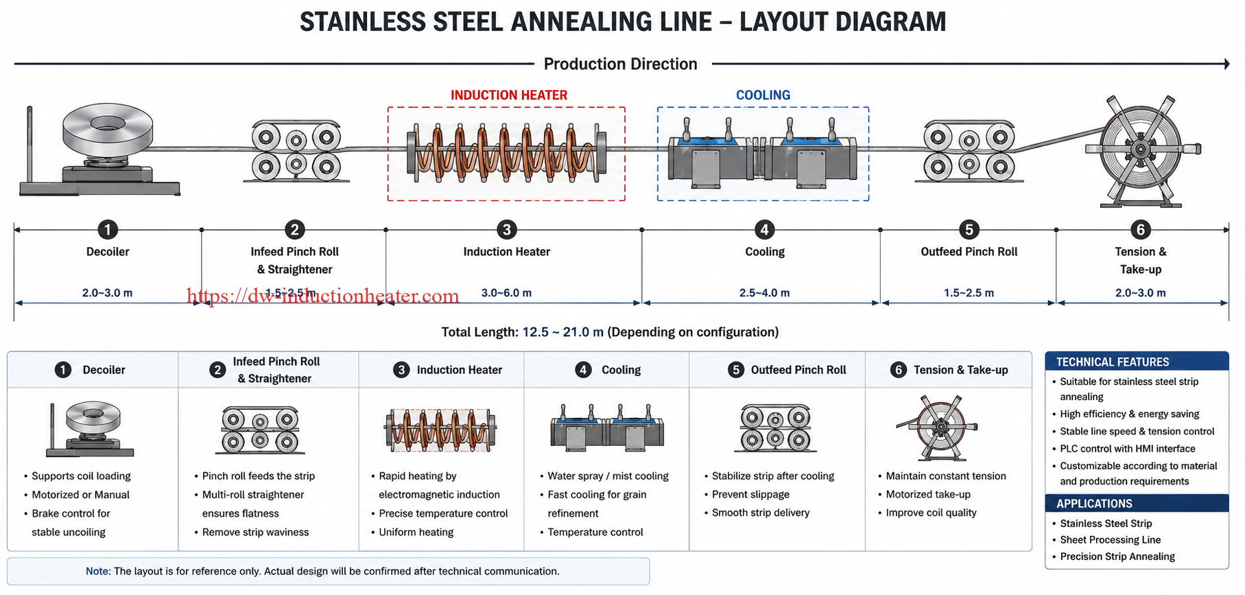
| Principle Element | Engineering Meaning | Control Method |
|---|---|---|
| Electromagnetic field | Transfers energy to the moving wire without contact | Coil design, frequency, power output |
| Skin effect | Current density is higher near the surface at higher frequency | Frequency selection according to diameter |
| Residence time | Time the wire remains inside the heating zone | Line speed and coil length |
| Temperature rise | Determines annealing degree | Power feedback and pyrometer control |
| Cooling rate | Affects final microstructure and surface condition | Air, water, gas or controlled cooling |
Basic Engineering Relationship
| Parameter | Effect on Annealing | Engineering Rule |
|---|---|---|
| Higher line speed | Shorter heating time | Requires higher power or longer coil |
| Larger wire diameter | More mass per meter | Requires higher power and sometimes lower frequency |
| Higher target temperature | More energy required | Requires power margin and better temperature feedback |
| Higher frequency | More surface-focused heating | Useful for small wires; may be less ideal for large cross-sections |
| Longer coil | Longer residence time | Can reduce required instantaneous power |
Key Technical Parameters
The parameters of a continuous induction annealing system must be selected based on material, diameter, line speed, target annealing temperature, surface requirement and available production space. For copper wire, annealing practice can vary widely depending on whether the goal is stress relief, partial softening or full recrystallization. Published technical examples and process disclosures show induction annealing of copper wire over very short time windows when higher temperatures are used; for example, one copper wire annealing method describes induction or resistance heating in the range of 650–1020°C for 0.3–5 seconds for specific interconnector wire applications.
| Power | Frequency | Temperature | Time | Coil | Cooling | Control |
|---|---|---|---|---|---|---|
| 10–50 kW | 30–300 kHz | 250–750°C depending on material | 0.5–10 s | Small multi-turn coil | Air / water / gas | Manual or PLC |
| 50–150 kW | 10–150 kHz | 300–900°C depending on material | 1–20 s | Longitudinal tunnel coil | Controlled cooling | PLC + pyrometer |
| 150–500 kW | 1–50 kHz | 400–1100°C depending on alloy | 2–60 s | Multi-zone coil system | Water/gas cooling | Closed-loop control |
Typical Temperature Ranges for Engineering Reference
| Material | Typical Annealing / Stress Relief Range | Process Notes |
|---|---|---|
| Copper wire | 250–700°C depending on speed and required softness | Lower temperatures need longer time; high-speed lines may use higher temperature and shorter time. |
| Oxygen-free copper | 250–650°C typical process window | Protective atmosphere may be used to reduce oxidation. |
| Aluminum wire | 250–450°C typical | Temperature must be controlled carefully to avoid over-softening. |
| Carbon steel wire | 500–750°C for stress relief / softening depending on grade | Exact process depends on carbon content and desired microstructure. |
| Stainless steel wire | 700–1100°C depending on grade and process target | Often requires protective gas for bright annealing. |
| Nickel alloy wire | 700–1150°C depending on alloy | Used for precision alloy property control. |
Line Speed, Coil Length and Residence Time Chart
| Line Speed | Coil Heating Length | Residence Time | Engineering Meaning |
|---|---|---|---|
| 10 m/min | 0.5 m | 3.0 s | Suitable for compact copper wire heating with sufficient power. |
| 30 m/min | 0.5 m | 1.0 s | Requires higher power or higher target temperature. |
| 60 m/min | 1.0 m | 1.0 s | High-speed line requires fast power response. |
| 120 m/min | 1.5 m | 0.75 s | Needs multi-zone heating or high power density. |
| 300 m/min | 3.0 m | 0.60 s | Requires advanced line synchronization and precise control. |
Engineering Selection Guide
Selecting a continuous induction annealing system requires more than choosing power. The supplier must understand the wire material, diameter range, drawing speed, required softness, surface condition, allowable oxidation, cooling method and production layout. A small copper wire line and a large steel wire line may both be called “continuous annealing,” but their equipment designs are very different.
| Condition | Recommended Equipment | Notes |
|---|---|---|
| Fine copper wire, high line speed | High-frequency induction annealing system with short multi-turn coil | Requires precise tension control and line-speed power synchronization. |
| Medium copper conductor | Medium/high-frequency induction annealing system with pyrometer feedback | Good for wire drawing line integration and conductor softening. |
| Flat copper or rectangular wire | Custom-shaped induction coil with edge temperature control | Coil design must avoid overheated edges and cold center. |
| Aluminum wire | High-efficiency induction heater with accurate temperature control | Aluminum overheats easily; use controlled power ramping. |
| Carbon steel wire | Medium-frequency or high-frequency annealing system depending on diameter | Magnetic coupling is strong; process must avoid surface scaling if exposed to air. |
| Stainless steel bright annealing | Induction annealing system with protective atmosphere chamber | Hydrogen, nitrogen-hydrogen or inert gas may be used depending on plant safety rules. |
| Existing drawing line retrofit | Compact inline induction module with PLC line-speed input | Requires mechanical integration with pay-off, capstan and take-up. |
| Multi-size production | Recipe-based induction power supply with adjustable coil or replaceable coil sets | Improves changeover speed and product flexibility. |
Power Selection Method
A preliminary power estimate can be made from the mass flow rate of the wire and the required temperature rise. In real production, a safety margin must be added for coil loss, radiation, convection, surface condition, cooling loss and line acceleration.
| Calculation Item | Formula / Meaning | Engineering Note |
|---|---|---|
| Wire cross-section area | A = πd² / 4 for round wire | Use actual diameter after drawing. |
| Mass flow rate | ṁ = A × density × line speed | Line speed must be converted to m/s. |
| Thermal power | P = ṁ × Cp × ΔT | Basic sensible heat calculation. |
| Practical equipment power | Pactual = P / efficiency × safety margin | Commonly add 15–30% margin for production stability. |
Example Power Reference for Copper Wire
| Copper Wire Diameter | Line Speed | Approximate Heating Duty | Suggested Equipment Range |
|---|---|---|---|
| 0.5–1.0 mm | 100–500 m/min | Low mass flow but high speed | 10–60 kW high-frequency system |
| 1.0–3.0 mm | 50–250 m/min | Medium mass flow | 30–150 kW system |
| 3.0–8.0 mm | 10–120 m/min | Higher thermal load | 80–300 kW system |
| Rectangular conductor | Customized | Depends on cross-section | Custom coil and power calculation required |
Control System Selection
| Control Function | Recommended Design | Purpose |
|---|---|---|
| Line-speed synchronization | PLC receives encoder signal from drawing line | Automatically adjusts power when speed changes. |
| Temperature feedback | Infrared pyrometer or contact measurement | Maintains stable annealing temperature. |
| Recipe storage | Store material, diameter and speed settings | Reduces setup error during product changeover. |
| Tension monitoring | Dancer arm, load cell or drive feedback | Prevents wire breakage and diameter instability. |
| Cooling control | Water/gas flow and temperature monitoring | Protects surface quality and final properties. |
| Alarm protection | Overcurrent, overvoltage, water shortage, overtemperature | Protects equipment and production line. |
Process Workflow
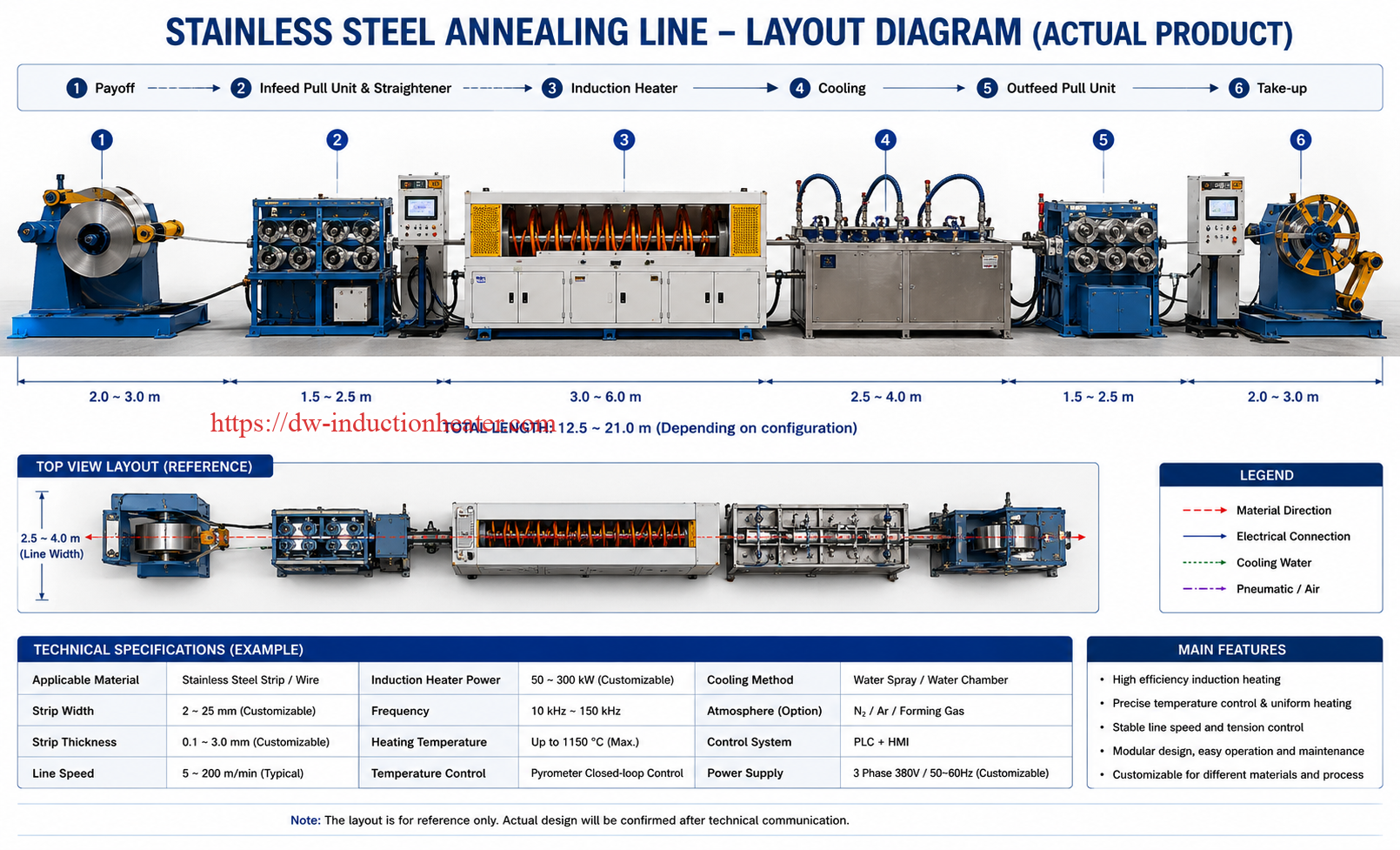
A continuous induction annealing line should be designed as an integrated process, not as a standalone heater. The heating system must work with pay-off, drawing capstan, cleaning unit, tension control, cooling section, drying system and take-up device.
- Wire pay-off: The cold-drawn wire or conductor is fed from the pay-off reel with stable tension.
- Pre-cleaning: Drawing lubricant, oil, dust or oxide is removed if required by product quality.
- Diameter and speed confirmation: PLC receives product recipe and line-speed signal.
- Induction coil positioning: Wire passes through the center of the induction coil or tunnel heating zone.
- Induction heating: The wire is heated rapidly to the target annealing temperature.
- Temperature monitoring: Pyrometer or sensor checks outlet temperature and sends feedback to the power supply.
- Atmosphere protection: Nitrogen, inert gas or reducing atmosphere may be used for bright annealing.
- Controlled cooling: Wire is cooled by air, water, mist, gas or controlled cooling chamber.
- Drying and surface treatment: Water is removed and surface condition is stabilized before take-up or extrusion.
- Tension control: Wire tension is managed to prevent stretching or breakage.
- Take-up or next process: The annealed wire is wound or sent directly to stranding, extrusion or coating.
- Quality inspection: Elongation, tensile strength, surface quality, conductivity and diameter stability are checked.


Inline Process Layout Chart
| Line Section | Main Equipment | Control Requirement |
|---|---|---|
| Pay-off | Pay-off stand, brake, tension unit | Stable feed and no wire vibration |
| Pre-treatment | Cleaner, wiping device, straightener | Clean and centered wire path |
| Heating zone | Induction coil, power supply, workhead | Power follows speed and material recipe |
| Temperature control | Pyrometer, PLC, feedback loop | Stable outlet temperature |
| Cooling zone | Air, water, gas or chamber cooling | Controlled final property and surface |
| Post-treatment | Dryer, surface inspection, tension control | Prevent corrosion, scratches and breakage |
| Take-up | Winder, dancer, traversing unit | Stable winding tension and coil quality |
Case Study / Typical Application
The following examples show how continuous induction annealing can be applied in different wire and cable production environments. The values are engineering references; final parameters should be confirmed by sample testing and actual production requirements.
| Industry | Material | Equipment | Heating Parameters | Result |
|---|---|---|---|---|
| Motor wire production | Square copper wire | 45 kW induction heating system with custom coil | Continuous annealing at about 15 m/min in published application example | Reduced work hardening after drawing and improved wire formability. |
| Electrical cable conductor line | Round copper wire | High-frequency continuous induction annealing system | Power follows drawing speed; protective gas optional | Improved elongation, stable conductor softness and reduced wire breakage. |
| Aluminum conductor production | Aluminum wire | Medium/high-frequency induction heater with closed-loop control | Moderate temperature, fast response, controlled cooling | Better ductility after drawing and stable cable forming behavior. |
| Stainless steel wire plant | Stainless steel wire | Induction heater with protective atmosphere chamber | High-temperature annealing with controlled atmosphere | Reduced residual stress and improved surface quality. |
| Spring and precision wire production | Special alloy wire | Multi-zone induction annealing system | Recipe-based temperature control and controlled cooling | More stable mechanical properties and lower failure risk in forming. |
 Typical Quality Targets
| Quality Target | Measurement Method | Why It Matters |
|---|---|---|
| Elongation | Tensile test | Confirms ductility recovery after annealing. |
| Tensile strength | Tensile tester | Ensures wire is not too hard or over-softened. |
| Electrical conductivity | Conductivity meter | Important for electrical wire and cable conductors. |
| Surface color | Visual or optical inspection | Indicates oxidation, overheating or atmosphere problems. |
| Diameter stability | Laser micrometer | Ensures drawing and annealing do not disturb dimensional quality. |
| Breakage rate | Production line record | Directly affects yield and production cost. |
Common Problems and Solutions
Most continuous annealing problems come from unstable line speed, poor temperature control, wrong frequency, poor coil alignment, insufficient cleaning, poor tension control or unsuitable cooling. The table below summarizes common production issues and practical engineering solutions.
| Problem | Cause | Solution |
|---|---|---|
| Wire is still too hard after annealing | Temperature too low, residence time too short or power insufficient | Increase power, reduce line speed, lengthen coil or adjust target temperature. |
| Wire becomes too soft | Overheating or excessive residence time | Reduce power, increase line speed or use closed-loop temperature feedback. |
| Surface oxidation or discoloration | High temperature exposure in air | Use protective atmosphere, shorten heating time or improve cooling protection. |
| Uneven temperature along wire | Line speed fluctuation or unstable power | Synchronize power with line encoder and use stable tension control. |
| Hot spots on wire | Wire not centered in coil or coil field uneven | Improve guide rollers, coil centering and coil geometry. |
| Wire breakage after annealing | Over-softening, tension shock or poor cooling transition | Optimize tension control, cooling rate and annealing temperature. |
| Low conductivity stability | Overheating, contamination or inconsistent process | Improve cleaning, temperature control and material traceability. |
| Coil overheating | Insufficient cooling water, scale or excessive load | Check water flow, pressure, conductivity and chiller capacity. |
| Production speed cannot increase | Power too low or heating zone too short | Select higher power supply or use multi-zone induction heating. |
| Inconsistent product changeover | No recipe management or manual setting errors | Use PLC recipe control for material, diameter and line speed. |
FAQ
1. What is continuous induction annealing for wire and cable?
Continuous induction annealing is an inline process that heats moving wire or cable conductors with electromagnetic induction to reduce work hardening, restore ductility and stabilize mechanical properties. The wire passes continuously through an induction coil and is then cooled under controlled conditions.
2. Why is wire annealing needed after drawing?
Cold drawing reduces wire diameter but increases hardness and internal stress. Annealing softens the wire, improves elongation and reduces breakage during further drawing, stranding, bending, insulation extrusion or winding.
3. Can copper wire be annealed by induction heating?
Yes. Copper wire is a common application for continuous induction annealing. Induction heating can soften copper wire after drawing and improve flexibility for electrical, motor and cable applications. Published examples include continuous copper wire annealing using a custom induction coil and 45 kW system at around 15 m/min.
4. What temperature is used for copper wire induction annealing?
The temperature depends on wire diameter, line speed, material grade and required softness. Engineering practice may use lower temperatures with longer time or higher temperatures with very short residence time. Some copper wire induction or resistance annealing methods describe temperatures from 650°C to 1020°C for very short heating times of 0.3–5 seconds in specific applications. [oai_citation:6‡Google 专利](https://patents.google.com/patent/US20140224387A1/en?utm_source=chatgpt.com)
5. Is induction annealing suitable for aluminum wire?
Yes. Aluminum wire can be annealed by induction heating, but the process must be controlled carefully because aluminum has high thermal conductivity and can be over-softened if temperature is too high. Accurate temperature control and line-speed synchronization are important.
6. What frequency is used for wire induction annealing?
Fine wire usually uses higher frequency, while larger diameter wire may use lower frequency for better heat penetration. Typical systems may use frequencies from a few kHz to hundreds of kHz, depending on material, diameter and required temperature uniformity.
7. How is oxidation controlled during wire annealing?
Oxidation can be reduced by shortening heating time, using protective gas, installing a closed atmosphere chamber, improving wire cleaning and controlling cooling. Stainless steel and bright copper applications may require nitrogen, inert gas or reducing atmosphere depending on the process.
8. Can induction annealing be integrated into an existing wire drawing line?
Yes. A compact induction annealing module can often be installed inline between drawing, cleaning, cooling and take-up sections. The key is to synchronize induction power with line speed and maintain stable wire tension through the heating zone.
9. How do I choose the correct power for a wire annealing system?
Power depends on wire material, diameter, line speed, target temperature and coil length. A preliminary calculation uses mass flow rate and temperature rise, then adds efficiency and safety margin. Final selection should be confirmed by production speed and sample testing.
10. What information is needed for a quotation?
Please provide wire material, diameter range, cross-section shape, line speed, target annealing temperature, required mechanical properties, surface requirement, available voltage, cooling water condition, production layout and whether protective atmosphere is required.
Conclusion
Continuous induction annealing for wire and cable is a practical solution for modern conductor and wire production. It helps recover ductility, reduce work hardening, stabilize mechanical properties and improve production efficiency after drawing or forming. Compared with traditional batch or furnace annealing, induction heating offers faster response, compact layout, easy automation and direct integration with continuous production lines.
For copper wire, aluminum wire, steel wire, stainless steel wire and special alloy wire, the key to success is correct equipment selection. Engineers must evaluate wire diameter, material, line speed, target temperature, coil length, cooling method, surface requirement and control system. A well-designed continuous induction annealing system should include an efficient induction power supply, properly designed coil, temperature feedback, tension control, cooling system and PLC recipe management.
HLQ Induction Equipment can provide customized continuous induction annealing systems for wire and cable applications. To receive an engineering proposal, provide your wire material, diameter range, line speed, required softness or elongation, target temperature, production layout and available power supply. Based on these details, the system can be designed for stable inline annealing, better wire quality and higher production efficiency.