Induction Preheat Welding Systems

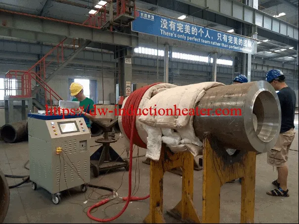
Portable Post Weld Heating Treatment System With Induction 

Main Application:

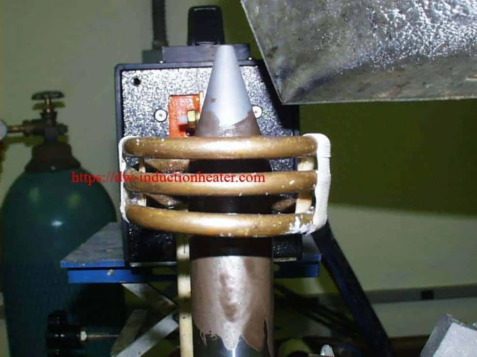
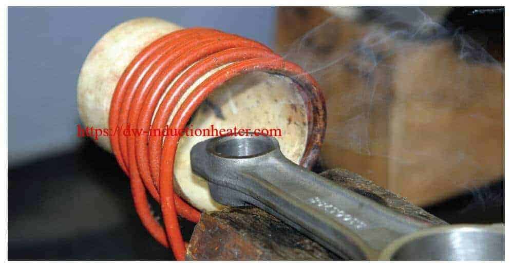
l  Preheat: weld heat,coating, spraying, bending, fitting&unfitting heat

l  Post-weld heat treatment: tank, boile, pipeline, steel sheet or other metal jobs

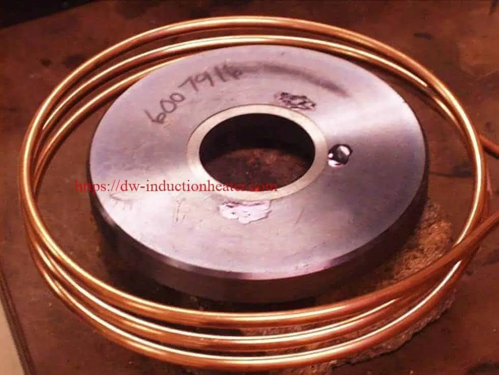
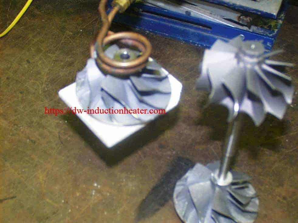
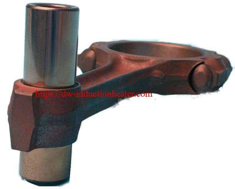
l  InductionHeat: mold heating, shipboard, zinc bath, large& irregular metal parts

l  Pipeline material heat: pipeline oil, pipeline gas, pipeline water, pipeline petrochemical and other pipeline material

Main Features

* High speed: 70%

*  Low tolerance

*  Energy Saving

*  High efficiency

*  Accurate heating

*  Simple operation

*  Non-contact heating

*  Environmental protection

*  Hypothermia circumstance

* Air cooling is suitable for low-temperature environment

* Induction heating is more uniform than oil,gas,flame heating
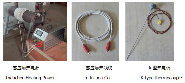
 portable post weld heating treatment system

MYD-20KWMYD-10KW
Input voltage3*380V, 50/60Hz, 4 Wires
Input Current1~30A1~15A
Output Current0~300A0~200A
Output Power1~20KW1~10KW, Max 15KW, 150% duty cycle
Output Frequency5~30KHZ
ThermocoupleK type
Temperature systemBuild in induction machine
Heating TemperatureMax800℃Max500℃
Size700 x 330 x 410 mm650 x 310 x 410 mm
Weight32kg26 kg
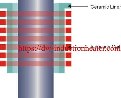
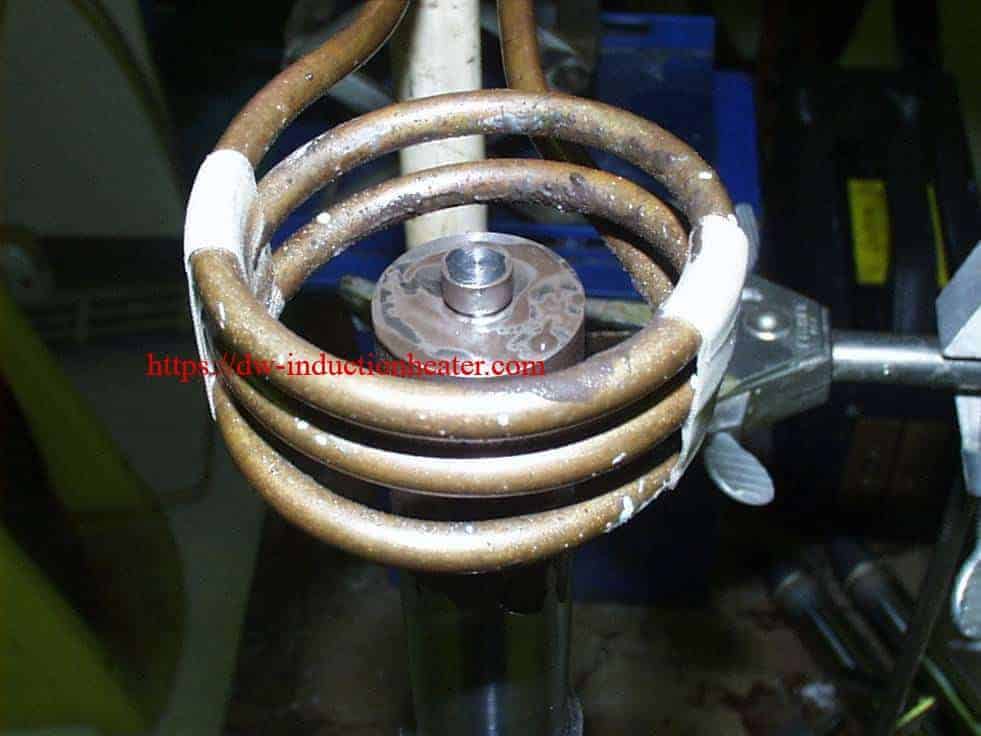
Induction Heating coil
Length10~20 M
Diameter15 mm
Working temperature-30~45℃
Pipeline SizeOD: 50~500mm or equivalent

Induction Preheating Hot Rod Heading

induction preheating process

Induction Preheating Hot Rod Heading With IGBT Heating Units

Objective Heat a waspaloy rod to 1500ºF (815.5ºC) for hot heading application
Material Waspaloy rod 0.5” (12.7mm)OD, 1.5” (38.1mm) length, ceramic liner
Temperature 1500 ºF (815.5ºC)
Frequency 75 kHz
Equipment • DW-HF- 20 kW induction heating system, equipped with a remote workhead containing two 1.32μF capacitors for a total of .66μF
• An induction heating coil designed and developed specifically for this application.
Process A seven turn helical coil is used to heat the rod. The rod is placed inside the coil and power is applied for two seconds
providing enough heat to penetrate the inner core. An optical pyrometer is used for close loop temperature control and a
ceramic liner is used so the rod does not touch the coil.
Results/Benefits Induction heating provides:
• Low pressure and minimal residual stress
• Better grain flow and microstructure
• Even distribution of heating
• Improved production rates with minimal defects

Preheating Hot Rod Heading

Induction Brazing Carbide To Stainless Steel

Induction Brazing Carbide To Stainless Steel Shaft With IGBT Heating Units

Objective Brazing a cone shaped carbide to a stainless steel shaft for a digger
Material Cone shaped carbide 1.12” (28.4mm) dia, 1.5”(38.1mm) tall, stainless steel shaft 1.12” (28.4mm) dia and various length, black brazing flux and braze shims
Temperature 1500 ºF (815 ºC)
Frequency 277 kHz
Equipment • DW-UHF-10 kW induction heating system, equipped with a remote workhead containing two 1.0μF capacitors for a total of 0.5μF
• An induction heating coil designed and developed specifically for this application.
Process A three turn helical coil is used to braze the carbide to the shaft. The steel shaft is fluxed and the braze shim placed on top. The carbide tip is fluxed and placed on top of the shim, lining up the countersunk hole in the carbide. The hole is not fluxed because the flux outgases and causes the carbide to build up pressure and attempt to repel from the shaft. Power is applied for 85 seconds for the braze shim to flow and make a good joint.
DAWEI’s customer has a customer who is unhappy with the braze quality of their digger so our customer is looking for a better quality brazing process. DAWEI’s customer is very happy with the sample brazed diggers and the help he received from the Ameritherm lab in developing his brazing process.
Results/Benefits Induction heating provides:
• Rapid localized heating only where needed
• Creates clean, controllable joints
• Hands-free heating that involves no operator skill for manufacturing
• Even distribution of heating

brazing carbide to shaft


induction brazing carbide to shaft


brazing carbide to stainless steel shaft

High Frequency Induction Cap Sealing

High Frequency Induction Cap Sealing With IGBT heating units

Objective To heat an aluminum foil inside a plastic shampoo cap for sealing
Material 2.0” diameter, plastic flip top cap, with a 0.9” diameter aluminum foil seal
Temperature 250 – 300 ºF (120 – 150 °C)
Frequency 225 kHz
Equipment DW-UHF-7.5 kW, induction heating system, equipped with a remote heat station containing two 1.5 μF capacitors (total capacitance 0.75 μF).
An induction heating coil designed and developed specifically for this application.
Process A three-turn two-position helical coil is used to heat the aluminum foil in a tunnel style assembly. Product (containers)
passes easily under the induction coil. The assembly is located such that the entire perimeter of the aluminum foil is heated
uniformly. The container and cap is placed under the coil and RF power delivered for 0.12 seconds. The aluminum foil heats
and seals to the plastic of the cap.
Results/Benefits This induction heating configuration fulfills the process
requirements and:
• uses a simple, economical coil design
• increases throughput with a dual-position coil
• delivers quality, consistent seals
• offers a repeatable process, well-suited for automation

induction cap sealing

Heating Aluminum Foil For Cap Sealing

Induction Heating Aluminum Foil For Cap Sealing with IGBT inductive heater

Objective An induction heater is used to heat a polymer laminated aluminum foil in 0.5 to 2.0 seconds. The heat produced in the aluminum foil melts the polymer that bonds to the neck of a plastic container.
Material Aluminum foil, polyethylene, polypropylene, polyvinylchloride, polystyrene, polyethylene terephthalate, styrene acrylonitrile
Temperature 300 – 400 (ºF), 149 – 204 (ºC)
Frequency 50 to 200 kHz
Equipment DAWEI solid-state induction power supplies operating between 1 & 10 kW at frequencies of 50- 200 kHz. These units operate with remote sealing heads which allows the main power cabinet of the equipment to be located away from the immediate production area. Distances of up to 100 meters are possible. The microprocessor is used to control
and protect the system and ensures that the optimal operating frequency is maintained at all times and that each container
receives the same amount of heat energy from cycle to cycle.
Process Two different types of aluminum foil laminates are available for this application. The first assembly includes backing
board/reseal, a wax layer, aluminum foil, and a heatseal film for supported systems (Figure 1). The second assembly includes a high temperature film, aluminum foil, and a heatseal film for unsupported systems (Figure 2). The procedure is to fit the foil membrane into the cap and to fit the cap to the container after the product is filled.
Results For the aluminum foil assembly as shown in Figure 1, heat induced in the metallic foil by the induction coil almost
instantaneously melts the polymer coating and the neck of the container forming a hermetic seal between the heat seal film
and the rim of the container. The heat also melts the wax between the aluminum foil and the back board. The wax is
absorbed into the back board. This results in an air tight bond between the aluminum foil/membrane and the rim of the
container, the back board is released and remains in the cap.

Process (cont’d) In the case of unsupported membranes in Figure 2, one side of the aluminum foil is coated with a heat sealable polymer film and this face that will be in contact with and sealed to the container. The other side of the foil that will be in contact with the cap has a higher melting-point film that prevents adhesion of the aluminum to the cap allowing the end user to unscrew the cap. Unsupported membranes are typically used where the end user pierces the tamper evident membrane prior to dispensing the product. The aluminum foil acts as a vapor barrier preserving the freshness of the product and prevents it from drying.

induction heating aluminum foil cap sealing

Shrink Fit Steel Gear onto Shaft

Shrink Fit Steel Gear onto Shaft With High Frequency Induction Heating Units

Objective Heat the bore of a hardened spur steel gear to shrink fit onto a gear motor shaft. This is part of a chair for the disabled.
Material Steel gear 2.5” (63.5mm) OD, .75” (19mm) ID x .625” (16mm) thick, temperature indicating paint
Temperature 400 ºF (204 ºC)
Frequency 300 kHz
Equipment • DW-UHF-3.2 kW induction heating system, equipped with a remote workhead containing two 0.66 μF capacitors for a total of 1.32 μF
• An induction heating coil designed and developed specifically for this application.
Process A four turn helical internal coil is used to heat the gear bore.
The coil is inserted into the gear bore and power is applied for 90 seconds to reach the required 400 ºF (204 ºC) and expand
the gear bore. The gear is then placed on the shaft and allowed to cool, creating the shrink fit between the gear and
the shaft.
Results/Benefits Induction heating provides:
• No pre-heat cycle, heat is available on demand
• Energy efficient, heats only the part, not the atmosphere around it
• Controlled, even distribution of heating
• Faster production times

Shrink Fit Steel Gear onto Shaft

Induction Shrink Fitting Carbide Ring

Induction Shrink Fitting Carbide Ring With IGBT Induction Heating Units

Objective Shrink fitting a carbide ring into a steel valve seat
Material Steel valve seat 6” (152.4mm) OD with 3” (76.2mm) ID hole & .75” (19mm) thick, carbide ring
Temperature 500 ºF ( 260 ºC)
Frequency 85 kHz
Equipment •DW-HF-15kW induction heating system, equipped with a remote workhead containing two 0.50 μF capacitors for a total of 0.25 μF
• An induction heating coil designed and developed specifically for this application.
Process A three turn helical coil is used to heat the steel valve seat.
The steel valve seat is placed in the coil and heated for 50 seconds to enlarge the center hole & drop the carbide ring in
for the shrink fitting process.
Results/Benefits Induction heating provides:
• Accurate and repeatable results
• Ease of integration into existing production lines
• Energy efficient, only heats the part, not the atmosphere around it
• Hands-free heating that involves no operator skill for manufacturing
• Even distribution of heating

shrink fitting carbide ring


Induction Shrink Fit Aluminum Shaft

Induction Shrink Fit Aluminum Shaft with IGBT induction heating systems

Objective Heat aluminum impeller blades to 200 ºF (93 ºC) and shrink fit onto a shaft.
Material Aluminum impeller blades with a .28” (7.109mm) bore, aluminum shaft
Temperature 200 ºF (93 ºC)
Frequency 255 kHz
Equipment • DW-UHF-6W induction heating system, equipped with a remote workhead containing one 1.0μF capacitor.
• An induction heating coil designed and developed specifically for this application.
Process A split two turn helical coil is used to evenly heat the opening on the impeller blade. The impeller blade is heated for 20 seconds to reach the 200 ºF (93 ºC). The impeller blades are then removed from the coil & slipped over the shaft to complete the shrink fitting application.
Results/Benefits Induction heating provides:
• Repeatable results
• Reduced cycle time, lower consumables cost
• Even distribution of heating

Shrink Fit Aluminum


Shrink Fit Aluminum with induction

Inductioin Shrink Fitting Aluminum Pulley

Inductioin Shrink Fitting Aluminum Pulley With IGBT Heating Units

Objective Heat aluminum pulley for insertion of an inner bearing for the automotive industry
Material Aluminum pulley 2.3” (60mm) OD x 1.6” (40mm) ID x 1” (27mm) high and inner bearing 0.7” (17.8mm) high x 1.6” (40mm) dia
Temperature 464 ºF (240 ºC)
Frequency 283 kHz
Equipment • DW-UHF-4.5kW induction heating system, equipped with a remote workhead containing two 0.33μF capacitors for a total of 0.66μF
• An induction heating coil designed and developed specifically for this application.
Process A three turn helical coil is used to heat the aluminum pulley.
The pulley is heated to 464 ºF (240 ºC) in 20 seconds to expand the inner diameter and then the inner bearing is inserted to form the completed part.
Results/Benefits Induction heating provides:
• Defined and controlled heat pattern
• Process easily integrated into automated system
• Even distribution of heating

shrink fitting aluminum bearing


Shrink Fitting Assemble Connecting Rods

Induction Shrink Fitting Assemble Connecting Rods With IGBT Heating Units

Objective Assemble connecting rods with a more accurate control of the heat
Material Rod has an OD of .9125” (23.18mm), knuckle has an ID of .9125” (23.18mm) with an interference of .0001” (.0025mm). Knuckle assembly is forged steel
Temperature 400 ºF (204 ºC)
Frequency 210 kHz
Equipment • DW-UHF- 3.5 kW induction heating system, equipped with a remote workhead containing two 1.0μF capacitors for a total of 0.5 μF
• An induction heating coil, designed and developed specifically for this application.
Process A six turn helical coil is used to heat the connecting rod for 13 seconds. The coil is perpendicular to the axis of the bore to promote even heating around the circumference. The connecting rod is then assembled with the piston for shrink fitting.
Results/Benefits Induction heating provides:
• More accurate control of heat vs a flame burner. Only heats knuckle, not the whole part.
• Lower temperature used to prevent discoloring.
• Increased productivity due to repeatability & ease of operation. A foot pedal & timer is used.
• No product contamination.


Shrink Fitting Assemble Connecting Rods


Induction Shrink Fitting Assemble Connecting Rods

=