

Induction Melting Glass
Induction Melting Glass with a Metal Susceptor Vessel for Fiberglass Drawing
Quick Answer
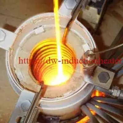
Induction melting glass uses an induction coil to heat an electrically conductive susceptor, here a metal vessel. The hot vessel then melts the glass by conduction and radiation. This is needed because glass is not electrically conductive when cold.
In this HLQ application, a specially designed coil shaped to the vessel heated it to 2200 °F (≈ 1204 °C) in 11 minutes, against a 25-minute target. The vessel was then held at 2200 °F so the glass could be melted for fiber drawing.

What is Induction Melting Glass?
Induction melting glass is indirect induction heating. Glass cannot carry the eddy currents that an induction coil induces. Instead, the coil heats a conductive vessel or susceptor, and the vessel transfers the heat to the glass.
This method is described in HLQ’s article on induction susceptor heating. It brings the control, efficiency and fast ramp-up of an induction power supply to non-conductive materials such as glass and ceramics.
| Item | HLQ case data |
|---|---|
| Objective | Heat a metal susceptor vessel to 2200 °F within 25 minutes for a fiberglass melting application |
| Material | Metal susceptor vessel |
| Temperature | 2200 °F (≈ 1204 °C) |
| Frequency | 300 kHz |
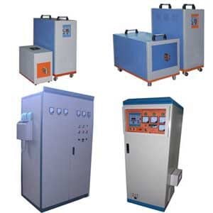
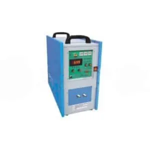
| Equipment | DW-MF-70kW induction heating power supply, remote heat station and a specially designed induction coil |
| Time to temperature | 11 minutes |
| Drain tube | An additional 3 kW power supply suggested for emptying the glass through the drain tube |
| Result | Uniform and repeatable heating; the vessel can be held at 2200 °F for glass melting and fiber drawing |
Key Applications

| Application | Heated part | Temperature | Time | Frequency | Equipment |
|---|---|---|---|---|---|
| Fiberglass melting (this page) | Metal susceptor vessel | 2200 °F (≈ 1204 °C) | 11 min | 300 kHz | DW-MF-70kW |
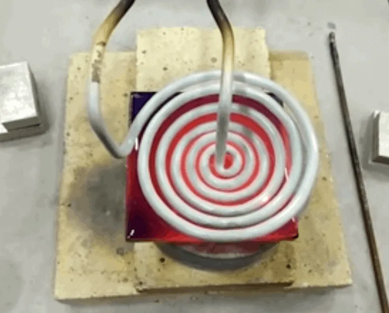
| Glass reflow for X-ray tubes | Graphite susceptor, glass disc 25 × 3 mm, nitrogen atmosphere | 950 °C (1742 °F) | 32 s | 80 kHz | DW-HF-25kW |
| Hermetic glass seal of resistors | Kovar ring, glass tube ≈ 0.1 in diameter | 482 °C (900 °F) | 500 ms per side | 324 kHz | DW-UHF-6kW-III |
Case details: induction heating graphite susceptor for glass reflow and induction sealing glass.

Suitable Materials
| Role | Material | Source |
|---|---|---|
| Material processed | Glass (melting for fiber drawing, reflow, glass-to-metal sealing) | HLQ glass cases |
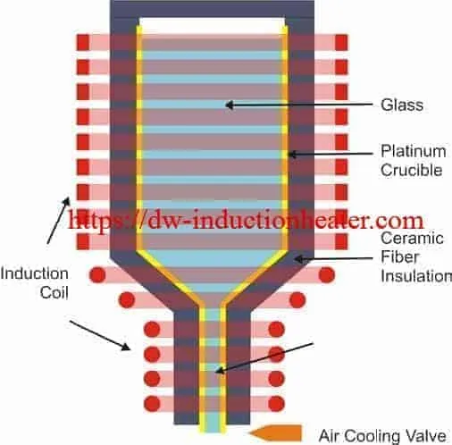
| Susceptor vessel | Metal vessel; platinum crucible shown in the original diagram | This page |
| Other susceptor materials | Silicon carbide, molybdenum, graphite, stainless steels | HLQ susceptor heating article |
| Graphite susceptor | Glass reflow in X-ray tube manufacturing | HLQ graphite susceptor case |
| Kovar ring | Glass-to-metal hermetic seal | HLQ glass sealing case |
| Insulation | Ceramic fiber insulation around the vessel | Original diagram |
Choose the susceptor material carefully. Its reactivity with the surrounding environment decides reliability, and the wrong material can cause contamination.
Working Principle

- Power: The induction power supply feeds a remote heat station, which feeds the coil.
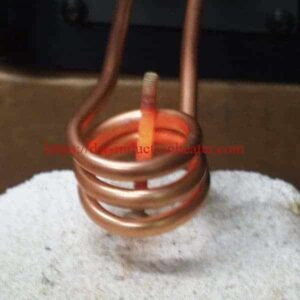
- Coil: The coil is shaped to conform to the vessel, so the vessel heats uniformly.
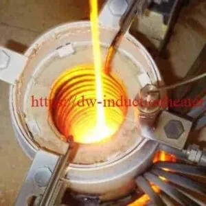
- Eddy currents: The alternating field induces eddy currents in the metal vessel wall, and the wall heats up.
- Heat transfer: The vessel heats the glass by conduction where they touch, and by radiation.
- Outlet: A separate coil on the drain tube keeps the outlet hot when the glass is emptied. The original diagram also shows an air cooling valve at the outlet.
Background: how an induction heater works.
| Direct induction heating | Susceptor heating (this application) | |
|---|---|---|
| Heated part | The conductive workpiece itself | A conductive susceptor (metal vessel, graphite, SiC) |
| Material processed | Metals | Non-conductive materials such as glass, ceramics, plastics |
| Heat transfer | Generated inside the part | Conduction (contact) or radiation (separated) |
Technical Specifications
| Parameter | Value in the HLQ fiberglass case |
|---|---|
| Heated part | Metal susceptor vessel |
| Set temperature | 2200 °F (≈ 1204 °C) |
| Target time to temperature | 25 minutes |
| Achieved time to temperature | 11 minutes |
| Frequency | 300 kHz |
| Main power supply | DW-MF-70kW |
| Heat station | Remote heat station |
| Coil | Specially designed coil shaped to conform to the vessel |
| Drain tube heating | Additional 3 kW power supply suggested |
| Operation | Vessel held at 2200 °F for fiber drawing |
Reference: current penetration depth in the vessel wall
| Frequency | Platinum, ρ ≈ 0.5 µΩ·m | Stainless steel, ρ ≈ 1.25 µΩ·m |
|---|---|---|
| 10 kHz | ≈ 3.6 mm | ≈ 5.6 mm |
| 30 kHz | ≈ 2.1 mm | ≈ 3.2 mm |
| 80 kHz | ≈ 1.3 mm | ≈ 2.0 mm |
| 300 kHz | ≈ 0.65 mm | ≈ 1.0 mm |
Calculated with δ = 503·√(ρ / (µr·f)), µr = 1, using typical resistivity near 1200 °C. Thinner vessel walls favour higher frequency.

Recommended Model Selection
| HLQ series | Power range | Frequency range | Supply | Glass-related HLQ case |
|---|---|---|---|---|
| DW-UHF | 4.5–60 kW | 50 kHz – 2.0 MHz (by model) | 1-ph 220 V / 3-ph 380 V | Glass-to-metal seal: DW-UHF-6kW-III, 324 kHz |
| DW-HF | 15–160 kVA | 20–80 kHz (15 kVA: 30–100 kHz) | 3-ph 380 V (15 kVA: 1-ph 220 V) | Glass reflow: DW-HF-25kW, 80 kHz |
| DW-MF | 15–300 kW | 1–20 kHz | 3-ph 380 V | Fiberglass melting vessel: DW-MF-70kW |
Full model data: HLQ induction heating device models. The final model, coil and frequency are confirmed by an initial heating test on your vessel.
Non-induction alternatives for crucible glass melting
| Furnace | Heating | Temperature | Crucible |
|---|---|---|---|
| KSS glass melting furnace | MoSi₂ resistance elements | KSS-1400 / 1600 / 1700; max. 1720 °C | 1, 3, 5, 10, 20 L |
| GWL glass frit furnace | SiC or MoSi₂ resistance elements | 1200–1800 °C working | 1.6–17 L, high-purity zirconium quartz |
See the 1700 °C glass melting furnace and the glass frit furnace.
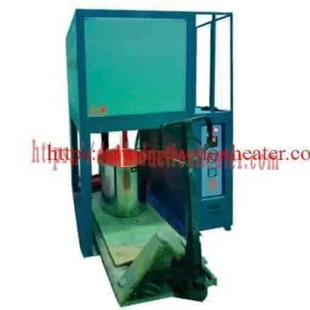
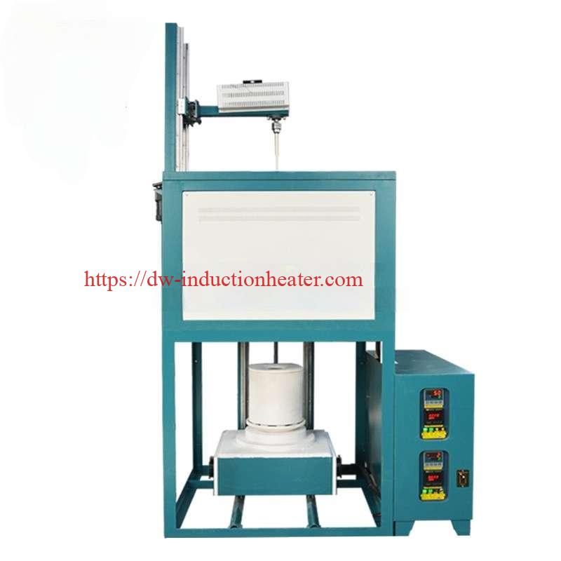
Process Workflow

| Step | Action | Case reference |
|---|---|---|
| 1 | Design a coil shaped to conform to the vessel | Specially designed coil |
| 2 | Run initial tests to set the heating pattern and time to temperature | Initial tests |
| 3 | Load the glass into the vessel | Fiberglass melting |
| 4 | Apply power and heat the vessel to 2200 °F | Reached in 11 min |
| 5 | Hold the vessel at 2200 °F while the glass melts | Vessel held at 2200 °F |
| 6 | Heat the drain tube when emptying | Additional 3 kW supply suggested |
| 7 | Draw fiber from the molten glass at the outlet | Fiber drawing |
Station layout

Common Problems and Solutions
| Problem | Likely cause | Solution |
|---|---|---|
| Uneven vessel temperature | The coil does not follow the vessel shape | Use a coil shaped to conform to the vessel; check the heating pattern in initial tests |
| Glass freezes in the drain tube when emptying | The drain tube is outside the main coil | Heat the drain tube separately (the case suggests an additional 3 kW supply) |
| Time to temperature too long | Power or coil coupling not matched to the vessel | Confirm power, frequency and coil by test before production |
| Contamination or short susceptor life | Susceptor material reacts with its environment | Select a susceptor material compatible with the glass and atmosphere |
| Arcing on very small parts | High frequency on small parts | In the HLQ glass sealing case, medium frequency was chosen to avoid arcing |
| Poor heating of a thin vessel wall | Frequency too low for the wall thickness | Check penetration depth against wall thickness (see the reference table) |
Engineering Selection Guide
| Factor | What to confirm | Why it matters |
|---|---|---|
| Vessel material and wall thickness | Platinum, stainless steel, graphite, other | Sets the frequency and power density |
| Vessel shape and size | Drawing with the drain tube | The coil must conform to the vessel |
| Glass type and charge | Composition and weight per batch | Sets the hold temperature and heat demand |
| Target temperature and time | For example 2200 °F within 25 min | Sets the power supply rating |
| Outlet and drain tube | Size and heating need | A separate small supply may be needed |
| Atmosphere | Air or inert gas | Affects the choice of susceptor material |
| Utilities | Voltage, cooling water | Needed for the power supply, heat station and coil |
| Induction or resistance | Susceptor vessel process or lab crucible melting | For 1–20 L lab crucibles, compare the KSS glass melting furnace |
For melting metals rather than glass, see the induction melting furnace.
Advantages and Limitations
| Advantages | Limitations |
|---|---|
| Uniform, repeatable heating with a coil shaped to the vessel | Glass cannot be heated directly; a conductive susceptor is required |
| Fast time to temperature: 11 minutes against a 25-minute target in the HLQ case | The coil must be designed and tested for each vessel |
| The susceptor can be heated through quartz, glass or other non-conductive chambers | The drain tube needs its own heating |
| The hot susceptor needs no connection to a high-current conductor | Susceptor material must be compatible with the glass and atmosphere |
| Temperature is set by the power supply | Heat reaches the glass only through conduction and radiation from the vessel |
Why Choose HLQ?
| Strength | Evidence |
|---|---|
| Custom coil design | Coil shaped to conform to the vessel in this case |
| Test-based process development | Heating pattern and time to temperature set by initial tests |
| Glass application experience | Fiberglass melting, glass reflow and glass-to-metal sealing cases |
| Three power supply series | DW-UHF, DW-HF and DW-MF |
| Complete system | Power supply, remote heat station and coil |
| Resistance options | KSS and GWL furnaces for crucible glass melting |
10 Core FAQs
1. Can glass be heated directly by induction?
Not when cold, because glass is not electrically conductive. A conductive susceptor such as a metal vessel or graphite is heated, and it heats the glass.
2. What temperature was reached in this HLQ case?
2200 °F (about 1204 °C).
3. How long did it take?
11 minutes of heating, against a 25-minute target.
4. Which equipment was used?
A DW-MF-70kW induction heating power supply, a remote heat station and a specially designed coil.
5. Why is a separate supply suggested for the drain tube?
To keep the outlet hot when the glass is emptied through the drain tube. An additional 3 kW supply was suggested.
6. What is the molten glass used for in this case?
Fiber drawing. The vessel is held at 2200 °F so the glass stays molten.
7. Which materials can act as a susceptor?
Silicon carbide, molybdenum, graphite, stainless steels and other conductive materials. The original diagram shows a platinum crucible.
8. What other glass processes use HLQ induction?
Glass reflow with graphite susceptors (DW-HF-25kW, 80 kHz, 950 °C, 32 s) and hermetic glass-to-metal sealing (DW-UHF-6kW-III, 324 kHz, 482 °C, 500 ms).
9. How is the coil and power supply confirmed?
By initial tests that establish the heating pattern and the time to temperature on the actual vessel.
10. Does HLQ offer non-induction glass melting furnaces?
Yes. The KSS glass melting furnace (MoSi₂, up to 1720 °C, 1–20 L crucibles) and the GWL glass frit furnace (1200–1800 °C, up to 17 L) use resistance heating.