


induction heating graphite carbon
Induction Heating Graphite Carbon Anodes
Quick Answer
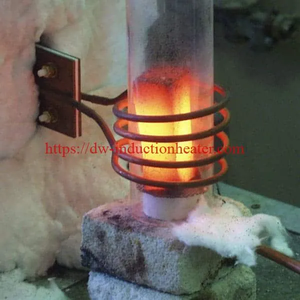
Induction heating graphite carbon works because graphite is electrically conductive, so the coil heats the part directly.
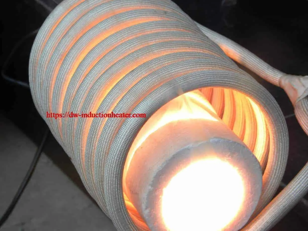
In this HLQ case, carbon graphite anodes measuring 2.5 × 2.5 × 4 in (63 × 63 × 102 mm) were heated to 1900 °F (1038 °C). The heating used a DW-MF-25KW induction heating system at 15 kHz and a custom multi-turn helical coil. Fresh air (~25 ft³/hr) swirled over the surface so that the anodes oxidized destructively and their embedded contaminants could be processed. After 2.5 hours, each anode had burned down to a piece about 0.375 in in diameter. A pyrometer/controller held the temperature constant throughout, making the process very efficient and controllable.

What is Induction Heating of Graphite Carbon?
An alternating current in the coil induces eddy currents in the graphite, which heat it directly. In the HLQ case below, this direct heating was used together with an air supply to oxidize carbon graphite anodes in a controlled way.
| Item | HLQ case data |
|---|---|
| Objective | Heat carbon graphite anodes to destructively oxidize the parts, so that the embedded contaminants can be processed |
| Material | Carbon graphite anodes, 2.5 × 2.5 × 4 in (63 × 63 × 102 mm), h × w × d |
| Temperature | 1900 °F (1038 °C) |
| Frequency | 15 kHz |
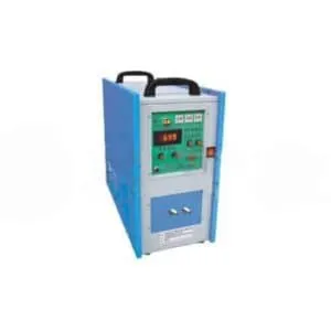
| Equipment | DW-MF-25KW induction heating system, custom multi-turn helical coil, workhead with 4 × 1.0 µF capacitors |
| Air purge | Fresh air, ~25 ft³/hr, with a swirling action for maximum contact with the anode surface |
| Cycle | After 2.5 hours, the anode burns down to a piece about 0.375 in in diameter |
| Control | Pyrometer/controller keeps the temperature constant as the anode shrinks |
| Result | Induction heating makes the process very efficient and controllable |
Key Applications

| Application | Role of graphite | HLQ reference |
|---|---|---|
| Destructive oxidation of carbon graphite anodes | The workpiece, heated directly | This case |
| Glass reflow for X-ray tubes | Graphite susceptor (950 °C, 80 kHz, DW-HF-25kW) | induction heating graphite susceptor |
| Heating non-conductive materials (ceramics, glass, plastics) | Susceptor that transfers heat | induction susceptor heating |
Suitable Materials
| Material | Notes |
|---|---|
| Carbon graphite anodes | Heated directly in this case |
| Graphite susceptors | Heated by induction, then heat the part by conduction or radiation |
| Other susceptor materials | Silicon carbide, molybdenum, stainless steels (HLQ susceptor article) |
Working Principle

- The DW-MF-25KW and its workhead (4 × 1.0 µF) drive the multi-turn helical coil at 15 kHz.
- Eddy currents heat the conductive graphite anode directly.
- Fresh air swirls over the hot anode surface and oxidizes the carbon.
- As the anode shrinks, the pyrometer/controller adjusts power to hold 1900 °F (1038 °C).
| Graphite resistivity (typical) | Skin depth at 15 kHz (calculation) |
|---|---|
| 8 µΩ·m | ≈ 11.6 mm |
| 10 µΩ·m | ≈ 13.0 mm |
| 15 µΩ·m | ≈ 15.9 mm |
Calculated with δ = 503·√(ρ/(µr·f)) and µr = 1. The 63 mm anode section is about 4–5 skin depths at 15 kHz; coupling falls as the anode shrinks. See skin effect in induction heating and how an induction heater works.
Technical Specifications
| Parameter | Value |
|---|---|
| Part size | 2.5 × 2.5 × 4 in (63 × 63 × 102 mm) |
| Process temperature | 1900 °F (1038 °C) |
| Frequency | 15 kHz |
| Power supply | DW-MF-25KW |
| Coil | Custom multi-turn helical |
| Workhead | 4 × 1.0 µF capacitors |
| Air purge | ~25 ft³/hr (≈ 0.71 m³/h) |
| Cycle time | 2.5 hours |
| End size | About 0.375 in (≈ 9.5 mm) diameter |
| Temperature control | Pyrometer/controller, constant temperature |

Recommended Model Selection
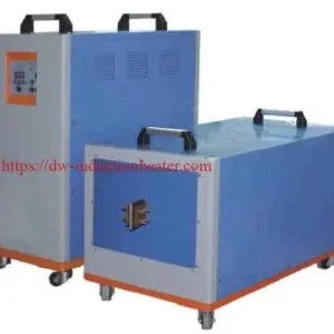
The graphite anode case used the DW-MF-25KW at 15 kHz. All DW-MF models work at 1–20 kHz on a 3-phase 380 V supply, with 100% duty cycle for long cycles such as the 2.5-hour oxidation.
| Model | Power | Input current | Frequency | Supply | Duty |
|---|---|---|---|---|---|
| DW-MF-15 | 15 kW | 23 A | 1–20 kHz | 3-ph 380 V | 100% |
| DW-MF-25 | 25 kW | 36 A | 1–20 kHz | 3-ph 380 V | 100% |
| DW-MF-35 | 35 kW | 51 A | 1–20 kHz | 3-ph 380 V | 100% |
| DW-MF-45 | 45 kW | 68 A | 1–20 kHz | 3-ph 380 V | 100% |
| DW-MF-70 | 70 kW | 105 A | 1–20 kHz | 3-ph 380 V | 100% |
| DW-MF-90 | 90 kW | 135 A | 1–20 kHz | 3-ph 380 V | 100% |
| DW-MF-110 | 110 kW | 170 A | 1–20 kHz | 3-ph 380 V | 100% |
| DW-MF-160 | 160 kW | 240 A | 1–20 kHz | 3-ph 380 V | 100% |
Larger anodes or shorter cycles call for a higher power rating. Details: DW-MF-25kW solid state induction heating power supply, medium frequency induction power generator, and HLQ induction heating device models.
Process Workflow

| Step | Action |
|---|---|
| 1 | Place the anode inside the helical coil |
| 2 | Start the air purge (~25 ft³/hr, swirling) |
| 3 | Heat the anode to 1900 °F (1038 °C) |
| 4 | Hold the temperature with the pyrometer/controller |
| 5 | Let the anode oxidize over 2.5 hours |
| 6 | Stop when a piece of about 0.375 in remains |
| 7 | Process the embedded contaminants |
Station layout

Common Problems and Solutions
| Problem | Cause | Solution |
|---|---|---|
| Temperature drops as the anode shrinks | Smaller part, weaker coupling | Closed-loop pyrometer/controller adjusts power (as in the case) |
| Slow or uneven oxidation | Too little fresh air at the surface | Air purge with a swirling action (~25 ft³/hr in the case) |
| Combustion gases in the work area | Oxidation products | Exhaust from the heating zone |
| Power supply overheats on long cycles | Duty cycle or cooling not suited to continuous work | 100%-duty DW-MF supply with water cooling |
Engineering Selection Guide
| Factor | What to confirm | Why it matters |
|---|---|---|
| Part size and grade | For example, 63 × 63 × 102 mm | Sets coil size and frequency |
| Temperature | For example, 1900 °F (1038 °C) | Sets power and control |
| Atmosphere | Air (oxidation) or protective gas | Graphite oxidizes in air at high temperature |
| Cycle time | For example, 2.5 hours | Continuous-duty rating |
| Temperature measurement | Pyrometer position and range | Constant temperature as the part changes |
Advantages and Limitations
| Advantages | Limitations |
|---|---|
| Graphite heats directly; no furnace chamber to heat | The coil is designed for each part size |
| Constant temperature under closed-loop control | Coupling changes as the part shrinks |
| Very efficient and controllable process (case result) | Air supply and exhaust are needed for oxidation |
| Visible, accessible heating zone | Long cycles need continuous-duty equipment and cooling |
Why Choose HLQ?
| Strength | Evidence |
|---|---|
| Graphite experience | Anode oxidation and graphite susceptor cases |
| Custom coils | Multi-turn helical coil designed for the anode |
| Closed-loop control | Pyrometer/controller holds 1900 °F |
| DW-MF series | 15–160 kW, 1–20 kHz, 100% duty |
| Susceptor heating | Heating non-conductive materials |
10 Core FAQs
1. Can graphite be heated by induction?
Yes. Graphite is electrically conductive, so it heats directly in the coil.
2. What was the goal of this case?
Destructive oxidation of carbon graphite anodes, so that the embedded contaminants could be processed.
3. What size were the anodes?
2.5 × 2.5 × 4 in (63 × 63 × 102 mm).
4. What temperature was used?
1900 °F (1038 °C).
5. Which equipment and frequency were used?
A DW-MF-25KW induction heating system at 15 kHz, with a workhead of 4 × 1.0 µF capacitors.
6. Which coil was used?
A custom multi-turn helical coil.
7. Why is air supplied?
Fresh air (~25 ft³/hr) feeds the oxidation, and the swirl gives maximum contact with the anode surface.
8. How long does the process take?
About 2.5 hours, until the anode is a piece about 0.375 in in diameter.
9. How is the temperature kept constant?
A pyrometer/controller adjusts the power as the anode shrinks.
10. What is needed for a quotation?
The part material and size, the temperature, the atmosphere or air flow, the cycle time, and the available supply.