


Semi-Automatic Induction Foging Rod Furnace
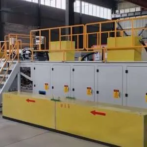
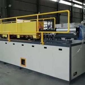
Semi-Automatic Induction Rod Forging Furnace with Pneumatic Feeding
Quick Answer: The HLQ Semi-Automatic Induction Rod Forging Furnace is a medium-frequency induction heating system designed to heat steel, copper, brass, bronze, and aluminum rods before hot forging, upsetting, heading, and other metal-forming operations.
Best-Fit Applications: Semi-automatic induction forging is particularly suitable for small- and medium-batch rod heating, rod-end upsetting, hot heading, valve and fitting production, forging workshops, and manufacturing cells that require pneumatic feeding without necessarily implementing a fully automated production line.
Engineering Selection: The appropriate furnace model depends on rod diameter, material grade, heated length, target forging temperature, heating time, production rate, induction coil design, and available electrical and cooling utilities. Actual production capacity must be confirmed for the selected workpiece and heating cycle.
Table of Contents
- What is the Semi-Automatic Induction Rod Forging Furnace?
- Key Applications
- Suitable Materials
- Working Principle
- Technical Specifications
- Recommended Model Selection
- Process Workflow
- Common Problems and Solutions
- Engineering Selection Guide
- Advantages and Limitations
- Why Choose HLQ?
- 10 Core FAQs
What is the Semi-Automatic Induction Rod Forging Furnace?
A semi-automatic induction rod forging furnace is an electrically powered industrial heating system that combines electromagnetic induction heating with a pneumatic rod handling mechanism. It is designed to heat cylindrical metal rods or selected rod sections to the temperature required for forging, upsetting, heading, or hot forming.
Unlike a manually loaded induction heater, a semi-automatic forging system incorporates a mechanical feeding mechanism to position or advance the rod through the heating station.
Unlike a fully automatic forging line, however, some operations may still require operator involvement. These may include loading, material selection, workpiece removal, or transfer to the forming machine, depending on the supplied configuration.
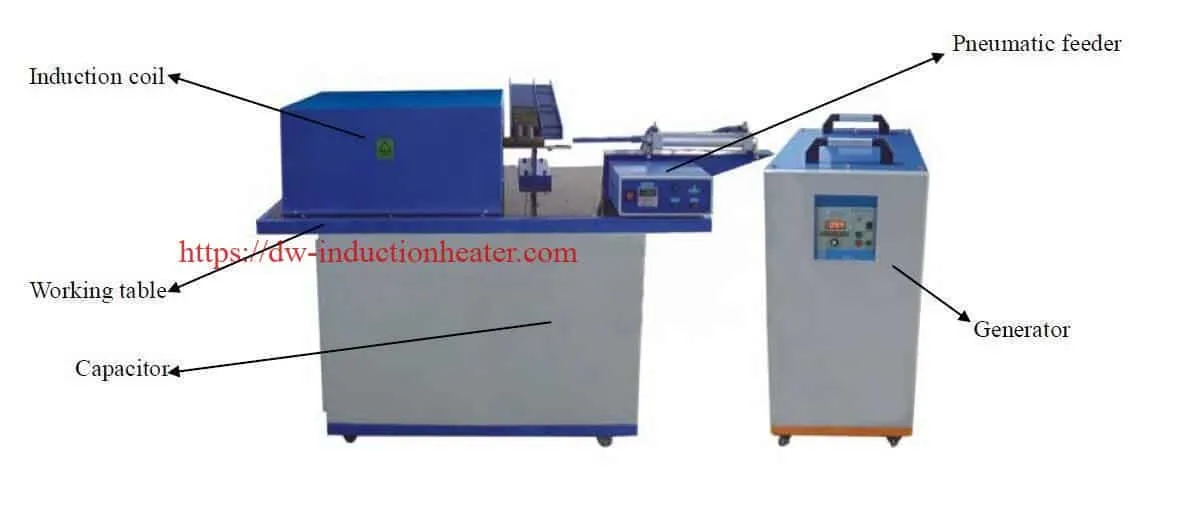
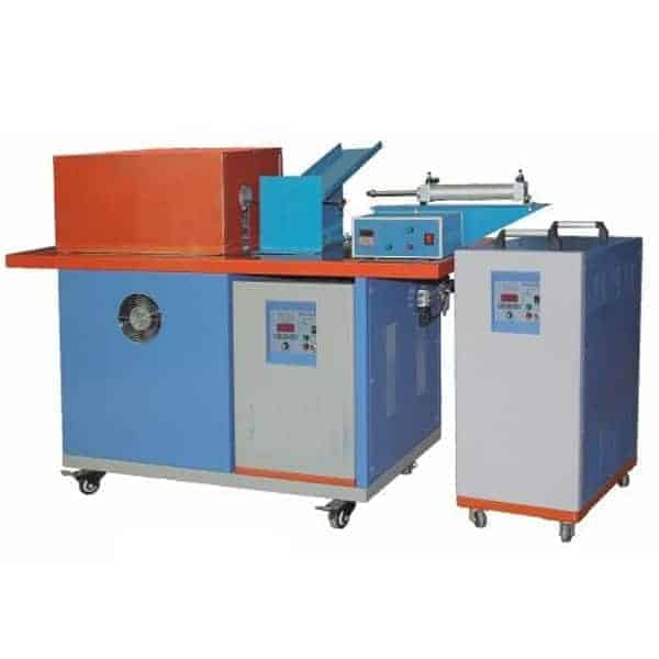
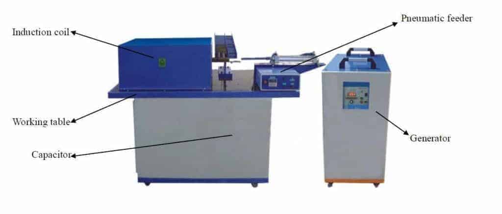
The principal components are a medium-frequency induction generator, compensation capacitor unit, induction heating coil, pneumatic rod feeder, and working table.
The system is suitable for manufacturing operations that require repeatable heating but do not necessarily need a complete unattended production line.
Main Components of the Semi-Automatic Forging Furnace
| Component | Function | Engineering Consideration |
|---|---|---|
| DW-MF Induction Generator | Supplies alternating electrical power to the induction heating system | Must match the workpiece and resonant load |
| Compensation Capacitor Unit | Forms part of the resonant electrical circuit | Must be compatible with the coil and inverter |
| Induction Heating Coil | Generates the electromagnetic field used to heat the rod | Selected according to rod diameter and heated length |
| Pneumatic Rod Feeder | Advances the workpiece into the heating area | Requires suitable compressed-air pressure and flow |
| Guide and Positioning System | Maintains workpiece alignment | Must accommodate the rod diameter and movement |
| Working Table | Supports the heating equipment and material handling system | Requires mechanical stability and suitable operating clearances |
| Cooling System | Removes waste heat from designated components | Must meet the specified cooling conditions |
| Control System | Coordinates heating and feeding operations | Control features depend on the equipment configuration |
Difference Between Manual, Semi-Automatic, and Fully Automatic Rod Heating
| Feature | Manual | Semi-Automatic | Fully Automatic |
|---|---|---|---|
| Material Loading | Operator-controlled | Manual or mechanically assisted, depending on configuration | Can be integrated with automatic storage and loading |
| Rod Advancement | Manual positioning | Pneumatic or mechanical assistance | Automatically controlled feeding sequence |
| Heating Cycle | Operator or timer controlled | Can be coordinated with the feeder | Can be integrated with production automation |
| Workpiece Discharge | Usually manual | Depends on the supplied handling system | Can be automatically coordinated |
| Production Flexibility | Suitable for frequent manual changes | Suitable for repeated batches and flexible production | Suitable for stable, repetitive high-volume operations |
| Automation Complexity | Low | Moderate | Higher |
| Typical Production Environment | Small workshop or testing | Small and medium forging cells | Integrated industrial production line |
For high-volume production and more comprehensive automatic handling, compare the full automatic induction rod forging furnace configuration.
Key Applications
The Semi-Automatic Induction Rod Forging Furnace can be used for industrial heating processes in which rods or bars must reach a specified forming temperature before mechanical deformation.
Applications vary according to the workpiece material, rod dimensions, heated section, and production requirements.
1. Steel Rod Hot Forging
Carbon steel rods can be heated before forging into machine components, industrial fittings, fasteners, and other metal products.
The induction heating system should provide a suitable temperature distribution across the required forming section.
2. Rod-End Upsetting
For rod-end upsetting, only a selected end region may need to reach the required forming temperature.
An appropriately designed induction coil can concentrate heating around the selected region while reducing unnecessary heating of the remaining rod.
3. Bolt and Fastener Manufacturing
Semi-automatic induction heating can be used before hot heading or upsetting operations in the production of selected bolts, fasteners, and threaded components.
Repeatable rod positioning helps maintain a consistent heating cycle.
4. Valve and Fitting Production
Steel, copper, and brass rods can be heated before hot forming into valves, fittings, connectors, and industrial hardware.
Forging temperatures must be selected according to the actual material grade.
5. Copper and Brass Rod Forging
Copper and brass rods require different electromagnetic and thermal design considerations from carbon steel.
The heating system must account for their electrical conductivity, thermal conductivity, and alloy-specific forging requirements.
6. Small-Batch Forging Production
Semi-automatic induction forging is useful where manufacturers process compatible rod sizes in repeated batches but require greater operational flexibility than a dedicated fully automatic production line.
| Application | Typical Material | Heating Objective | Primary Engineering Requirement |
|---|---|---|---|
| Steel Rod Forging | Carbon steel | Heat the required forming section | Suitable surface and core temperature |
| Rod-End Upsetting | Carbon and alloy steel | Localized end heating | Controlled heated length |
| Fastener Hot Heading | Steel | Prepare the rod end for deformation | Consistent cycle and positioning |
| Valve Production | Steel, brass, copper alloys | Heat material before forming | Alloy-specific temperature |
| Copper Rod Forging | Copper | Heat the selected forging region | Suitable electrical matching |
| Brass Fitting Manufacturing | Brass | Prepare rod sections for hot forming | Temperature and oxidation control |
| Industrial Hardware | Steel and compatible alloys | Localized or partial rod heating | Repeatable feeding and heating |
For industrial production requiring whole-bar heating rather than only localized forging, compare HLQ’s induction forging bar and billet furnace equipment.
Suitable Materials
Induction forging is applicable to electrically conductive materials, including steel, copper, brass, bronze, and selected aluminum alloys.
The required induction power, operating frequency, and heating time depend on the electromagnetic and thermal characteristics of the material.
Some materials change their magnetic properties significantly during heating. This is particularly important when designing induction heating systems for ferromagnetic steel.
| Material | Typical Application | Heating Characteristics | Engineering Requirement |
|---|---|---|---|
| Carbon Steel | Rods, bolts, fittings | Magnetic properties change with temperature | Account for the Curie transition and required core temperature |
| Alloy Steel | Machine components and shafts | Thermal properties vary with composition | Use grade-specific forging requirements |
| Stainless Steel | Specialized formed parts | Electromagnetic properties depend on grade | Verify actual stainless steel composition |
| Copper | Electrical and industrial fittings | High conductivity and thermal diffusivity | Optimize coil coupling and power delivery |
| Brass | Valves and connectors | Conductive copper-zinc alloy | Control temperature and zinc-related process risks |
| Bronze | Industrial hardware | Properties depend on alloy composition | Use alloy-specific process parameters |
| Aluminum Alloys | Lightweight components | Nonferromagnetic and highly conductive | Control temperature to avoid overheating or local melting |
Forging Temperature Reference
The temperature ranges below provide preliminary engineering context. They are not universal operating instructions or guaranteed values for the DW-MF equipment.
| Material | Indicative Temperature | Engineering Notes |
|---|---|---|
| Carbon Steel | Approximately 1050–1200°C | Depends on grade and forming operation |
| Alloy Steel | Approximately 950–1200°C | Use grade-specific forging limits |
| Stainless Steel | Grade-dependent | Temperature and holding requirements differ substantially |
| Copper | Approximately 650–900°C | Depends on copper grade and forming process |
| Brass | Composition-dependent | Consider zinc-containing fumes and overheating |
| Aluminum Alloys | Approximately 350–550°C | Requires alloy-specific temperature control |
Temperature Qualification: The original HLQ listing mentions heating capability up to 1350°C. This does not mean that every material should be heated to 1350°C or that every configuration is guaranteed to achieve this temperature under all loading conditions.
Working Principle
The Semi-Automatic Induction Rod Forging Furnace operates using electromagnetic induction and a pneumatic-assisted material handling system.
The DW-MF generator supplies alternating electrical current to the induction heating coil through its matching circuit.
The alternating current generates a changing magnetic field around the coil. When a conductive rod is positioned within the effective magnetic field, electrical currents are induced in the metal.
The resistance of the material converts the induced currents into heat. Heat then spreads through the rod by thermal conduction.
For ferromagnetic steel, electromagnetic properties change significantly during heating. The coil, frequency, power, and heating time should therefore be selected for the complete temperature cycle.
Main Induction Heating Components
| Step | Component | Function |
|---|---|---|
| 1 | Electrical Supply | Provides power to the induction generator |
| 2 | DW-MF Generator | Produces alternating current at the induction operating frequency |
| 3 | Compensation Capacitor | Supports the resonant matching circuit |
| 4 | Induction Heating Coil | Generates the changing magnetic field |
| 5 | Metal Rod | Absorbs electromagnetic energy and generates heat |
| 6 | Pneumatic Feeder | Advances the rod through the selected heating position |
| 7 | Control Equipment | Coordinates the heating and feeding sequence |
| 8 | Cooling System | Removes heat from designated electrical and coil components |
Induction Heating Frequency
The original HLQ product page publishes a medium-frequency operating range of 1–20 kHz.
It also refers to application-dependent operating frequencies around 4 kHz, 8 kHz, 11 kHz, 15 kHz, and 20 kHz.
These values should not be interpreted as fixed operating frequencies assigned to individual DW-MF models.
The selected frequency depends on the induction coil, rod dimensions, material properties, resonant matching, and required heating depth.
| Factor | Influence | Selection Consideration |
|---|---|---|
| Rod Diameter | Changes the thermal diffusion distance | Consider surface and core heating requirements |
| Material Grade | Changes resistivity and magnetic behavior | Use temperature-dependent material properties |
| Operating Frequency | Influences induced current distribution | Verify the loaded operating point |
| Coil Geometry | Changes field distribution and coupling | Match the workpiece and power supply |
| Heating Duration | Determines thermal conduction time | Validate the required core temperature |
| Power Density | Influences heating rate | Avoid excessive surface overheating |
Technical Specifications
HLQ lists five DW-MF induction generator models for this semi-automatic forging furnace.
The following table preserves the manufacturer-published electrical ratings while identifying the parameters that still require clarification.
DW-MF Model Specifications
| Parameter | DW-MF-45 | DW-MF-70 | DW-MF-90 | DW-MF-110 | DW-MF-160 |
|---|---|---|---|---|---|
| Published Maximum Input Power | 45 kW | 70 kW | 90 kW | 110 kW | 160 kW |
| Published Maximum Output Rating | 45 kVA | 70 kVA | 90 kVA | 110 kVA | 160 kVA |
| Input Voltage | 380 V ±10% | 380 V ±10% | 380 V ±10% | 380 V ±10% | 380 V ±10% |
| Input Phase | 3 Phase | 3 Phase | 3 Phase | 3 Phase | 3 Phase |
| Input Frequency | 50/60 Hz | 50/60 Hz | 50/60 Hz | 50/60 Hz | 50/60 Hz |
| Published Induction Frequency Range | 1–20 kHz | 1–20 kHz | 1–20 kHz | 1–20 kHz | 1–20 kHz |
| Pneumatic Rod Feeding | Listed | Listed | Listed | Listed | Listed |
| Rod Diameter Range | Confirm | Confirm | Confirm | Confirm | Confirm |
| Actual Production Capacity | Application-dependent | Application-dependent | Application-dependent | Application-dependent | Application-dependent |
| Cooling Water Requirements | Confirm | Confirm | Confirm | Confirm | Confirm |
Engineering Note: The original page uses kW for maximum input power and kVA for maximum output power. These values must not be treated as interchangeable. Actual input current, input apparent power, output power, and loaded electrical performance should be verified in the formal equipment specification.
General System Specifications
| Parameter | Specification | Engineering Notes |
|---|---|---|
| Equipment Type | Semi-Automatic Induction Rod Forging Furnace | Medium-frequency induction heating with assisted feeding |
| Power Supply Series | DW-MF | Five published power classes |
| Induction Frequency | 1–20 kHz | Actual operating frequency depends on load matching |
| Electrical Supply | Three-phase 380 V ±10%, 50/60 Hz | Confirm site compatibility |
| Material Feeding | Pneumatic Rod Feeder | Confirm assisted and automatic functions |
| Induction Coil | Application-Specific | Matched to rod diameter and heated length |
| Compensation Capacitor | Listed as a main component | Matched to the resonant circuit |
| Working Table | Listed as a main component | Mechanical arrangement depends on configuration |
| Published Operating Duty | 100%, 24-hour operation claimed | Verify cooling and operating conditions |
| Published Maximum Temperature Claim | Up to 1350°C | Not a universal guaranteed result |
| Temperature Monitoring | Configuration-dependent | Confirm sensor inclusion and accuracy requirements |
| Cooling Water Flow | Not fully published | Specify minimum flow and allowable temperature |
| Compressed-Air Requirements | Not fully published | Specify pressure, consumption, and air quality |
Pneumatic Feeder Engineering Parameters
The pneumatic feeding mechanism should be selected according to the workpiece dimensions, weight, surface condition, and desired cycle time.
| Parameter | Required Specification | Engineering Purpose |
|---|---|---|
| Rod Diameter | Minimum and maximum diameter | Determines guide and pusher dimensions |
| Rod Length | Minimum and maximum length | Determines supported feeding range |
| Rod Weight | Maximum kg per workpiece | Determines mechanical and pneumatic loading |
| Feeding Stroke | Required pusher travel | Determines cylinder arrangement |
| Feeding Cycle | Required movements per minute | Determines actuator speed |
| Compressed-Air Pressure | Manufacturer-specified operating range | Ensures adequate pneumatic force |
| Compressed-Air Consumption | Required flow per cycle or per minute | Allows compressor selection |
| Compressed-Air Quality | Filtration, moisture, and oil requirements | Protects pneumatic components |
| Rod Detection | Required sensor arrangement | Supports reliable feeding |
| Feeder Jam Protection | Required fault response | Reduces mechanical damage and downtime |
Recommended Model Selection
The correct induction forging furnace should be selected according to the actual heating requirements rather than only the rated power.
Rod diameter, heated length, material, starting temperature, forging temperature, and required production rate all influence equipment sizing.
For semi-automatic production, the mechanical feeder cycle and operator handling time must also be considered.
| Application | Material | Power Class to Evaluate | Frequency | Selection Note |
|---|---|---|---|---|
| Small Rod-End Heating | Carbon Steel | DW-MF-45 / DW-MF-70 | Within the published 1–20 kHz family range | Confirm heated length and pieces/hour |
| Medium Rod Forging | Carbon Steel | DW-MF-70 / DW-MF-90 | Application-specific | Verify workpiece mass and core temperature |
| Higher-Mass Rod Heating | Carbon and Alloy Steel | DW-MF-110 / DW-MF-160 | Application-specific | Confirm feeder capacity and heating time |
| Copper Rod Heating | Copper | Determine through engineering calculations | Load-specific | Account for high conductivity and heat transfer |
| Brass Fitting Production | Brass | Determine from mass and cycle time | Load-specific | Verify alloy-specific forging temperature |
| Aluminum Rod Hot Forming | Aluminum Alloy | Determine from alloy and production rate | Load-specific | Maintain a controlled forging temperature |
Selection Qualification: The model groups above are preliminary engineering candidates, not manufacturer-guaranteed diameter or throughput ratings. The original table does not clearly assign every published rod diameter range to all five DW-MF models.
Model Selection by Production Requirement
| Production Requirement | Primary Selection Factor | Engineering Consideration |
|---|---|---|
| Small Batch Production | Flexibility and operating convenience | Consider setup and coil-change time |
| Medium Batch Production | Heating cycle and feeder repeatability | Balance operator handling and heating time |
| Rod-End Upsetting | Localized heating length | Use an application-specific induction coil |
| Through-Heating | Core temperature and heating duration | Consider thermal diffusion through the rod |
| Multiple Rod Diameters | Interchangeable coils and feeder adjustments | Verify the actual changeover process |
| Continuous Multi-Shift Production | Duty, cooling, and reliability | Validate operating conditions and maintenance schedule |
Process Workflow
In a semi-automatic induction forging system, material preparation, pneumatic feeding, electromagnetic heating, and workpiece removal must be coordinated.
The actual division between operator actions and automatic functions depends on the installed feeder and control configuration.
Semi-Automatic Rod Heating Process
Process Sequence: Rod Inspection → Workpiece Loading → Rod Positioning → Pneumatic Feeding → Induction Heating → Temperature Verification → Workpiece Discharge → Hot Forging.
| Step | Operation | Process Objective | Quality or Safety Check |
|---|---|---|---|
| 1 | Rod Inspection | Confirm material and dimensions | Correct rod grade and condition |
| 2 | Workpiece Loading | Present the next rod to the feeding position | Safe and stable workpiece placement |
| 3 | Rod Positioning | Align the rod with the heating station | Correct guide and coil clearance |
| 4 | Pneumatic Feeding | Advance the rod through the heating zone | Correct stroke and no mechanical interference |
| 5 | Induction Heating | Heat the selected material region | Correct power and heating cycle |
| 6 | Temperature Verification | Confirm the required process temperature | Suitable calibrated measurement method |
| 7 | Workpiece Discharge | Remove or transfer the heated rod | Safe hot-material handling |
| 8 | Forging | Form the rod into the required component | Approved forming temperature and process timing |
| 9 | Quality Inspection | Verify the manufactured component | Dimensional and applicable metallurgical requirements |

Semi-Automatic Feeding Sequence
The pneumatic pusher advances the workpiece according to the selected feeding sequence.
For safe and reliable operation, the system should prevent feeding faults that could result in workpiece collisions, misalignment, or unexpected movement.
| Function | Purpose | Configuration Note |
|---|---|---|
| Rod-Present Detection | Confirms that a rod is ready for processing | Specify the required sensor |
| Feeding Permission | Prevents feeding when the heating station is unavailable | Define the control sequence |
| Pneumatic Stroke Control | Controls rod advancement | Match to rod length and feeding distance |
| Feeder Jam Detection | Identifies abnormal feeding conditions | Define fault and recovery procedures |
| Heating Permission | Allows heating only under acceptable conditions | Coordinate with electrical and cooling interlocks |
| Discharge Permission | Controls movement after heating | Confirm downstream availability |
| Emergency Stop | Stops hazardous equipment operation | Design for the complete production cell |
Induction Coil and Guide Design
The induction heating coil should be designed according to the rod diameter, effective heating length, operating frequency, and required temperature distribution.
Mechanical guides must keep the rod correctly positioned during the feeding operation.
| Parameter | Design Requirement | Engineering Consideration |
|---|---|---|
| Coil Inner Diameter | Matched to rod diameter | Allow appropriate operating clearance |
| Active Coil Length | Matched to heated length | Control axial temperature distribution |
| Number of Coil Turns | Application-specific | Match the resonant heating circuit |
| Operating Frequency | Within the approved loaded range | Match the rod and power supply |
| Rod Guide | Compatible with workpiece dimensions | Prevent misalignment |
| Workpiece Clearance | Allow thermal expansion and movement | Prevent contact with energized components |
| Cooling Water | Manufacturer-specified conditions | Protect the coil and electrical components |
| Mechanical Supports | Stable operating arrangement | Maintain repeatable positioning |
Common Problems and Solutions
The performance of a semi-automatic induction forging furnace may be affected by workpiece variation, pneumatic feeding problems, coil alignment, generator matching, and cooling conditions.
| Problem | Possible Cause | Recommended Solution |
|---|---|---|
| Slow Rod Heating | Insufficient useful power, excessive heated mass, or poor coupling | Verify power delivery, coil geometry, and process conditions |
| Insufficient Core Temperature | Inadequate heating time or thermal diffusion | Review heating cycle and verify internal temperature |
| Surface Overheating | Excessive local power density | Review frequency, power, and coil geometry |
| Uneven Heating | Incorrect coil positioning or rod misalignment | Inspect guides and coil-to-workpiece clearance |
| Pneumatic Feeder Jam | Incorrect rod dimensions or guide interference | Inspect workpieces, feeder guides, and pneumatic system |
| Inconsistent Feeding Stroke | Air pressure variation or actuator problem | Verify pneumatic supply and cylinder operation |
| Low Pneumatic Force | Insufficient pressure, leakage, or actuator fault | Check regulator settings, hoses, valves, and cylinders |
| Generator Instability | Electrical mismatch or changing load conditions | Verify connections and resonant matching |
| Cooling Alarm | Low coolant flow, blockage, or high inlet temperature | Stop heating and restore approved cooling conditions |
| Excessive Scale Formation | Excessive temperature or prolonged heating | Review the heating cycle and forging-temperature target |
| Temperature Variation Between Rods | Inconsistent positioning, material, or initial temperature | Improve feeding repeatability and temperature verification |
| Unexpected Equipment Shutdown | Electrical, cooling, or control fault | Record the fault and arrange qualified technical inspection |
Engineering Selection Guide
A suitable semi-automatic induction forging system should be selected according to the complete heating and material handling process.
1. Identify the Material Grade
Determine the material composition and required forging-temperature range.
Different alloys respond differently to induction heating because their electrical and thermal properties vary.
2. Confirm Rod Dimensions
Specify the minimum and maximum rod diameters, overall lengths, and effective heated lengths.
These values determine the required induction coil and feeder arrangement.
3. Calculate the Effective Heated Mass
For a solid cylindrical rod, the mass of the heated section can be estimated from:
m = ρ × π × d² × L / 4
Where:
- m = Effective heated mass, kg.
- ρ = Material density, kg/m³.
- d = Rod diameter, m.
- L = Heated length, m.
4. Estimate the Required Heating Energy
For a simplified sensible-heating calculation:
Q = m × Cp × ΔT
Where:
- Q = Theoretical useful thermal energy, kJ.
- m = Effective heated mass, kg.
- Cp = Approximate mean specific heat capacity, kJ/kg·K.
- ΔT = Temperature increase, K.
This simplified equation does not include heat losses, detailed temperature-dependent properties, or the effects of phase changes.
5. Engineering Calculation Example
Consider an illustrative carbon steel rod with a diameter of 25 mm and a heated length of 150 mm.
Assume the rod is heated from 25°C to 1100°C.
For preliminary calculations, use a density of 7850 kg/m³ and a mean specific heat capacity of 0.65 kJ/kg·K.
| Parameter | Value | Data Status |
|---|---|---|
| Material | Carbon Steel | Illustrative example |
| Rod Diameter | 25 mm | Assumed |
| Heated Length | 150 mm | Assumed |
| Steel Density | 7850 kg/m³ | Approximate reference value |
| Effective Heated Mass | 0.578 kg | Calculated |
| Initial Temperature | 25°C | Assumed |
| Target Temperature | 1100°C | Assumed |
| Temperature Increase | 1075 K | Calculated |
| Mean Specific Heat | 0.65 kJ/kg·K | Approximate assumption |
| Theoretical Heating Energy | Approximately 404 kJ | Calculated |
| Equivalent Thermal Energy | Approximately 0.112 kWh | Calculated |
If the target production rate is 60 rods per hour, the average useful thermal power is approximately 6.7 kW.
For illustration only, assuming an overall electrical-to-workpiece heating efficiency of 50%, the corresponding average electrical input would be approximately 13.5 kW.
Important: These values are theoretical estimates and do not represent guaranteed heating performance of any DW-MF model. Actual electrical power depends on coil matching, generator losses, thermal losses, production cycle, and operating conditions.
6. Rod Diameter and Heating Energy
For the same heated length and temperature increase, the theoretical energy requirement increases with the square of rod diameter.
| Rod Diameter | Heated Length | Approximate Heated Mass | Theoretical Heating Energy |
|---|---|---|---|
| 15 mm | 150 mm | 0.208 kg | 0.040 kWh |
| 20 mm | 150 mm | 0.370 kg | 0.072 kWh |
| 25 mm | 150 mm | 0.578 kg | 0.112 kWh |
| 30 mm | 150 mm | 0.832 kg | 0.162 kWh |
| 35 mm | 150 mm | 1.133 kg | 0.220 kWh |
| 40 mm | 150 mm | 1.480 kg | 0.287 kWh |
The table assumes carbon steel heated from 25°C to 1100°C using the same simplified thermal properties.
It does not include furnace losses, electrical losses, or differences in heating time.
7. Calculate the Required Production Capacity
The mass throughput can be estimated using:
Mass Throughput = Rod Weight × Pieces per Hour
For example, heating 60 rods per hour, each with an effective heated mass of 0.578 kg, represents approximately 34.7 kg of heated metal per hour.
Actual electrical sizing must also account for the required heating time and operating efficiency.
8. Match the Induction Power Supply and Coil
Choose a generator and coil arrangement according to the required heating load.
The operating frequency should be selected according to the material, diameter, coil geometry, and heating duration.
The induction coil must be electrically compatible with the generator and resonant matching circuit.
9. Confirm the Semi-Automatic Feeder
Verify the rod diameter range, rod length, maximum rod weight, pusher stroke, feeding cycle, and compressed-air requirements.
Define which operations are performed automatically and which require operator intervention.
10. Conduct an Application Test
Representative testing should verify heating time, surface and core temperatures, actual power consumption, feeding reliability, and production capacity.
The test should use the same material and workpiece geometry intended for production.
| Test Item | Verification | Acceptance Basis |
|---|---|---|
| Workpiece Compatibility | Process representative rod sizes | Approved rod diameter and length range |
| Feeding Operation | Test repeated pneumatic feeding cycles | Stable operation without unacceptable jamming |
| Heating Time | Record actual heating duration | Agreed production cycle |
| Surface Temperature | Use an appropriate calibrated measurement method | Specified temperature range |
| Core Temperature | Verify where required by the forging process | Specified cross-sectional temperature requirement |
| Electrical Input | Measure input power or energy | Approved electrical limits |
| Operating Frequency | Record loaded frequency | Approved operating range |
| Cooling Performance | Measure flow and coolant temperature | Specified cooling requirements |
| Pneumatic Operation | Verify pressure and feeding cycle | Approved actuator performance |
| Production Capacity | Record accepted rods over a defined period | Required pieces/hour or kg/hour |
Advantages and Limitations
Advantages of Semi-Automatic Induction Forging
Semi-automatic induction forging equipment can offer a useful balance between manual production flexibility and mechanized material handling.
| Advantage | Engineering Benefit |
|---|---|
| Pneumatic Feeding | Reduces repetitive manual rod advancement |
| Flexible Production | Suitable for repeated small and medium batches |
| Localized Heating | Allows selected rod sections to be heated |
| Adjustable Heating Power | Supports different heating requirements |
| Compact Production Cell | Can be installed near suitable forging equipment |
| Reduced Burner Dependence | Does not require direct fuel combustion at the heating station |
| Interchangeable Coil Potential | Allows the system to be adapted to compatible rod sizes |
| Process Repeatability | Supports consistent feeding and heating under controlled conditions |
Limitations and Engineering Considerations
| Limitation | Engineering Consideration |
|---|---|
| Operator Involvement | Some loading or unloading operations may remain manual |
| Rod Size Restrictions | The feeder and coil must match the workpiece |
| Compressed-Air Requirements | Pneumatic operation requires adequate air pressure and quality |
| Electrical Matching | The induction coil must be compatible with the generator |
| Cooling Dependency | High-current components require reliable cooling |
| Surface and Core Temperature Differences | Large rods may require longer heating or different frequency selection |
| Production Capacity | Depends on heating time and operator handling |
| Equipment Changeover | Different rod sizes may require coil or feeder adjustment |
| Process Validation | Critical forging applications require representative testing |

Why Choose HLQ?
HLQ Induction Equipment Co., Ltd. provides industrial induction heating systems for forging, brazing, hardening, annealing, melting, and other metalworking applications.
The semi-automatic rod forging furnace combines a DW-MF power supply with a pneumatic feeding mechanism for suitable industrial production requirements.
Application-Based Equipment Selection
Equipment selection can be based on the rod material, dimensions, heating temperature, production rate, and available factory utilities.
DW-MF Medium-Frequency Power Supply
The published product family includes five DW-MF power classes from 45 kW to 160 kW.
The correct electrical configuration should be selected according to the workpiece and application requirements.
Pneumatic Rod Feeding
The integrated pneumatic handling arrangement can assist workpiece advancement through the heating station.
The final feeding sequence and operating scope should be confirmed for the selected configuration.
Application-Specific Induction Coils
Different workpiece dimensions and heating zones may require different induction coil designs.
Coil selection should consider electrical matching, mechanical clearance, cooling, and temperature distribution.
Flexible Manufacturing Integration
Depending on the application, the semi-automatic forging furnace may be installed beside a suitable mechanical or hydraulic forging machine.
Production integration should include safe workpiece handling and a coordinated operating sequence.
For higher-power through-heating and larger billet applications, explore HLQ’s induction billet heaters for hot forming steel, copper, and aluminum.
For nonferrous billet and rod heating, see the induction aluminum billet and rod heating furnace.
10 Core FAQs
1. What is a semi-automatic induction forging rod furnace?
A semi-automatic induction forging rod furnace combines an induction heating system with a mechanically assisted feeding arrangement, usually involving a pneumatic pusher. It is designed to heat metal rods before forging, upsetting, heading, or other hot-forming operations.
2. Which DW-MF models are available?
HLQ lists DW-MF-45, DW-MF-70, DW-MF-90, DW-MF-110, and DW-MF-160 models. Their published maximum input power values are 45 kW, 70 kW, 90 kW, 110 kW, and 160 kW, respectively.
3. What operating induction frequency does the furnace use?
The published frequency range is 1–20 kHz. The actual operating frequency depends on the selected induction coil, workpiece dimensions, material properties, and electrical matching arrangement.
4. What is the difference between semi-automatic and fully automatic induction forging?
A semi-automatic system provides mechanical assistance for selected feeding or heating operations, while other operations may require operator involvement. A fully automatic line can integrate loading, feeding, heating, temperature monitoring, and discharge according to the supplied automation configuration.
5. Can the furnace heat steel, copper, brass, and aluminum rods?
Yes. These electrically conductive materials can be heated by induction when the coil, power supply, operating frequency, and heating process are correctly designed. Each material requires appropriate temperature and power selection.
6. What is the maximum rod diameter?
The maximum rod diameter depends on the selected model, material, heating length, temperature, and production requirements. The original published table does not clearly assign every rod-size range to all five models, so the exact capacity must be confirmed.
7. Does the pneumatic feeder require compressed air?
Yes. The pneumatic feeding mechanism requires a suitable compressed-air supply. The required pressure, air consumption, filtration, moisture control, and actuator specifications should be confirmed for the selected system.
8. Can the furnace heat only the end of a rod?
Yes. A suitably designed induction coil can heat a selected rod-end section for upsetting or localized forging. The required heated length, temperature distribution, and cycle time determine the coil configuration.
9. Can the furnace operate continuously?
The original product page claims 100% duty and 24-hour operation. Actual continuous-duty capability depends on the equipment configuration, cooling system, ambient conditions, maintenance, and production cycle. These requirements should be verified before installation.
10. How is the required induction forging power calculated?
The required power depends on the effective heated mass, temperature increase, material properties, heating time, and system losses. A preliminary calculation can use Q = m × Cp × ΔT, but final equipment sizing requires evaluation of electromagnetic coupling, electrical losses, cooling, and the actual production cycle.
Related products
-
Induction Billet Heater
-
Induction Aluminum Billet Heating Furnace For Aluminum Extrusion and Forging
-
Induction Billet Heating Furnace For Rolling Mills and Extrusion Metals Billets Bars rods
-
Continuous Steel Billet Heater with Induction Heating For Forging Steel Copper Aluminum Metals
-
Aluminium Billet Induction Heater for Extrusion Energy Efficient Metals Heating Solution