

Induction Melting Furnace With Tilting Device
Tilting Induction Melting Furnace for Steel, Copper, Aluminum and Precious Metals
What Is the Tilting Induction Melting Furnace?
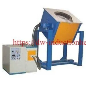
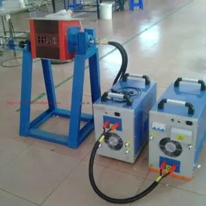
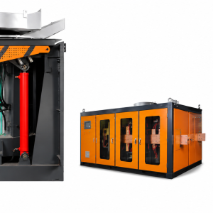
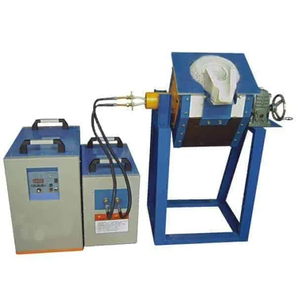
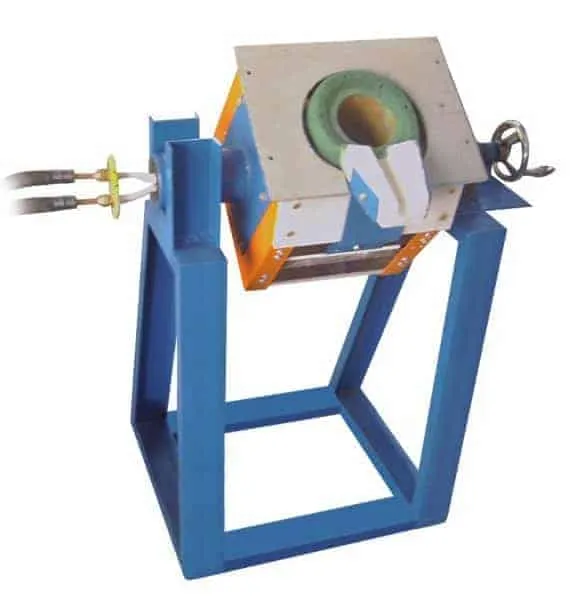
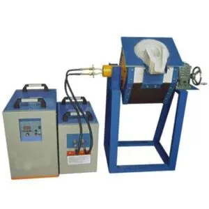
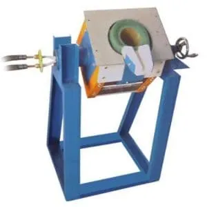
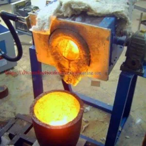
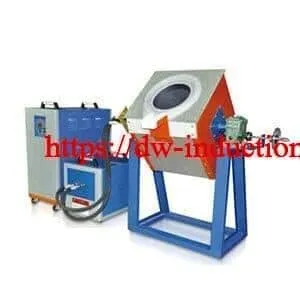
The HLQ DW-MF Tilting Induction Melting Furnace is a medium-frequency electric melting system combining an induction power supply, a resonant compensation circuit, a water-cooled induction coil and a furnace body that can be tilted to discharge molten metal into a suitable ladle or mold. The published series comprises eight models, DW-MF-15 through DW-MF-160, with stated maximum input-power ratings of 15–160kW, a series operating-frequency range of 1–20kHz, and three-phase 380V ±10%, 50/60Hz electrical supply. The best-fit applications are batch melting and controlled pouring of suitably prepared steel, stainless steel, aluminum, copper alloys and precious metals. Furnace size, crucible construction, actual melting rate and tilting mechanism must be confirmed for each ordered configuration.
Quick Engineering Answer
| Question | Direct Answer |
|---|---|
| What makes the furnace different? | The furnace body tilts for pouring; the induction circuit provides heat without fuel combustion inside the melt chamber. |
| Published model range | DW-MF-15, 25, 35, 45, 70, 90, 110 and 160. |
| Published maximum input power | 15–160kW; not guaranteed sustained power delivered into the metal. |
| Published supply and frequency | Three-phase 380V ±10%, 50/60Hz; 1–20kHz series range. |
| Published main assembly | MF power generator, tilting furnace and compensation capacitor. |
| Primary selection data | Metal, batch mass, target temperature, required tap-to-tap cycle, crucible, site electricity, cooling and pouring arrangement. |
When evaluating different generator technologies, compare HLQ
industrial induction heating power supplies
before finalizing the melting system.
Key Applications
Tilting is valuable when a batch furnace must transfer molten metal repeatedly and predictably. Pouring geometry and operator separation are as important as electrical melting speed.
| Application | Typical Charge | Why Tilting Matters | Acceptance Criterion |
|---|---|---|---|
| Precision steel casting | Clean carbon steel or alloy-steel returns | Directs high-temperature melt into a prepared ladle | Pouring temperature, metal yield, safe tilt and lining integrity |
| Stainless-steel foundry work | Identified stainless grades and master alloys | Supports controlled alloy transfer | Temperature, alloy composition and slag practice |
| Aluminum remelting | Ingots, runners, cast returns and clean scrap | Facilitates repeated ladle or mold charging | Hydrogen/oxide control, temperature and dross loss |
| Copper and brass casting | Clean copper, bronze or segregated brass | Helps transfer molten nonferrous metal | Correct crucible, controlled temperature and fume management |
| Jewelry alloy production | Gold, silver and specified precious-metal alloys | Allows small-batch, repeatable pouring | Recovery rate, contamination and alloy identity |
| Research and specialty alloys | Well-characterized experimental charges | Enables batch-by-batch process comparison | Documented temperature, chemistry and batch traceability |
For higher-temperature ferrous-foundry design requirements, see HLQ’s
induction furnace for melting iron and steel.
Tilting vs. Fixed Crucible Configurations
| Selection Factor | Tilting Furnace | Fixed or Removable Crucible Arrangement |
|---|---|---|
| Molten-metal transfer | Furnace body changes angle to pour | Requires compatible ladle or crucible-handling method |
| Key mechanical design | Trunnions, drive, stops, center of gravity and pouring lip | Lifting access, crucible handling and thermal shielding |
| Primary safety question | Can full-load pouring be controlled and stopped safely? | Can molten crucibles be handled without spill or fracture? |
| Best purchasing metric | Demonstrated melting and controlled pouring | Demonstrated melting and validated transfer procedure |
Suitable Materials
The same induction generator may be offered for different metals, but the crucible, refractory, coil coupling, thermal control and ventilation must match the actual alloy. Treat published batch masses as configuration-specific references rather than interchangeable capacities.
| Metal or Alloy | Approximate Melting-Point Reference | Major Engineering Issue | Required Verification |
|---|---|---|---|
| Carbon steel | Typically about 1425–1540°C, composition dependent | High lining temperature, slag and metal breakout hazards | Steel-grade tap temperature, refractory compatibility and pouring procedure |
| Stainless steel | Broadly about 1370–1530°C, grade dependent | Alloy control and chromium-bearing slag | Grade chemistry, refractory and melt-sampling method |
| Cast iron | Composition-dependent solidus/liquidus, often below steel | Carbon/silicon control and lining wear | Charge recipe, treatment and intended casting grade |
| Copper | Pure copper approximately 1085°C | High conductivity; melt oxidation | Coil/crucible coupling, oxygen control and pouring temperature |
| Brass and bronze | Strongly alloy dependent | Zinc fume for brass; alloy loss if overheated | Alloy grade, ventilation, chemical analysis |
| Aluminum | Pure aluminum approximately 660°C | Oxide film, contamination and melt treatment | Alloy solidus/liquidus and melt-cleaning practice |
| Gold and silver | Pure gold about 1064°C; pure silver about 962°C | Purity, crucible contamination and metal recovery | Precious-alloy recipe and recovery accounting |
| Magnesium and reactive alloys | Alloy dependent | Special ignition, fire and atmosphere hazards | Dedicated engineered system; not assumed suitable for a standard open furnace |
For copper-specific furnace designs, see HLQ
copper induction melting furnace systems.
Crucible and Refractory Selection
| Charge Type | Typical Design Consideration | Why a Trial Is Needed |
|---|---|---|
| Ferrous melting | Appropriate high-temperature refractory lining | Chemical attack, thermal cycling and lining wear vary with slag and alloy. |
| Nonferrous conductive crucible | Graphite or graphite-containing crucible where alloy-compatible | The crucible may itself couple electromagnetically and become a major heating element. |
| Nonconductive crucible | Ceramic compatible with metal and temperature | Heat is induced mainly in the charge once coupling is established. |
| Precious-metal batch | Low-contamination crucible and controlled pouring lip | Recoverable metal yield and product chemistry are critical. |
Working Principle
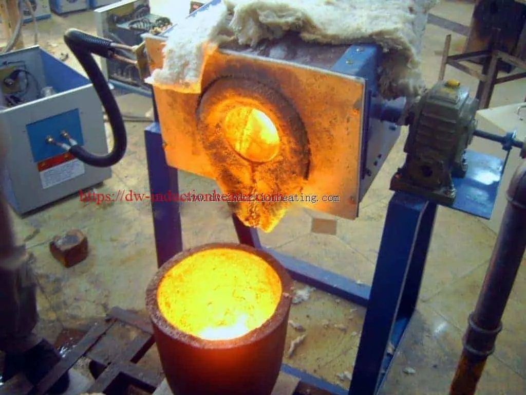
The MF generator produces alternating current at an operating frequency compatible with the load and compensation network. Current in the water-cooled copper coil produces a changing magnetic field. In a conductive metal charge, induced eddy currents generate resistive heat. In some crucible systems, the conductive crucible is also heated directly and passes heat into the charge. As molten metal forms, electromagnetic forces may help circulate the bath. Controlled tilting is a separate mechanical operation performed only after safe melting and temperature verification.
Figure 1. Electrical Heating and Tilting-Pour Principle
 THREE-PHASE AC INPUT (380V NOMINAL)
                 |
                 v
       +-------------------+
       | DW-MF GENERATOR   |
       | POWER CONTROL     |
       +-------------------+
                 |
                 v
       +-------------------+
       | MATCHING /        |
       | CAPACITOR CIRCUIT |
       +-------------------+
                 |
                 v
       +-------------------+
       | WATER-COOLED      |
       | INDUCTION COIL    |
       +-------------------+
                 |
        CHANGING MAGNETIC FIELD
                 |
                 v
       +-------------------+
       | CRUCIBLE + METAL  |
       | EDDY-CURRENT HEAT |
       +-------------------+
                 |
                 v
        MELT / TEMPERATURE CHECK
                 |
                 v
      TILTING DEVICE -> LADLE / MOLD

 Cooling and safety interlocks protect
 the electrical and melting systems.

How Electromagnetic and Mechanical Systems Interact
| Subsystem | Operating Principle | Measurement to Record |
|---|---|---|
| Power converter | Supplies controlled medium-frequency coil power | True electrical input kW, line current, operating frequency |
| Induction coil | Creates the alternating magnetic field | Coil current, water flow and return temperature |
| Crucible/charge | Converts induced electrical energy into heat | Metal temperature, charge mass, alloy chemistry |
| Molten bath | Possible electromagnetic circulation and thermal mixing | Temperature uniformity and slag behavior |
| Tilting mechanism | Rotates furnace about a supported axis | Tilt angle, drive stability, stops and pouring rate |
Figure 2. Furnace Cross-Section (Conceptual)
             MELT / SLAG SURFACE
          +-----------------------+
          |      MOLTEN METAL     |
          |   electromagnetic     |
          |       circulation     |
          |                       |
          |     CRUCIBLE /        |
          |    REFRACTORY LINING  |
   (((((  +-----------------------+  )))))
   (((((     WATER-COOLED COIL       )))))
          +-----------------------+
             INSULATED FURNACE BODY
                TILTING TRUNNION
                     O
                    /  -> POURING DIRECTION
Technical Specifications
The following rows distinguish the original published ratings from engineering details that the current product page does not establish. The published 70–550V line is labeled “input voltage,” although the same page states a three-phase 380V supply. This must be clarified before procurement and should not be presented as a valid mains supply range.
General Technical Parameters
| Parameter | Specification | Notes |
|---|---|---|
| Product | DW-MF Tilting Induction Melting Furnace | Eight models on the reviewed page |
| Maximum listed input power | 15–160kW | Model-dependent maximum input rating; sustained real power to verify |
| Factory supply | Three-phase 380V ±10%, 50/60Hz | Published electrical supply |
| Additional voltage entry | 70–550V, labeled “Input voltage” | Meaning inconsistent/unclear; verify whether it denotes output/load range |
| Published oscillation frequency | 1–20kHz series range | Examples given: approximately 4, 8, 11, 15 and 20kHz |
| Duty-cycle claim | 100%, described as 24-hour operation | Requires specified ambient, cooling and rated load; not independently tested here |
| Published melting-time reference | 30–50min cold furnace; 20–30min subsequently | Not defined for every metal/model/charge combination |
| Furnace components listed | MF generator, tilting furnace, compensation capacitor | Confirm whether cooling plant, crucible and controls are included |
| Tilting drive | Not stated | Confirm manual, geared electric, hydraulic or other drive |
| Semiconductor type | Product categorized as IGBT tilting furnace | Confirm actual inverter topology for each offered configuration |
| Water flow/pressure | Not published on product page | Specify generator, capacitor and furnace branches |
| Tap-to-tap guarantee | Not independently established | Require charge-specific FAT data |
Published Power and Weight Entries
| Model | Published Max. Input Power | Published Weight (Assembly Not Specified) | Operating Frequency |
|---|---|---|---|
| DW-MF-15 | 15kW | 50kg | 1–20kHz series range; actual load point to verify |
| DW-MF-25 | 25kW | 50kg | As above |
| DW-MF-35 | 35kW | 65kg | As above |
| DW-MF-45 | 45kW | 70kg | As above |
| DW-MF-70 | 70kW | 80kg | As above |
| DW-MF-90 | 90kW | 94kg | As above |
| DW-MF-110 | 110kW | 114kg | As above |
| DW-MF-160 | 160kW | 145kg | As above |
The published cabinet-dimension row is incomplete for the eight individual models. Request model-specific outline drawings before designing foundations, lifting points or access clearances.
Published Maximum Melting Capacity by Metal
| Model | Steel / Stainless Steel | Gold / Silver | Aluminum |
|---|---|---|---|
| DW-MF-15 | Not listed | 5kg or 10kg | 3kg |
| DW-MF-25 | 4kg or 8kg | 10kg or 20kg | 6kg |
| DW-MF-35 | 10kg or 14kg | 20kg or 30kg | 12kg |
| DW-MF-45 | 18kg or 22kg | 40kg or 50kg | 21kg |
| DW-MF-70 | 28kg | 60kg or 80kg | 30kg |
| DW-MF-90 | 50kg | 80kg or 100kg | 40kg |
| DW-MF-110 | 75kg | 100kg or 150kg | 50kg |
| DW-MF-160 | 100kg | 150kg or 250kg | 75kg |
Interpretation: Alternative values such as “4kg or 8kg” are reproduced from the published table; they are not two guaranteed capacities for a single universal crucible. Confirm which crucible and lining correspond to each option. The steel entry for DW-MF-15 is blank in the source and must not be interpreted as a tested zero or positive capacity.
Figure 3. Published Melting Capacity Comparison
                        STEEL (kg)     ALUMINUM (kg)

 DW-MF-25                4 or 8        6
 DW-MF-35               10 or 14      12
 DW-MF-45               18 or 22      21
 DW-MF-70               28            30
 DW-MF-90               50            40
 DW-MF-110              75            50
 DW-MF-160             100            75

 Chart compares published batch capacities only,
 not kg/h production rates.
Recommended Model Selection
Start with the required charge and metal, not just a target kW figure. The model suggestions below reference the published capacity table and must be followed by a sample or factory melting test. A single generator series frequency range is not proof that every crucible and metal operates satisfactorily at every frequency.
| Application | Material | Recommended Power | Frequency |
|---|---|---|---|
| Small jewelry batches, 5–10kg published class | Gold / silver | DW-MF-15, 15kW maximum input | Confirm loaded operating point within published 1–20kHz series |
| Small steel batch, 4kg or 8kg published class | Steel / stainless steel | DW-MF-25, 25kW maximum input | Coil and charge-specific; request measured frequency |
| Small aluminum casting batch, 12kg published class | Aluminum | DW-MF-35, 35kW maximum input | Confirm crucible coupling and matched resonance |
| Small steel foundry, 18kg or 22kg published class | Steel / stainless steel | DW-MF-45, 45kW maximum input | Match high-temperature furnace coil |
| Medium nonferrous batch, 30kg published class | Aluminum | DW-MF-70, 70kW maximum input | Load-dependent; verify under melting conditions |
| Ferrous foundry batch, 50kg published class | Steel / stainless steel | DW-MF-90, 90kW maximum input | Check cold and molten resonant conditions |
| Ferrous foundry batch, 75kg published class | Steel / stainless steel | DW-MF-110, 110kW maximum input | Confirm measured operating frequency |
| Larger batch, 100kg steel or 75kg aluminum listed | Steel / aluminum with different crucibles | DW-MF-160, 160kW maximum input | Confirm configuration-specific matching |
For dedicated aluminum scrap and foundry applications, compare HLQ’s
tilting aluminum induction melting furnace.
Model Approval Checklist
| Required Confirmation | Why It Matters | Requested Supplier Evidence |
|---|---|---|
| Exact crucible capacity | Determines usable batch weight and freeboard | Crucible drawing and actual metal-specific capacity |
| Real input power at full load | Controls energy/time calculation | True three-phase kW measurement and power trace |
| Operating frequency | Defines resonant compatibility | Measured frequency at cold and molten conditions |
| Tilting drive and pouring reach | Determines ladle integration and mechanical safety | Tilting drawings, rated load and functional test |
| Cooling and utilities | Protects coil, inverter and capacitor equipment | Flow, pressure, heat rejection and water quality specification |
| Process acceptance | Converts a capacity claim into real production evidence | Repeatable weighed batches, kWh/t and tap-to-tap time |
Process Workflow
Figure 4. Batch Melting, Controlled Tilting and Pouring
 VERIFY ALLOY / CHARGE MASS / DRYNESS
                  |
                  v
 INSPECT REFRACTORY, TILT SYSTEM, COOLING
                  |
                  v
 CHARGE APPROVED MATERIAL
                  |
                  v
 START MF INDUCTION HEATING
                  |
                  v
 MELT + ADJUST CHEMISTRY + MANAGE SLAG
                  |
                  v
 MEASURE MOLTEN-METAL TEMPERATURE
                  |
                  v
 READY-TO-POUR SAFETY CHECK
                  |
                  v
 TILT GRADUALLY INTO PREHEATED, DRY LADLE
                  |
                  v
 RETURN FURNACE TO HOME POSITION
                  |
                  v
 LOG BATCH MASS / kWh / TIME / QUALITY
Process Control and Inspection Points
| Stage | Operator or Control Action | Release Criterion |
|---|---|---|
| Incoming charge | Check chemistry, dryness, geometry and contaminants | No wet, sealed or otherwise prohibited charge |
| Pre-start | Check coil water, electrical interlocks, lining and tilt device | All safety and operating checks passed |
| Melting | Track input kW, frequency, current and bath formation | No abnormal trip, leak or overtemperature |
| Superheat and analysis | Measure temperature; take sample if process requires it | Target temperature/chemistry achieved |
| Tilting | Confirm dry ladle, clear exclusion zone and pour path | Controlled flow without splash or tilt instability |
| Batch closeout | Log electricity, recover metal, inspect slag and lining | Recorded yield, quality and maintenance state |
Coil and Fixture Design
A tilting melting furnace requires an integrated electromagnetic, thermal and mechanical design. Unlike a solid-billet induction coil, its load changes from irregular cold charge pieces to a molten pool; both the coil impedance and the heat-transfer path can change significantly.
Induction Coil, Furnace Body and Tilting Mechanism
| Component | Engineering Requirement | Critical Failure Mode |
|---|---|---|
| Water-cooled copper coil | Appropriate copper section, turns, cooling flow, turn insulation and mechanical support | Overheating, short circuit, water leak |
| Compensation capacitor | Electrical matching for coil and load across cold/hot cycle | Excessive reactive current, overheating or inverter trip |
| Crucible | Metal-compatible material, capacity, wall thickness and freeboard | Cracking, chemical contamination, leakage |
| Refractory/insulation | Compatible with liquid metal, slag and thermal cycling | Erosion, metal breakout, coil damage |
| Furnace support and trunnion | Rated center of gravity across full tilt travel | Mechanical instability or uncontrolled motion |
| Pouring lip and ladle position | Predictable stream, adequate reach and splash protection | Spillage and operator exposure |
| Hoses and power cables | Safe flexible routing through all tilt positions | Hose abrasion, cable strain or contact with hot surfaces |
| Stops, lock and guarding | Safe tilt limits and personnel separation | Overtravel or unintended pouring |
Tilting Device Acceptance Checklist
| Test | What to Verify | Basis for Approval |
|---|---|---|
| No-load function | Smooth travel, angle limits and emergency stop | Approved factory procedure |
| Rated loaded tilt | Mechanical stability and controlled motion | Full-mass rated operating test under safe conditions |
| Power-loss behavior | Safe holding or controlled return | Documented drive/brake design |
| Pouring alignment | Stream reaches intended preheated ladle | Factory/site demonstration |
| Flexible services | No pinch, pull, heat or abrasion through full travel | Inspection at all positions |
Cooling-Water Engineering
For water near ordinary industrial temperatures:
Q(kW) ≈ 1.163 × Flow(m³/h) × Water Temperature Rise(°C).
This calculates heat carried by water; it does not state the chiller size without knowing measured losses, pump pressure and acceptable supply temperature.
| Illustrative Flow | Temperature Rise | Water-Side Heat Removal | Design Note |
|---|---|---|---|
| 5m³/h | 5°C | 29.1kW | Calculated example only |
| 10m³/h | 5°C | 58.2kW | Flow must be distributed to critical branches |
| 15m³/h | 5°C | 87.2kW | Verify pump pressure and real heat rejection |
| 20m³/h | 5°C | 116.3kW | Not a published DW-MF water requirement |
For molten-metal systems, never bypass a coil-water interlock to resume heating. Emergency procedures must be designed so electrical isolation and required residual cooling are coordinated safely.
Control System and Automation
The current product page does not provide a complete controller specification, PLC I/O map or tilting-drive type. Treat the features below as recommended controls or quotation items, not a statement that every DW-MF model includes them as standard.
| Control Function | Engineering Purpose | Supply Status / Verification |
|---|---|---|
| Real-power measurement | Distinguish true input kW from nameplate maximum | Request measured three-phase kW and kWh display |
| Operating-frequency monitoring | Confirm matching across melting cycle | Obtain actual range under load |
| Overcurrent / overvoltage protection | Protect inverter and capacitor network | Confirm trip thresholds and test sequence |
| Branch cooling-flow interlocks | Protect generator, coil and capacitors | Verify water flow, pressure and temperature alarms |
| Melt temperature instrument | Prevent over-temperature and ensure casting repeatability | Choose alloy-appropriate immersion or infrared method |
| Tilting interlock | Restrict movement to approved safe conditions | Confirm travel limit, emergency stop and drive hold |
| PLC/HMI recipe and batch log | Record metal, charge, power, temperature and cycle | Optional unless specified in purchase order |
| Safety stop and restart logic | Establish safe response to power or cooling failure | Require documented hazard assessment |
Batch Data Recommended for Quality Control
| KPI | Unit | Why It Matters |
|---|---|---|
| Gross and net charge mass | kg | Energy baseline and yield calculation |
| Measured input electricity | kWh | Specific consumption and utility cost |
| Energized melting time | min | Power utilization |
| Complete tap-to-tap time | min | True foundry throughput |
| Pouring temperature | °C | Casting consistency |
| Metal yield | % | Dross, slag and recovery performance |
| Cooling water supply/return | °C, m³/h | Equipment reliability |
Common Problems and Solutions
| Problem | Possible Cause | Engineering Solution |
|---|---|---|
| Melting time longer than advertised | Lower average kW, unsuitable charge or cold furnace | Record true input kW, kWh, charge and complete cycle |
| Power falls during melting | Resonant mismatch as metal shape and temperature change | Check capacitor/coil design and power trace with qualified personnel |
| Coil overheating | Insufficient branch flow, scale or excessive current | Stop heating safely; test cooling passage and electrical load |
| Frequent inverter trips | Coil fault, capacitor fault, electrical supply disturbance | Use manufacturer diagnostic procedure after isolation |
| Crucible cracks prematurely | Thermal shock, incompatible chemistry or improper drying | Follow crucible heat-up and inspection procedure |
| Molten metal too hot | Excess power/holding time or inaccurate temperature reading | Validate instrument and reduce unnecessary superheat |
| Poor molten-metal yield | Oxidation, slag, spills or unsuitable scrap | Optimize charge preparation, temperature and pouring practice |
| Metal stream misses ladle | Incorrect tilt geometry or ladle location | Rework pouring reach and position; repeat dry functional tests |
| Jerky tilting / drift | Drive, brake, mechanical support or control fault | Stop use and inspect by competent maintenance personnel |
| Water alarm while furnace is hot | Pump/flow fault, leak or sensor issue | Follow documented emergency isolation and cooling procedure |
| Contaminated precious-metal batch | Wrong crucible or mixed charge handling | Dedicated tools, segregated material and assay controls |
| Hazardous smoke during brass melting | Overtemperature and zinc-bearing fumes | Control temperature and provide engineered extraction |
Engineering Selection Guide
A melting-furnace quotation should distinguish nominal charge capacity, electrical maximum input power, specific electrical consumption, energized melt time and tap-to-tap time. These are different quantities.
1. Estimate Specific Melting Energy
The useful heat needed by a charge depends on material enthalpy, initial temperature, target tapping temperature and phase change. Additional electrical energy covers coil and inverter losses, heat escaping through furnace surfaces, warm-up and holding. For preliminary calculations only, the following broad planning assumptions may be used; they are not measurements of this DW-MF series.
| Material | Illustrative Planning Consumption | Main Sensitivities | Use |
|---|---|---|---|
| Steel / stainless steel | 650–950kWh per tonne | Cold start, refractory, target superheat, furnace utilization | Preliminary electrical energy scenarios only |
| Aluminum | 350–550kWh per tonne | Thin scrap, oxide/dross, holding and melt temperature | Preliminary scenarios only |
| Copper and copper alloys | 350–600kWh per tonne | Charge cleanliness, crucible coupling, oxidation, size | Preliminary scenarios only |
| Gold / silver | No DW-MF-specific value published | Small-batch heat losses and crucible choice dominate | Obtain factory sample melting data |
Formula: E(kWh) = Charge(t) × Assumed or measured specific consumption(kWh/t).
For 100kg steel at an illustrative 800kWh/t:
E = 0.10 × 800 = 80kWh.
2. Estimate Heating Time from Real Input Power
Idealized energized time (minutes) = 60 × E(kWh) / Mean measured real input power(kW).
This simplified expression requires an energy estimate with consistent system boundaries. A nameplate maximum is not evidence that the generator sustains that power throughout melting.
| Illustrative Scenario | Assumed Total Energy | Assumed Mean Real Input | Energy-Only Time |
|---|---|---|---|
| 8kg steel, 800kWh/t | 6.4kWh | 25kW | 15.4min |
| 28kg steel, 800kWh/t | 22.4kWh | 70kW | 19.2min |
| 100kg steel, 800kWh/t | 80.0kWh | 160kW | 30.0min |
| 50kg aluminum, 450kWh/t | 22.5kWh | 110kW | 12.3min |
| 75kg aluminum, 450kWh/t | 33.75kWh | 160kW | 12.7min |
These are hypothetical calculations, not model guarantees. They use assumed full mean power and illustrative kWh/t, exclude separate handling delays, and do not confirm that the published crucible/model combination can achieve the calculated cycle.
Figure 5. Energy-Only Time for 100kg Steel
 ASSUMED ENERGY 80kWh
 ILLUSTRATIVE MEAN INPUT POWER

   80kW   |##############################| 60 min

  100kW   |########################      | 48 min

  120kW   |####################          | 40 min

  160kW   |###############               | 30 min

 A real process includes temperature checks,
 chemistry, slag and pouring.
3. Calculate Actual Tap-to-Tap Productivity
Gross batch throughput (kg/h) = 60 × Nominal charge weight(kg) / Tap-to-tap time(min).
Good-metal output is lower if dross, slag or rejected material reduces yield.
| Charge | Illustrative Tap-to-Tap | Gross Throughput | At 95% Accepted-Metal Yield |
|---|---|---|---|
| 25kg | 40min | 37.5kg/h | 35.6kg/h |
| 50kg | 45min | 66.7kg/h | 63.3kg/h |
| 75kg | 50min | 90.0kg/h | 85.5kg/h |
| 100kg | 60min | 100.0kg/h | 95.0kg/h |
All productivity entries above are arithmetic examples, not independently verified HLQ production rates. Melting time is only one part of the full cycle.
4. Check Electrical Infrastructure
For a balanced three-phase line:
S(kVA) = 1.732 × Line Voltage(V) × Line Current(A) / 1000.
True input power is no greater than apparent power, and actual transformer sizing requires measured power factor, harmonics, losses, starting behavior and applicable electrical standards.
| Illustrative True Input | Assumed Power Factor | Calculated Apparent Power | Use |
|---|---|---|---|
| 25kW | 0.90 | 27.8kVA | Minimum simple electrical estimate; not a transformer selection |
| 70kW | 0.90 | 77.8kVA | Allow for supply and harmonic study |
| 110kW | 0.90 | 122.2kVA | Confirm system PF and input current |
| 160kW | 0.90 | 177.8kVA | Confirm cables, protective devices and supply transformer |
These are illustrative calculations using assumed real input and PF = 0.90; actual DW-MF electrical values must be measured or certified by HLQ.
5. Define Factory Acceptance Tests
| FAT Item | Required Evidence | Pass Basis |
|---|---|---|
| Exact scope | Generator, compensation cabinet, crucible, furnace body, tilt system and cooling | Signed bill of supply |
| Electrical performance | Measured input kW/kWh, voltage, current, frequency, PF | Agreed test conditions |
| Metal and charge | Weighed charge, grade, initial temperature and crucible type | Representative customer material |
| Melting results | Energy consumed, melt time, tapping temperature, chemistry | Agreed performance tolerance |
| Tilting performance | Loaded tilt, travel limits, holding behavior and controlled pouring | Safe functional demonstration |
| Cooling and interlocks | Water flows, pressures, temperatures and alarm tests | Equipment safety requirements |
| Repeatability | Multiple consecutive representative melts | Signed customer test protocol |
Advantages
| Potential Advantage | Engineering Value | Qualification |
|---|---|---|
| Electromagnetic heat generation | Heat is generated in conductive metal or compatible crucible | Efficiency depends on matching and charge design |
| Tilting pour arrangement | Can improve control over molten-metal discharge | Requires appropriate drive, geometry and operator protection |
| Electrical power adjustment | Supports different stages of melting and superheating | Actual turndown range must be verified |
| Range of published models | Eight input-power classes from 15 to 160kW | Charge ratings are metal-specific |
| Repeatable batch records | Enables comparison of kWh/t, yield and temperature | Requires measurement and logging instrumentation |
| Potential electromagnetic stirring | Can help molten-bath mixing | Flow pattern varies with furnace construction |
Limitations
| Limitation | Engineering Impact | Recommended Response |
|---|---|---|
| Published melting time is generic | Does not define every metal, charge, model or temperature | Request material-specific FAT results |
| Ambiguous 70–550V field | Unclear whether voltage is input, output or other | Obtain corrected electrical datasheet |
| Tilting drive unspecified | Cannot design ladle location and safety without it | Request mechanism drawings and load rating |
| Crucible material not universal | Alloy contamination or premature failure possible | Qualify crucible for each metal |
| Water-cooled equipment | Flow failures can damage coil and electronics | Interlocks, maintenance and emergency cooling plan |
| High-temperature metal hazards | Spill, moisture and refractory failure may be severe | Trained staff, exclusion zones, dry charge and validated procedures |
| Small-batch losses | Useful heat can be a small fraction of measured electricity | Measure actual kWh/batch and reduce idle holding |
| Reactive metals require specialization | Magnesium and similar charges create additional fire risk | Use purpose-engineered process and atmosphere |
Why Choose HLQ Induction Equipment?
HLQ offers medium-frequency induction equipment and related melting solutions for industrial metalworking. The practical value of a tilting system comes from correctly matching the generator, capacitors, crucible, refractory protection, cooling and mechanical pouring layout to a specified metal and production schedule. Buyers should request a model-specific drawing, a complete scope of supply, demonstrated melting performance and documented tilt-safety tests rather than relying on a single capacity figure.
For small precious-metal casting and workshop applications, compare HLQ’s
induction gold melting furnace solutions.
Technical RFQ Checklist
| Customer Requirement | Data to Supply |
|---|---|
| Metal and alloy | Exact grade, charge condition and contamination restrictions |
| Batch size | Net kilograms per melt; expected metal yield |
| Productivity | Desired melts/h, kg/h and shift length |
| Temperature | Charge temperature and tapping/pouring setpoint |
| Crucible | Required material, freeboard and expected replacement practice |
| Pouring equipment | Ladle/mold geometry, height, location and pouring rate |
| Electrical service | Line voltage, Hz, transformer kVA and plant protection requirements |
| Cooling | Available water quality, supply temperature, pressure and flow |
| Automation | Manual vs. controller operation, batch traceability and interlocks |
| Acceptance | Maximum kWh/t, qualified tap-to-tap time, tilt and safety tests |
Core FAQs
1. What is a tilting induction melting furnace?
It is an induction furnace that melts conductive metal and uses a tilting mechanism to pour molten metal into a suitable ladle or mold. The HLQ DW-MF page lists eight 15–160kW medium-frequency models and a tilting furnace assembly.
2. Which DW-MF models and input powers are available?
The published series comprises DW-MF-15, 25, 35, 45, 70, 90, 110 and 160, with corresponding listed maximum input-power values of 15, 25, 35, 45, 70, 90, 110 and 160kW. A rated maximum does not establish measured average melting power.
3. What metals can the DW-MF tilting furnace melt?
The product page lists steel, stainless steel, copper alloys, aluminum, gold and silver. The correct crucible, refractory, atmosphere, ventilation and process settings depend on the metal. Magnesium and other reactive charges require specialized design and must not be assumed compatible with an ordinary open-furnace package.
4. How much steel can a DW-MF-160 furnace melt?
The published reference table lists up to 100kg of steel or stainless steel for DW-MF-160. This is a batch-capacity reference, not a guaranteed melting rate or proof of a particular 20–30 minute cycle. Confirm crucible and melt trial conditions.
5. How long does one induction melting batch take?
The HLQ page mentions 30–50 minutes for a cold furnace and about 20–30 minutes for later hot-furnace melts. These generic descriptions do not specify the exact metal, full charge mass, tapping temperature or sustained input power. Use measured kWh and the complete tap-to-tap time to qualify production.
6. Does this furnace use hydraulic, electric or manual tilting?
The reviewed page states that a tilting device is supplied but does not define its driving method. Before ordering, confirm the exact tilting actuator, rated loaded travel, brake or holding arrangement, limit stops and the position of the receiving ladle.
7. What cooling system is required for a tilting induction furnace?
Induction generator components, compensation capacitors and water-cooled coil may all require cooling. Size the cooling plant using the manufacturer’s branch flow and pressure requirements and measured heat rejection. Do not select a chiller merely as a fixed percentage of furnace input kW.
8. What data should be included in the factory acceptance test?
A useful FAT includes actual alloy and charge weight, crucible, measured input electricity, operating frequency, melt temperature, energized time, complete tap-to-tap time, accepted-metal yield, cooling parameters and safe loaded-tilt/pouring demonstration. Repeat the process over multiple representative batches.