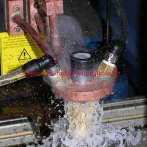


Induction Hardening
Induction Hardening Treatment for Steel Surfaces
Quick Answer
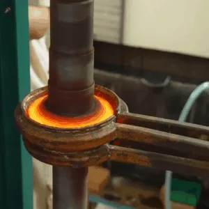
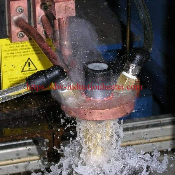
Induction hardening treatment heats the surface of a steel part above 723 °C (the austenitic temperature) by electromagnetic induction, then cools it quickly, often with a quench of industrial water. This transforms the structure of the steel and increases its hardness, yield strength and breaking tension, while the core stays tough.
The heat is generated inside the part, without contact, so the treatment is localized, rapid and economical. It is favored for heavily loaded parts such as axles, shafts, gears, spindles, saw blades and stampings. The steels normally hardened by induction contain 0.3% to 0.7% carbon.
What is Induction Hardening Treatment?
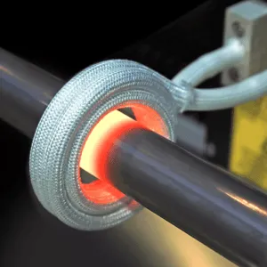
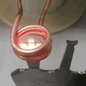
Induction hardening is a metal heat treatment process that heats a part in a controlled, localized way without touching it. An electric current is induced to flow in the part itself, so heat is generated only where it is needed. This makes it a very economical, targeted and rapid way to heat treat conductive materials.
It is widely used for surface hardening steel. The steel is heated above 723 °C and quenched quickly to transform its structure, which increases its hardness, yield strength and breaking tension.
| Item | Induction hardening treatment |
|---|---|
| Heating | Above 723 °C (austenitic temperature); non-contact, localized |
| Cooling | Rapid quench, often with industrial water |
| Result | Higher hardness, yield strength and breaking tension |
| Typical steels | 0.3%–0.7% carbon |
| Typical parts | Axles, saw blades, shafts, stampings, spindles, gears and most symmetrical parts |
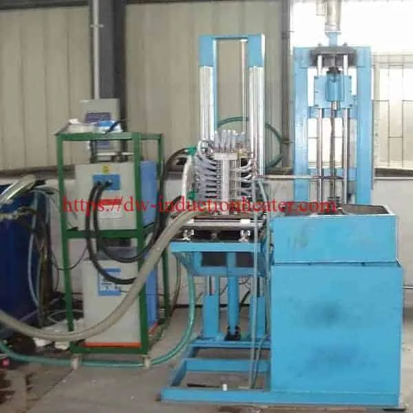
Key Applications

| Part group | Induction hardening treatment of… |
|---|---|
| Engine parts | Valves, crankshafts, camshafts, connecting rods and starter rings |
| Transmission parts | CV joints, tulips and axle shafts |
| Suspension parts | Shock absorber rods, springs and suspension arms |
| Gearbox parts (automatic and manual) | Rings, selector shafts and sun gears |
| Clutch and brake | Clutch springs and brake pads |
| General heavy-load parts | Axles, saw blades, shafts, stampings, spindles, gears |
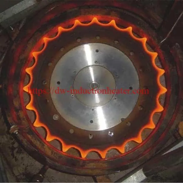
Gear hardening: gear hardening machine for gear tooth and surface hardening and tooth-by-tooth gear hardening. Shafts, rollers and pins: CNC vertical induction quenching machines.

Suitable Materials
| Material type | Typical grades | Suitability |
|---|---|---|
| Medium-carbon steel | 45 steel, C45, 1045, 50 steel | Very suitable |
| Alloy steel | 40Cr, 42CrMo, 4140, 4340 | Very suitable; deeper case depth |
| Carburizing steel | 20CrMnTi, 8620, 18CrNiMo7-6 | Conditionally suitable |
| Ductile iron | QT500, QT600 | Possible; needs process testing |
| Martensitic stainless steel | 410, 420 | Special application |
| Low-carbon steel | Q235, 1018 | Not ideal directly; carbon usually too low |
| Powder metal, cast iron | — | Listed on the original page; confirm by test |
| Copper, aluminum | — | Can be induction heated, but do not harden by quenching like steel |
Grade data from HLQ’s 15 key FAQs about induction hardening machines.
Working Principle

- The power supply drives an alternating current through the coil.
- Eddy currents heat a surface layer of the steel above 723 °C (austenite).
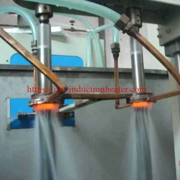
- A quench right behind the coil cools the layer rapidly, which forms the hardened case.
- The core is not heated and stays tough.
| Frequency | Skin depth in hot steel (calculation) |
|---|---|
| 1 kHz | ≈ 17 mm |
| 10 kHz | ≈ 5.5 mm |
| 30 kHz | ≈ 3.2 mm |
| 100 kHz | ≈ 1.7 mm |
| 200 kHz | ≈ 1.2 mm |
| 500 kHz | ≈ 0.8 mm |
Calculated with δ = 503·√(ρ/(µr·f)), using ρ ≈ 1.2×10⁻⁶ Ω·m and µr = 1 (steel above the Curie point). Higher frequency gives a shallower heated layer; lower frequency gives a deeper case. See skin effect in induction heating.
Technical Specifications
| Material | Typical surface hardness after induction hardening | Common application |
|---|---|---|
| 45 steel / C45 / 1045 | HRC 50–58 | Shafts, sprockets, pins |
| 40Cr / 5140 | HRC 52–60 | Gears, shafts, transmission parts |
| 42CrMo / 4140 | HRC 50–60 | Heavy-duty shafts, rollers, gears |
| Bearing steel | HRC 58–64 | Bearing races, precision parts |
| Ductile iron | HRC 45–55 | Rollers, guide parts, wear surfaces |
| Required case depth | Typical frequency range | Typical workpieces |
|---|---|---|
| 0.5–1.5 mm | High frequency | Small pins, small shafts, light gears |
| 1.5–3 mm | Super-audio frequency | Medium gears, sprockets, shafts |
| 3–6 mm | Medium frequency | Large shafts, rollers, heavy gears |
| 6–10 mm | Low-medium frequency | Large rollers, mining parts, large shafts |
Values are typical ranges from HLQ’s induction hardening FAQ article; actual results depend on grade and process.
Recommended Model Selection
Coil, power and frequency guide
| Application | Material | Recommended power | Frequency |
|---|---|---|---|
| Small pin and small shaft | 45 steel, 1045, 40Cr | 20–60 kW | 30–150 kHz |
| Medium shaft scanning | 45 steel, 40Cr, 4140 | 60–160 kW | 8–50 kHz |
| Heavy shaft, excavator pin | 42CrMo, 4140, 4340 | 160–400 kW | 1–20 kHz |
| Small gear spin hardening | 40Cr, 42CrMo, 1045 | 50–150 kW | 20–100 kHz |
| Large gear tooth-by-tooth | 42CrMo, 50Mn, alloy steel | 100–500 kW | 3–30 kHz |
| Bearing race | GCr15, 52100 | 80–300 kW | 5–50 kHz |
| Camshaft / crankshaft profile | Alloy steel, ductile iron | 100–350 kW | 3–30 kHz |
Source: induction hardening coil for steel surface hardening.
HLQ power supply series
| Series | Power | Frequency |
|---|---|---|
| DW-UHF | 4.5–60 kW | From 50 kHz up to 2.0 MHz, depending on model |
| DW-HF | 15–160 kVA | DW-HF-15KW: 30–100 kHz; 25–160 kVA: 20–80 kHz (model table) |
| DW-MF | 15–160 kW | 1–20 kHz |
Complete machines: induction hardening machine. All models: HLQ induction heating device models.
Process Workflow

| Stage | What happens | Key control parameter |
|---|---|---|
| Loading | Part clamped on a fixture or machine spindle | Alignment, runout, clamping force |
| Heating | Surface heated above 723 °C by induced current | Power, frequency, coil gap, heating time |
| Quenching | Heated layer cooled rapidly, often with industrial water | Flow rate, pressure, medium concentration |
| Tempering | Brittleness reduced after hardening | Temperature and holding time |
| Inspection | Hardness and case depth checked | HRC, case depth, microstructure, cracks |
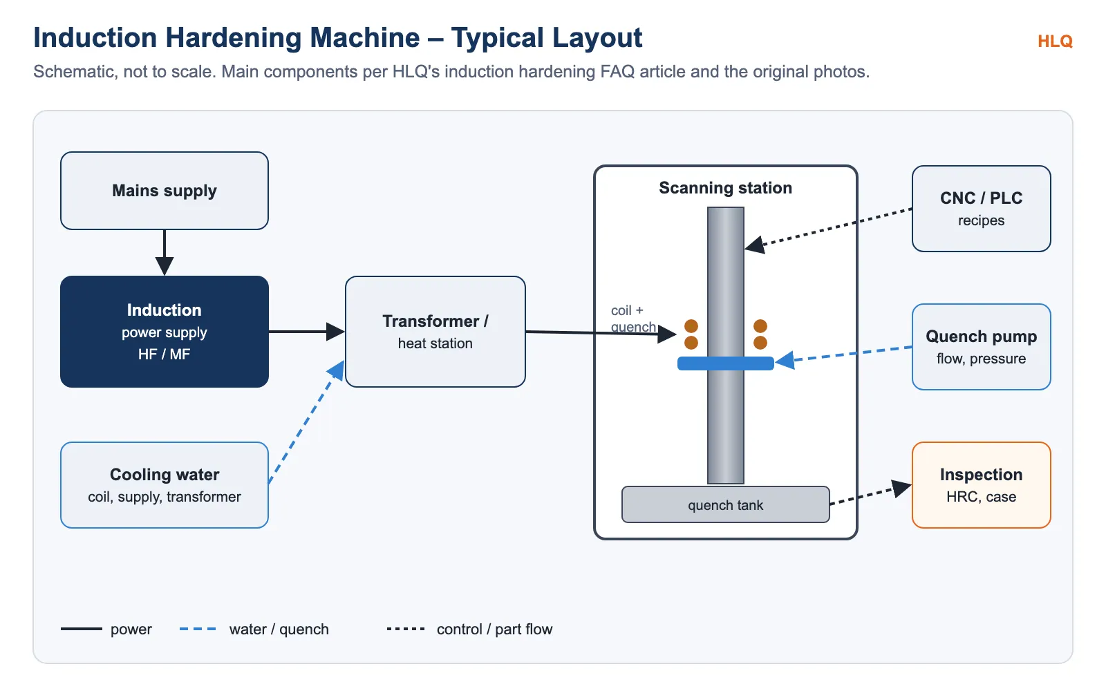
Machine layout

Common Problems and Solutions
| Problem | Possible cause | Solution |
|---|---|---|
| Uneven hardness around circumference | Runout, uneven coil gap, unstable rotation | Improve fixture concentricity, adjust coil position, stabilize rotation |
| Case depth too shallow | Frequency too high, power too low, heating too short, scan too fast | Lower frequency, more power, slower scan or longer heating |
| Case depth too deep | Frequency too low, heating too long, power density too high | Raise frequency, reduce power, shorten heating time |
| Soft spots | Poor coil coverage, wrong quench timing, uneven spray, dirty surface | Redesign coil pattern, adjust quench delay, clean spray holes and surface |
| Overheating at edges or shoulders | Field concentration at sharp geometry | Modify coil shape, increase local gap, add flux concentrator |
| Cracking after quenching | Excessive temperature, aggressive quench, high carbon, sharp corners | Reduce temperature, adjust quench medium, add tempering, improve radii |
Engineering Selection Guide
| Factor | What to confirm | Why it matters |
|---|---|---|
| Material grade | Carbon content (0.3–0.7% typical) | Achievable hardness |
| Hardened zone | Journal, tooth, bore, face, full length | Coil type: scanning, single-shot, profile, internal |
| Case depth | For example, 0.5–1.5 mm or 3–6 mm | Frequency |
| Hardness | Required HRC | Quench and tempering |
| Part size and output | Diameter, length, parts per hour | Power rating and automation |
| Utilities | Supply voltage; cooling water | Installation |
Advantages and Limitations
| Advantages | Limitations |
|---|---|
| Controllable, localized heating without contact | Coil designed for each part geometry |
| Economical, targeted and rapid | Steel needs enough carbon (typically 0.3–0.7%) |
| Hard surface with a tough core | Sharp corners and edges can overheat or crack |
| Higher hardness, yield strength and breaking tension | Quenching and tempering must be controlled |
More: induction hardening for surface hardness and wear resistance.
Why Choose HLQ?
| Strength | Evidence |
|---|---|
| Automotive hardening solutions | Engine, transmission, suspension, gearbox, clutch and brake parts |
| Full frequency range | DW-UHF, DW-HF and DW-MF series |
| Custom coils | Scanning, single-shot, profile and internal coils |
| Complete machines | Scanning, gear and CNC quenching machines |
| Process know-how | Hardness, case depth and quench control |
10 Core FAQs
1. What is induction hardening treatment?
A heat treatment that heats the steel surface by induction above 723 °C and quenches it quickly to raise hardness, yield strength and breaking tension.
2. Why is it called surface hardening?
Only a surface layer is heated and transformed; the core stays tough.
3. Which steels can be induction hardened?
Steels with 0.3% to 0.7% carbon, such as 1045, 40Cr, 4140 and 4340.
4. What quench is used?
The part is cooled quickly, often with a quench of industrial water.
5. How hard does the surface get?
Typically HRC 50–58 for 1045, HRC 52–60 for 40Cr, and HRC 58–64 for bearing steel.
6. How is case depth controlled?
Mainly by frequency: high frequency for about 0.5–1.5 mm, medium frequency for about 3–6 mm.
7. Which parts are induction hardened?
Axles, shafts, gears, spindles, saw blades, stampings, crankshafts, camshafts, CV joints, shock absorber rods and gearbox parts.
8. Can copper or aluminum be induction hardened?
They can be induction heated, but they do not harden by quenching the way steel does.
9. Is tempering needed after hardening?
Yes. Tempering reduces brittleness after hardening.
10. What is needed for a quotation?
The part drawing and material grade, the hardened zone, the required hardness and case depth, the parts per hour, and the available supply.