

Induction Hardening Cast Iron
Induction Hardening Cast Iron: Ductile Iron Pulleys to 55 HRC
Quick Answer
Induction hardening cast iron means heating the iron part with an induction coil to hardening temperature and quenching it immediately. In this HLQ case, ductile iron pulleys measuring 3 1/2″ (88.9 mm) OD and 2″ (50.8 mm) high were heated to 1600 °F (871.1 °C) in 2 minutes 45 seconds by a four-turn helical coil at 164 kHz. The power source was a DW-UHF-10kW induction heating system with a remote workhead containing eight capacitors totaling 0.66 µF. Each pulley was then quenched in an agitated water bath to reach 55 Rockwell C. Induction heating gave increased production, precise heating, and repeatable, non-contact, energy-efficient heat.
Table of Contents
- What is Induction Hardening of Cast Iron?
- Key Applications
- Suitable Materials
- Working Principle
- Technical Specifications
- Recommended Model Selection
- Process Workflow
- Common Problems and Solutions
- Engineering Selection Guide
- Advantages and Limitations
- Why Choose HLQ?
- 10 Core FAQs
What is Induction Hardening of Cast Iron?
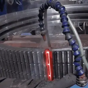
Induction hardening of cast iron uses an alternating magnetic field to generate heat inside a cast iron part, followed by rapid quenching to raise its hardness. HLQ applied this process to ductile (nodular) iron pulleys: each pulley was heated to 1600 °F (871.1 °C) in a four-turn helical coil and quenched in an agitated water bath to achieve 55 Rockwell C.
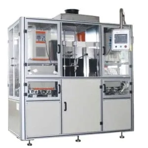
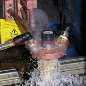
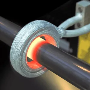
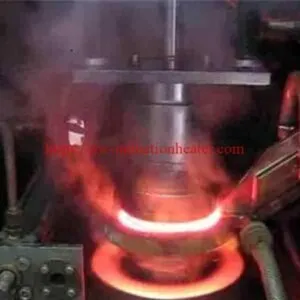
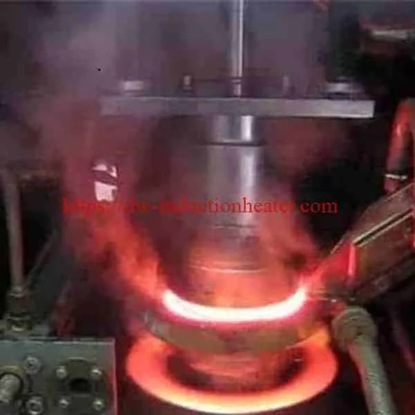
 The case drawing shows the cast iron pulley being placed into the four-turn helical coil, which is connected to the heat station.
Key Applications
| Cast iron part | Source |
|---|---|
| Ductile iron pulleys | This HLQ case |
| Gears, cams, guideways and wear surfaces (ductile cast iron) | HLQ induction hardening coil for steel surface hardening |
| Rollers, guide parts, wear surfaces (ductile iron) | HLQ 15 key FAQs about induction hardening machines |
| Guideways and sliding surfaces (gray cast iron) | HLQ induction hardening coil page |
| Camshaft and crankshaft profiles (ductile iron) | HLQ induction hardening coil page |
For steel parts, see induction hardening treatment, the induction shaft hardening machine and induction hardening knife blade.
Suitable Materials
| Material | Typical grades | HLQ guidance |
|---|---|---|
| Ductile iron (this case) | QT500, QT600, QT700, nodular cast iron | Good: used for gears, cams, guideways and wear surfaces; matrix structure affects hardening response (coil page). Possible: requires process testing to avoid cracking (FAQ). Requires careful control to avoid cracking, local melting or unstable hardness (gear hardening machine page). |
| Gray cast iron | HT250, HT300 | Conditional: can be surface hardened for guideways and sliding surfaces, but process control is critical |
| Medium carbon steel | 45 steel, C45, 1045, 50 steel | Very suitable |
| Alloy steel | 40Cr, 42CrMo, 4140, 4340 | Very suitable |

| Material | Typical surface hardness after induction hardening | Common application |
|---|---|---|
| 45 steel / C45 / 1045 | HRC 50–58 | Shafts, sprockets, pins |
| 40Cr / 5140 | HRC 52–60 | Gears, shafts, transmission parts |
| 42CrMo / 4140 | HRC 50–60 | Heavy-duty shafts, rollers, gears |
| Bearing steel | HRC 58–64 | Bearing races, precision parts |
| Ductile iron | HRC 45–55 (pulley case: 55 HRC) | Rollers, guide parts, wear surfaces |
Working Principle

The DW-UHF-10kW supplies 164 kHz current to the remote workhead (eight capacitors totaling 0.66 µF) and the four-turn helical coil. The alternating magnetic field induces eddy currents in the ductile iron pulley, which reaches 1600 °F (871.1 °C) after 2 minutes 45 seconds. Immediately afterwards the pulley is quenched in an agitated water bath, and the rapid cooling produces the 55 HRC hardness.
Current density follows the skin effect. Calculation (δ = 503·√(ρ/f), steel approximation for hot iron above the Curie point, ρ ≈ 1.2×10⁻⁶ Ω·m, µr = 1): at 164 kHz, δ ≈ 1.4 mm.
Technical Specifications
| Parameter | Case data |
|---|---|
| Objective | Heat cast iron pulleys to 1600 °F (871.1 °C) to achieve a hardness of 55 Rockwell C |
| Material | Ductile iron pulleys |
| Part size | 3 1/2″ (88.9 mm) OD, 2″ (50.8 mm) high |
| Temperature | 1600 °F (871.1 °C) |
| Frequency | 164 kHz |
| Equipment | DW-UHF-10kW induction heating system with a remote workhead containing eight (8) capacitors totaling 0.66 µF |
| Coil | Four-turn helical coil, designed and developed specifically for this application |
| Heating time | 2 minutes 45 seconds (165 s) |
| Quench | Immediately following heating, in an agitated water bath |
| Hardness | 55 Rockwell C |
| Benefits | Increased production; repeatable, non-contact and energy efficient heat; precise heating |
Recommended Model Selection
This case used the DW-UHF-10kW. The series data comes from the HLQ induction heating device model table.
| Model | Power | Max. input current | Frequency | Supply |
|---|---|---|---|---|
| DW-UHF-4.5kW | 4.5 kW | 20 A | 1.1–2.0 MHz | 1-phase 220 V |
| DW-UHF-6.0kW | 6.0 kW | 28 A | 300–1100 kHz | 1-phase 220 V |
| DW-UHF-10kW (this case) | 10 kW | 15 A | 100–500 kHz | 3-phase 380 V |
| DW-UHF-20kW | 20 kW | 30 A | 50–250 kHz | 3-phase 380 V |
| DW-UHF-30kW | 30 kW | 45 A | 50–200 kHz | 3-phase 380 V |
| DW-UHF-40kW | 40 kW | 60 A | 50–200 kHz | 3-phase 380 V |
| DW-UHF-60kW | 60 kW | 90 A | 50–150 kHz | 3-phase 380 V |
All DW-UHF models are rated for 100% duty cycle. The DW-UHF-10kW product page also lists frequency options of 50–300 kHz or 100–500 kHz.
| HLQ coil reference for cast iron parts | Materials | Power | Frequency |
|---|---|---|---|
| Guideway and rail hardening coil | Cast iron, alloy steel | 80–300 kW | 5–50 kHz |
| Camshaft and crankshaft profile hardening coil | Alloy steel, ductile iron | 100–350 kW | 3–30 kHz |
Process Workflow

- Load – a ductile iron pulley, 3 1/2″ (88.9 mm) OD × 2″ (50.8 mm) high.
- Position – place the pulley inside the four-turn helical coil.
- Heat – heat for 2 minutes 45 seconds at 164 kHz with the DW-UHF-10kW.
- Temperature – the pulley reaches 1600 °F (871.1 °C).
- Quench – quench immediately in an agitated water bath.
- Test – check for 55 Rockwell C.
HLQ’s general induction hardening flow also includes tempering after hardening to reduce brittleness. The pulley case does not mention tempering.

Common Problems and Solutions
| Problem | Cause / risk | Solution (HLQ guidance) |
|---|---|---|
| Cracking | Ductile iron hardening response; quench severity | Run process testing before production; control quench flow rate, pressure and medium concentration |
| Local melting | Overheating of cast iron | Careful control of power, frequency, coil gap and heating time |
| Unstable hardness | Matrix structure affects the hardening response | Process testing for each iron grade; the same heating time and immediate quench every cycle |
| Hardness below target | Delay before quench | Quench immediately after heating, as in this case (agitated water bath) |
| Brittleness after hardening | Untempered martensite | Tempering: control temperature and holding time |
Inspection per HLQ: hardness (HRC), effective case depth, microstructure and cracks.
Engineering Selection Guide
| Required case depth | Typical frequency range | Typical workpieces |
|---|---|---|
| 0.5–1.5 mm | High frequency (30–200 kHz) | Small pins, small shafts, light gears |
| 1.5–3 mm | Super-audio frequency (10–30 kHz) | Medium gears, sprockets, shafts |
| 3–6 mm | Medium frequency (1–10 kHz) | Large shafts, rollers, heavy gears |
| 6–10 mm | Low-medium frequency | Large rollers, mining parts, large shafts |
| Frequency | Calculated skin depth (hot ferrous, µr = 1, ρ ≈ 1.2×10⁻⁶ Ω·m) |
|---|---|
| 50 kHz | ≈ 2.5 mm |
| 164 kHz (this case) | ≈ 1.4 mm |
| 300 kHz | ≈ 1.0 mm |
| 500 kHz | ≈ 0.8 mm |
- Material grade determines hardenability and crack risk; state ductile or gray iron and the grade.
- Hardening area determines the coil design; encircling coils suit shafts, pins, rollers and rings.
- Required hardness and case depth determine the heating, quenching and frequency.
- Production capacity and available power supply determine automation and electrical design.
Advantages and Limitations
| Advantages | Limitations |
|---|---|
| Increased production | Ductile iron needs process testing to avoid cracking |
| Repeatable, non-contact and energy efficient heat | Gray cast iron is conditional; process control is critical |
| Precise heating | The coil must be designed for each part |
| Hardness up to 55 HRC on ductile iron (this case) | Immediate quenching must be built into the station |
Why Choose HLQ?
- A documented ductile iron case: 1600 °F (871.1 °C), 164 kHz, 55 HRC.
- Published material guidance for ductile and gray cast iron.
- A DW-UHF range from 4.5 kW to 60 kW, all rated for 100% duty cycle, plus hardening machines and coils for larger parts.
- Coils designed and developed specifically for each application.
10 Core FAQs
1. What was hardened in this case?
Ductile iron pulleys measuring 3 1/2″ (88.9 mm) OD and 2″ (50.8 mm) high.
2. What hardness was achieved?
55 Rockwell C.
3. What temperature was used?
1600 °F (871.1 °C).
4. How long is the heating cycle?
2 minutes and 45 seconds.
5. Which equipment and frequency were used?
A DW-UHF-10kW at 164 kHz with a remote workhead containing eight capacitors totaling 0.66 µF.
6. Which coil was used?
A four-turn helical coil designed and developed specifically for this application.
7. How is the pulley quenched?
Immediately after heating, in an agitated water bath.
8. Can gray cast iron be induction hardened?
HLQ lists gray cast iron (HT250, HT300) as conditional: it can be surface hardened for guideways and sliding surfaces, but process control is critical.
9. What hardness can ductile iron reach?
HLQ’s reference range for ductile iron is HRC 45–55; this pulley case reached 55 HRC.
10. What information is needed for a quotation?
The part drawing, iron grade, hardening area, hardness and case depth, output, and available power supply and cooling water.