

Induction Forging Steel Rod End
Induction Forging Steel Rod End: 1/8″–1/2″ Rods to 1800 °F in Under 5 Seconds
Quick Answer
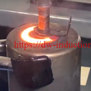
Induction forging of steel rod ends heats only the end of the rod to forging temperature before it is pressed into shape. In this HLQ case, the ends of steel rods from 1/8″ to 1/2″ diameter were heated to 1800 °F (982 °C) for forging a push rod end. The centre had to exceed 1400 °F (760 °C), while the outer edge could reach 1900 °F (1038 °C). A DW-HF-45kW solid state induction power supply at 50 kHz, with a remote heat station of 2 capacitors totaling 0.5 µF and a 6-turn (3 over 3) coil, heated both rod diameters to 1800 °F in less than 5 seconds, as measured by an optical pyrometer.
Table of Contents
- What is Induction Forging of Steel Rod Ends?
- Key Applications
- Suitable Materials
- Working Principle
- Technical Specifications
- Recommended Model Selection
- Process Workflow
- Common Problems and Solutions
- Engineering Selection Guide
- Advantages and Limitations
- Why Choose HLQ?
- 10 Core FAQs
What is Induction Forging of Steel Rod Ends?
Induction forging of steel rod ends is an end-heating process: only the part of the rod that will be formed is placed in the induction coil and heated to forging temperature. In the HLQ case, processing of the rods includes heating, pressing in a two-part die to forge the push rod end, and a final heating in a channel coil to temper the rods and relieve the forging stresses. The customer needed to process rods of different diameters between 1/8″ and 1/2″. For the wider process, see induction forging and hot forming.
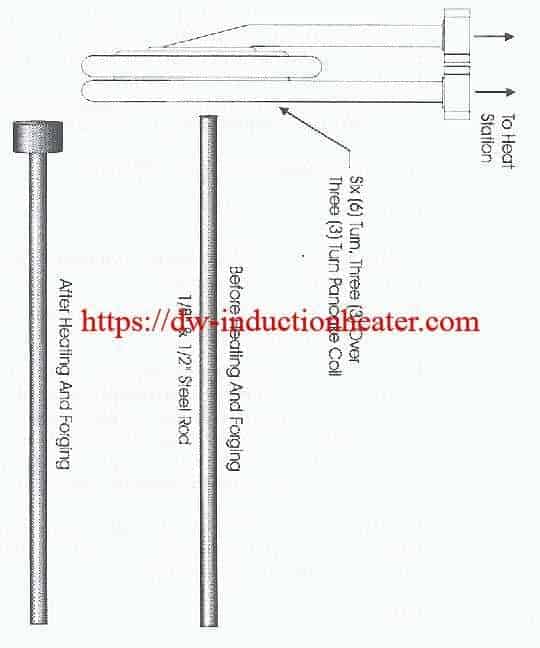
 The case drawing shows a 1/8″–1/2″ steel rod before and after heading and forging, and the six-turn, three-over-three coil connected to the heat station.
Key Applications
- Push rod ends: steel rod ends heated to 1800 °F and forged in a two-part die (this case).
- Bar, pipe and axle ends: partial forming and forging; see induction heating end of rods, billets and bars.
- Tempering after forging: final heating in a channel coil to relieve forging stresses.
| HLQ forging case | Part | Temperature | Time | Frequency / equipment |
|---|---|---|---|---|
| Steel rod ends (this page) | Rods 1/8″–1/2″ diameter | 1800 °F (982 °C) | < 5 s | 50 kHz, DW-HF-45kW |
| Induction forging steel strip | 1025 steel strip, 13″ section | 1800 °F | 10 s | 50 kHz |
| Titanium rod blanks | Ø15 × 300 mm | 2030 °F (1110 °C) | 25 s | 60 kHz, DW-HF-45kW |
| Titanium rod for hot forming | Ø31.8 × 127 mm | 1700 °F (926.7 °C) | 60 s | 70 kHz, DW-HF-60kW |

Suitable Materials
| Material | Data | Source |
|---|---|---|
| Steel rods, 1/8″ (3.2 mm) to 1/2″ (12.7 mm) | 1800 °F; centre above 1400 °F; outer edge up to 1900 °F | This case |
| Steel or stainless steel rods | Heated to 1200 °C in MF bar-end forging furnaces | HLQ bar-end forging furnace data |
| Copper or brass rods | Heated to 700 °C in MF bar-end forging furnaces | HLQ bar-end forging furnace data |
Carbon steel is magnetic below the Curie point and heats efficiently by induction; above it, the skin depth increases.
Working Principle

The DW-HF-45kW supplies 50 kHz current to the remote heat station (2 capacitors totaling 0.5 µF) and the 6-turn (3 over 3) coil. Only the rod end sits inside the coil. Eddy currents heat the outer layer, and heat conducts towards the centre, which must exceed 1400 °F without the surface exceeding 1900 °F.
Heating depth follows the skin effect. Calculation (δ = 503·√(ρ/f), hot steel above the Curie point, ρ ≈ 1.2×10⁻⁶ Ω·m, µr = 1):

| Rod | δ at 50 kHz | d/δ at 50 kHz | d/δ at 80 kHz | Limit reported in the case |
|---|---|---|---|---|
| 1/8″ (3.2 mm) | ≈ 2.5 mm | ≈ 1.3 | ≈ 1.6 | Induction heating efficiency |
| 1/2″ (12.7 mm) | ≈ 2.5 mm | ≈ 5.2 | ≈ 6.5 | Time to transfer heat to the centre (1400 °F) without melting the surface |
Case finding: larger diameter bars progressively heated faster, up to the thermal conductivity restrictions.
Technical Specifications
| Parameter | Case data |
|---|---|
| Objective | Heat the ends of steel rods to 1800 °F prior to a forging operation |
| Material | Steel rods of different diameters from 1/8″ (3.2 mm) to 1/2″ (12.7 mm) |
| Temperature | 1800 °F (982 °C) |
| Centre temperature | Above 1400 °F (760 °C) |
| Outer edge temperature | Up to 1900 °F (1038 °C) |
| Frequency | 50 kHz |
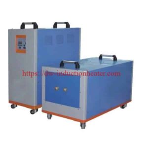
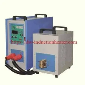
| Equipment | DW-HF-45kW output solid state induction power supply with a remote heat station containing 2 capacitors totaling 0.5 µF |
| Coil | 6-turn (3 over 3) coil |
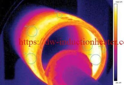
| Result | Both diameter steel rods reached 1800 °F in less than 5 seconds, measured by an optical pyrometer |
| Following operations | Pressing in a two-part die to forge the push rod end; final heating in a channel coil to temper and relieve forging stresses |
Recommended Model Selection
Specifications of the DW-HF-45kW induction heating equipment:
| Parameter | DW-HF-45kW |
|---|---|
| Input power supply | 3 × 380 V, 50–60 Hz |
| Oscillating power / max. input power | 45 kVA / 50 kVA |
| Oscillating frequency | 30–80 kHz |
| Oscillating current | 15–90 A |
| Duty cycle | 100% at 30 °C |
| Cooling water | ≤ 0.3 MPa, ≥ 6 L/min |
| Host / extension size | 550 × 240 × 535 mm / 470 × 265 × 440 mm |
| Weight / cable length | ≈ 75 kg / 2 m |
For larger rods, HLQ medium-frequency furnaces for induction forging end of bar and rod:
| Model | Max. input power | Rod range | Steel or stainless to 1200 °C | Copper or brass to 700 °C |
|---|---|---|---|---|
| MF-35 | 35 kW | Ø15–30 mm | 1.25 kg/min | 1.75 kg/min |
| MF-45 | 45 kW | – | 1.67 kg/min | 2.33 kg/min |
| MF-70 | 70 kW | Ø15–50 mm | 2.5 kg/min | 3.5 kg/min |
| MF-90 | 90 kW | Ø25–50 mm | 3.33 kg/min | 4.67 kg/min |
| MF-110 | 110 kW | – | 4.17 kg/min | 5.83 kg/min |
| MF-160 | 160 kW | Ø50 mm and up | 5.83 kg/min | 8.26 kg/min |
Model data: HLQ induction heating device table and bar-end furnace page.
Process Workflow

- Load – a steel rod of 1/8″–1/2″ diameter.
- Insert – place the rod end in the 6-turn (3 over 3) coil.
- Heat – heat to 1800 °F in less than 5 seconds at 50 kHz.
- Measure – check with an optical pyrometer; the centre must exceed 1400 °F.
- Forge – press in a two-part die to forge the push rod end.
- Temper – final heating in a channel coil to temper the rods and relieve forging stresses.

Common Problems and Solutions
| Problem | Possible cause | Solution |
|---|---|---|
| Centre below 1400 °F on 1/2″ rods | Time needed to transfer heat from the outside edge to the centre | Allow enough heating time while keeping the outer edge at or below 1900 °F (case) |
| Surface melting risk | Power density too high for the diameter | Limit surface temperature; the case allowed the outer edge up to 1900 °F |
| Slow heating of 1/8″ rods | Low induction heating efficiency on a small diameter (case) | Match frequency and coil to the diameter |
| Heating speed too slow | Coil gap too large or wrong coil design | Optimize the coil shape or reduce the coil gap |
| Uneven heating | Workpiece not centred or coil field uneven | Improve the fixture; rotate the workpiece if needed |
| Surface oxidizes | Overheating or long exposure in air | Reduce heating time |
| Coil overheats | Insufficient cooling water or a blocked channel | Check water flow (≥ 6 L/min), pressure (≤ 0.3 MPa) and water quality |
Data from this case and the HLQ DW-HF-45kW product page.
Engineering Selection Guide
| Rod size / task | HLQ reference |
|---|---|
| Ø1/8″–1/2″ (3.2–12.7 mm) rod ends | DW-HF-45kW, 50 kHz (this case) |
| Ø15–30 mm rods | MF-35 bar-end forging furnace |
| Ø15–50 mm rods | MF-70 |
| Ø25–50 mm rods | MF-90 |
| Ø50 mm and larger | MF-160 |
| Large billet forging (100–1000 kW+, 1–10 kHz) | Not recommended for DW-HF-45kW; choose a medium frequency system, such as the induction forging bar and billet furnace |
- Temperature window: define both the centre minimum and the surface maximum, as in this case (centre > 1400 °F, edge ≤ 1900 °F).
- Diameter range: small diameters are limited by efficiency and large diameters by heat conduction, so test the smallest and largest rods.
- Data to send: steel grade, rod diameters, heated length, temperature limits, parts per hour, supply voltage and cooling water.
Advantages and Limitations
| Advantages | Limitations |
|---|---|
| 1800 °F in less than 5 seconds for both rod diameters | Small rods are limited by induction heating efficiency |
| Only the rod end is heated | Large rods are limited by heat conduction to the centre |
| One station covers 1/8″ to 1/2″ rods | The coil must be designed for the rod range |
| Temperature verified by optical pyrometer | Water cooling is required |
Why Choose HLQ?
- A documented rod end case: 1800 °F in under 5 seconds on 1/8″–1/2″ rods.
- DW-HF power supplies for small rods and MF bar-end forging furnaces from 35 to 160 kW for larger rods.
- Coils designed for end heating, such as the 3-over-3 coil in this case.
- Forging cases in steel rods, steel strip and titanium rods.
10 Core FAQs
1. What was heated in this case?
The ends of steel rods from 1/8″ to 1/2″ diameter, before forging a push rod end.
2. What temperature was required?
1800 °F (982 °C), with the centre above 1400 °F and the outer edge up to 1900 °F.
3. How fast were the rods heated?
Both rod diameters reached 1800 °F in less than 5 seconds.
4. How was the temperature measured?
With an optical pyrometer.
5. Which equipment was used?
A DW-HF-45kW solid state induction power supply with a remote heat station of 2 capacitors totaling 0.5 µF.
6. What frequency was used?
50 kHz.
7. Which coil was used?
A 6-turn (3 over 3) coil.
8. Why are small and large rods limited differently?
The 1/8″ rod was limited by induction heating efficiency; the 1/2″ rod by the time needed to bring the centre to 1400 °F without melting the surface.
9. What happens after the end is forged?
A final heating in a channel coil tempers the rods and relieves the forging stresses.
10. What information is needed for a quotation?
The steel grade, rod diameters, heated length, centre and surface temperature limits, output, and available power supply and cooling water.