
Induction Annealing Saw Blades
Induction Annealing Saw Blades: Process, Equipment, Technical Specifications and Engineering Guide
Quick Answer
Induction annealing of saw blades is a heat-treatment application in which an alternating electromagnetic field heats a selected area of a steel saw blade or blade strip. The process can be used to modify local material properties before further manufacturing operations, such as hole punching, provided that the required thermal cycle and metallurgical results are verified.
One published application involves continuous 400-series stainless steel strips used to manufacture bread-cutting saw blades. The strips are 0.38 inch (9.6 mm) and 0.51 inch (12.9 mm) wide, with a localized 1.2-inch (30.5 mm) section heated before punching holes.
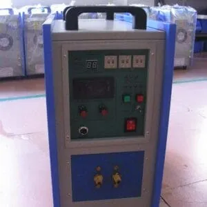
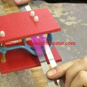
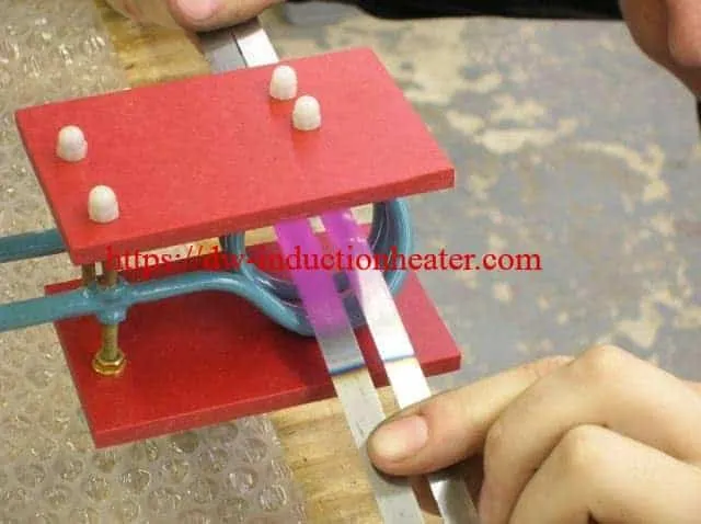
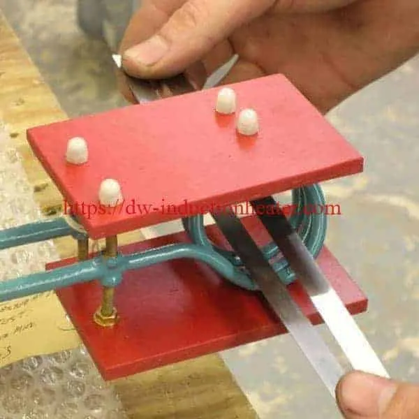
The original HLQ product page identifies a DW-UHF-6kW-III induction heating system, a nominal operating frequency of 400 kHz, a remote workhead containing one 1.00 microfarad capacitor, and a three-turn helical induction coil positioned at approximately 45 degrees.
Technical verification note: These are the values published on the original page, not an independently verified HLQ production test. The original temperature notation, “600°C (315.6°F),” is inconsistent. A valid process setpoint cannot be established from these figures without further verification.
Unlike induction hardening, which is intended to increase hardness in suitable steels, induction annealing is generally intended to produce a specified softer or stress-relieved material condition. The exact thermal cycle depends on the steel grade, initial condition, geometry and required final properties.
Table of Contents
- What Is Induction Annealing for Saw Blades?
- Key Applications
- Suitable Materials
- Working Principle
- Technical Specifications
- Recommended Model Selection
- Process Workflow
- Common Problems and Solutions
- Engineering Selection Guide
- Advantages and Limitations
- Why Choose HLQ?
- 6 Core FAQs
What Is Induction Annealing for Saw Blades?
Induction annealing is a controlled thermal process that uses electromagnetic induction to generate heat within an electrically conductive workpiece.
When applied to a saw blade, an induction coil produces a changing magnetic field that induces electrical currents within the steel. Electrical resistance converts part of this energy into heat.
The resulting temperature distribution depends on the steel composition, initial microstructure, operating frequency, power delivery, induction coil geometry, heating duration and thermal boundary conditions.
For bread-cutting saw blade strips, localized induction heating can be applied to a selected region before a hole-punching operation. The objective is to obtain the material condition required for punching without unnecessarily heating the entire strip.
However, successful electromagnetic heating does not automatically establish successful metallurgical annealing. The required properties must be confirmed through appropriate process testing.
For a broader explanation of metal softening and stress-relief processes, see the induction annealing process.
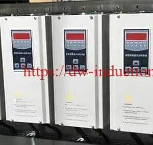
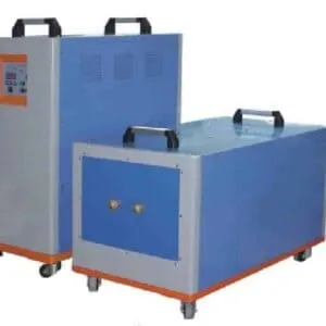
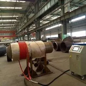
Original Saw Blade Annealing Equipment Images
Difference Between Annealing, Tempering and Hardening
| Process | Primary Objective | Engineering Considerations |
|---|---|---|
| Annealing | Obtain a specified softer, more workable or stress-relieved condition | Requires grade-specific temperature, holding and cooling conditions |
| Stress-Relief Treatment | Reduce residual stresses caused by previous manufacturing operations | The temperature must be compatible with the existing material condition |
| Tempering | Modify properties after hardening in suitable steels | Depends on the initial hardened microstructure and specified final hardness |
| Induction Hardening | Increase surface or edge hardness in hardenable steels | Requires appropriate austenitizing and quenching conditions |
These operations are not interchangeable. For example, hardening saw teeth requires a different thermal process from locally softening a strip before punching.
For a separate application involving increased tooth hardness, see induction hardening of saw blades.
Key Applications
1. Localized Annealing Before Hole Punching
The original published application involves 400-series stainless steel bread-cutting saw blade strips. A selected region is heated before holes are punched into the strip.
Localized treatment may be evaluated to reduce the risk of punching-related cracking and other defects when the untreated material condition is unsuitable for the forming operation.
The improvement must be confirmed by comparing treated and untreated samples under the same punching conditions.
2. Controlled Hardness Adjustment of Band Saw Blades
A separate published induction heating application demonstrates controlled hardness reduction, sometimes described as drawing back, in steel band saw blades.
In that application, the objective was to obtain a Rockwell C hardness between 50 and 52 with controlled variation between the saw teeth and the back of the blade.
This is a different operation from the bread-cutting saw blade hole-punching application, and its parameters should not be transferred directly to other blade materials.
3. Localized Stress-Relief Treatment
Induction heating can be evaluated for local stress-relief applications where the material specification permits selective thermal treatment.
The final process must account for existing hardness, residual stress distribution, component geometry and possible changes in material properties.
4. Continuous Steel Strip Processing
A suitable induction heating station can be incorporated into a continuous strip-processing system.
For automated production, the line design must account for strip feeding, positioning, coil clearance, operating speed, heating-zone length, temperature monitoring and downstream operations.
5. Thermal Processing of Cutting Tools
Other steel cutting tools may be candidates for induction heating or heat treatment, but each application requires independent verification.
In particular, high-speed steel blades, bimetal band saw blades, carbide-tipped circular saws and conventional stainless steel strips cannot be assumed to require the same thermal treatment.
Suitable Materials
The existing HLQ application specifically identifies continuous strips made from 400-series stainless steel but does not identify the exact steel grade.
The 400-series classification includes stainless steels with different microstructures and heat-treatment responses. Consequently, the material certificate is necessary before a suitable annealing schedule can be specified.
Stainless Steel Grades and Treatment Considerations
| Steel Grade | UNS Designation | Steel Family | Heat-Treatment Consideration |
|---|---|---|---|
| AISI 410 | S41000 | Martensitic stainless steel | Can be hardened and tempered; the required treatment depends on the initial condition |
| AISI 420 | S42000 | Martensitic stainless steel | Used in cutting-tool applications; annealing and tempering require grade-specific schedules |
| AISI 430 | S43000 | Ferritic stainless steel | Not hardenable by conventional quench-hardening heat treatment; annealing conditions differ from martensitic grades |
| Unspecified 400-Series Stainless Steel | Not provided | Cannot be confirmed | Exact grade and treatment requirements must be established before specifying temperature and time |
The material designations above are examples of stainless steel grades, not confirmation that the original bread saw blade was manufactured from any specific one of them.
Published Grade 430 Heat-Treatment Reference
The following values are published reference temperatures for AISI 430 stainless steel. They are provided to illustrate the importance of alloy-specific heat-treatment schedules. They are not validated settings for the original saw blade application.
| Grade | Treatment | Published Temperature | Cooling Requirements |
|---|---|---|---|
| AISI 430 | Solution annealing | 815–845°C | Slow furnace cooling to 600°C, followed by rapid air cooling according to the referenced procedure |
| AISI 430 | Subcritical annealing | 760–815°C | Air cooling or water quenching as described in the referenced material guide |
Working Principle
The induction annealing process transfers electromagnetic energy from a high-frequency power supply to the steel saw blade strip through a specially designed induction coil.
Electromagnetic Heating Sequence
- The induction power supply produces alternating current at the operating frequency of the matched system.
- The current passes through the induction workhead and copper heating coil.
- The alternating current generates a time-varying magnetic field around the coil.
- The changing magnetic field induces electrical currents within the electrically conductive blade material.
- Electrical resistance converts the induced current energy into heat.
- The resulting thermal distribution is controlled by the electrical and thermal properties of the material, the coil geometry and the applied heating cycle.
Steel magnetic properties can also influence the electromagnetic heating process, particularly as temperature changes. The relevant material properties must be considered when selecting power and frequency.
Learn more about the underlying electromagnetic process in the induction heating fundamentals.
Original Coil Arrangement
The original application describes a three-turn helical induction coil positioned at approximately 45 degrees to the saw blade strip.
This arrangement is intended to produce localized heating in the section of strip that requires treatment before hole punching.
Actual coil performance depends on the workpiece size, coil dimensions, position, coupling, output matching and operating conditions. Reproducing the turn count and angle alone does not guarantee the same heating result.
Induction Coil Design Factors
| Design Factor | Effect on Heating | Engineering Requirement |
|---|---|---|
| Coil shape | Determines electromagnetic coupling and heating distribution | Match the coil to the blade and selected heating zone |
| Number of turns | Influences inductance and electromagnetic coupling | Coordinate coil selection with the matching network |
| Coil-to-workpiece clearance | Affects coupling, power transfer and repeatability | Maintain suitable clearance with stable workpiece positioning |
| Operating frequency | Influences current distribution and penetration | Select according to material properties and heating requirements |
| Applied power | Influences heating rate | Validate delivered power and temperature response |
| Heating duration | Affects temperature rise and heat spreading | Verify the complete time-temperature cycle |
| Cooling-water circuit | Removes heat from the coil and associated equipment | Confirm the manufacturer’s required flow, pressure and temperature |
Additional examples of induction coil designs are available for different heating geometries.
Technical Specifications
Original HLQ Page — Published Application Parameters
The following information is retained from the existing product page. These specifications must be distinguished from a verified equipment performance test.
| Parameter | Published Value | Engineering Verification |
|---|---|---|
| Application | Induction annealing of saw blades | Original application description |
| End product | Bread-cutting saw blades | Original application description |
| Material | 400-series stainless steel | Exact grade not specified |
| Strip width | 0.38 inch / 9.6 mm | Original published dimension |
| Alternative strip width | 0.51 inch / 12.9 mm | Original published dimension |
| Heating region | 1.2 inch / 30.5 mm | Original published dimension |
| Induction power supply | DW-UHF-6kW-III | Original page model identification |
| Nominal equipment rating | 6 kW | Not verified as actual power delivered to the blade |
| Published working frequency | 400 kHz | Requires verification against the specific model configuration |
| Remote workhead | One 1.00 microfarad capacitor | Original published configuration; electrical matching must be confirmed |
| Induction coil | Three-turn helical coil | Original published configuration |
| Coil orientation | 45 degrees | Original application description |
| Published heating duration | 1 second | Not independently verified as a complete annealing cycle |
| Original temperature notation | 600°C (315.6°F) | Incorrect conversion; actual process temperature unresolved |
| Production capacity | Not specified | No verified parts-per-minute or strip-speed value available |
Critical Temperature Clarification
The original page prints “600°C (315.6°F).” This is not a valid temperature conversion.
| Temperature | Correct Equivalent |
|---|---|
| 600°C | 1112°F |
| 600°F | 315.6°C |
The intended setpoint cannot be established from the conflicting original notation. A verified process record is necessary before either value can be used in an equipment specification or production recipe.
Independent Published Reference — Stainless Steel Bread Saw Blades
Ambrell publishes an application involving annealing of stainless steel bread-cutting saw blades before hole punching. The publicly available information reports the following:
| Parameter | Published Ambrell Reference |
|---|---|
| Application | Annealing bread-cutting saw blade strips before hole punching |
| Material | 400-series stainless steel |
| Strip widths | 9.6 mm and 12.9 mm |
| Equipment | Ambrell 4.2 kW induction heating system |
| Operating frequency | 289 kHz |
| Workhead capacitor | 1.00 microfarad |
| Coil | Three-turn helical coil at approximately 45 degrees |
| Heating zone | 30.5 mm |
Separate Published Reference — Saw Blade Hardness Adjustment
A different Ambrell application demonstrates induction heating for drawing back the hardness of steel band saw blades.
| Parameter | Published Reference Value |
|---|---|
| Equipment | 7.5 kW induction heating power supply |
| Operating frequency | 80 kHz |
| Published temperature | 700°F / approximately 371°C |
| Blade width | 2.125 inches |
| Blade thickness | 0.042 inch |
| Processing speed | 60 inches per minute |
| Target hardness | 50–52 HRC |
| Reported mean hardness | 50.3 HRC, measured on fifteen saw teeth |
Recommended Model Selection
Induction annealing equipment must be selected by matching the material, strip geometry, treatment temperature, heating duration, required penetration, coil design and production requirements.
The generator’s rated power alone cannot determine whether the annealing process will be successful.
HLQ Published Equipment Comparison
| Model / Series | Published Rating | Frequency Information | Selection Assessment |
|---|---|---|---|
| DW-UHF-6kW-III | 6 kW | 400 kHz stated on the original application page | Original application model; confirm the actual equipment version and operating-frequency specification |
| DW-UHF-6.0 | 6.0 kW | 1.1–2.0 MHz in current published equipment summary | Not directly interchangeable with the reported 400 kHz configuration without further verification |
| DW-UHF-10 | 10 kW | 100–500 kHz | Candidate for evaluation where an operating frequency around 400 kHz is required |
| DW-UHF-20 | 20 kW | 50–250 kHz | Frequency range does not include 400 kHz; may be evaluated only if a different frequency is technically suitable |
The equipment frequency ranges above are taken from published HLQ product information. They are not guarantees of heating speed, temperature accuracy or finished blade properties.
A higher nominal power rating does not automatically provide a better heating pattern or more suitable metallurgical result.
For the original small-strip application, a valid selection process should confirm the exact 6 kW equipment configuration and compare it with any alternative model against the required coil and thermal profile.
Explore available induction heating power supplies for published frequency and power ranges.
Information Required for Final Equipment Selection
| Required Input | Purpose |
|---|---|
| Exact steel grade | Determine material properties and treatment requirements |
| Initial material condition | Establish starting hardness and microstructure |
| Strip width and thickness | Determine thermal load and electromagnetic coupling |
| Required heating-zone length | Define the coil and treatment region |
| Target temperature and holding requirements | Establish a valid process recipe |
| Strip speed or cycle time | Determine required power delivery and line integration |
| Target hardness or punchability | Define the acceptance criteria |
| Electrical supply | Verify generator compatibility |
| Cooling system | Confirm generator and coil cooling requirements |
| Handling and control system | Determine positioning, monitoring and automation requirements |
Process Workflow
A controlled saw blade induction annealing process requires a defined manufacturing sequence, with traceable settings and inspection criteria.
Step 1 — Identify the Blade Material
Confirm the steel grade, strip dimensions, initial hardness, material condition and the required final properties around the punching region.
Step 2 — Prepare the Fixture and Strip Feed
Position the blade strip relative to the induction coil. Verify clearance, alignment, strip orientation and the repeatability of the feeding mechanism.
Step 3 — Perform Induction Heating
Apply the selected power, frequency and heating duration using a coil matched to the material and required heating zone.
For a continuous production line, verify how strip speed and coil length affect the effective heating time.
Step 4 — Verify the Thermal Cycle
Measure the actual temperature distribution using a suitable validated measurement method.
Confirm that the selected region receives the specified thermal treatment without unacceptable heating of neighboring material.
Step 5 — Apply the Required Cooling Conditions
Allow or control cooling according to the specified steel grade and treatment requirements. The cooling method must not be assumed from the original one-second heating description.
Step 6 — Perform Hole Punching and Inspection
Carry out hole punching under controlled conditions. Inspect the resulting holes for cracking, edge defects, burr formation and dimensional conformity.
Where required, compare treated and untreated specimens using the same inspection criteria to establish whether localized induction heating provides a measurable improvement.
Suggested Process Validation Records
| Process Stage | Record or Measurement | Purpose |
|---|---|---|
| Incoming material | Steel grade, material certificate and initial hardness | Confirm starting material condition |
| Positioning | Fixture alignment and coil clearance | Improve process repeatability |
| Heating | Power setting, operating frequency and heating duration | Document applied process conditions |
| Temperature verification | Temperature profile and treated-zone location | Confirm the intended thermal treatment |
| Cooling | Cooling method and relevant process conditions | Maintain the specified material condition |
| Final inspection | Hole dimensions, defects and specified material properties | Establish treatment acceptance |
Common Problems and Solutions
| Problem | Possible Cause | Recommended Engineering Action |
|---|---|---|
| Cracking during hole punching | Inappropriate local material condition, insufficient treatment or unsuitable punching parameters | Review material certificate, process recipe, tooling and treated-sample results |
| Uneven heating across the strip | Incorrect coil position, coupling or strip alignment | Optimize coil geometry and verify the temperature distribution |
| Excessive softening | Uncontrolled heating or inappropriate thermal cycle | Verify temperature, duration, cooling and final hardness |
| Insufficient softening | Inadequate thermal exposure or incorrect metallurgical process | Confirm the actual temperature-time cycle against material requirements |
| Blade distortion | Nonuniform thermal gradients, handling or residual stress changes | Evaluate heat distribution, restraint, cooling and dimensional changes |
| Excessive oxidation | High-temperature exposure in an unsuitable atmosphere | Review the temperature-time cycle and determine whether atmosphere control is necessary |
| Unstable heating performance | Variations in coil clearance, electrical matching or workpiece position | Inspect fixture repeatability, coil integrity and matching conditions |
| Coil overheating | Inadequate cooling flow or unsuitable coil operating conditions | Inspect the cooling circuit and verify manufacturer operating limits |
| Inconsistent punching quality | Material variation, unstable thermal treatment or punching-tool condition | Apply controlled sampling, hardness inspection and process monitoring |
Engineering Selection Guide
1. Establish the Required Metallurgical Result
Define whether the required operation is localized annealing, softening, stress relief or tempering.
The purpose of the treatment should be expressed through measurable acceptance criteria, such as hardness, cracking resistance during punching or dimensional stability.
2. Confirm the Exact Saw Blade Steel
The expression “400-series stainless steel” is not sufficient for selecting a heat-treatment cycle.
Different grades have different compositions and microstructures. Their responses to temperature, holding time and cooling can be significantly different.
3. Determine the Heating-Zone Geometry
Identify the intended heating length and the required position of the treated area relative to the punching location.
Use the blade width, thickness, surface condition and orientation when evaluating the coil.
4. Calculate the Thermal Requirement
The sensible thermal energy required to raise the temperature of the treated mass can be expressed as:
Q = m × integral(cp(T) dT), from initial temperature to final temperature.
Where:
- Q is the thermal energy required by the material.
- m is the heated material mass.
- cp(T) is the temperature-dependent specific heat capacity.
This relationship describes the sensible heating requirement. Actual generator input must also account for electrical conversion losses, electromagnetic coupling, heat conduction, radiation, convection and operating conditions.
No reliable power requirement can be calculated for the original application without the missing strip thickness, confirmed material, valid target temperature and complete thermal cycle.
5. Select a Compatible Frequency
Induction frequency influences current distribution and the electromagnetic penetration depth.
It is therefore necessary to match frequency with workpiece geometry, magnetic properties, desired heating distribution and coil design.
A frequency published for another material or coil configuration should not be adopted without verification.
6. Design and Validate the Coil
Use a coil that produces the necessary heating pattern while maintaining mechanical clearance and suitable cooling.
The published three-turn, 45-degree arrangement is a reference configuration. It is not a universally suitable design for all blade dimensions.
7. Validate the Temperature Measurement Method
For small, moving steel strips, temperature measurement may be affected by emissivity, surface condition, measurement position and instrument response.
Use a measurement method with appropriate calibration and performance for the intended process.
8. Confirm the Complete Production Cycle
For continuous processing, the time available for heating depends on the relationship between strip speed and the effective length of the heating zone.
A first-order residence-time relationship is:
Heating residence time = Effective heating-zone length / Strip travel speed.
This relationship is useful for preliminary layout analysis, but it does not establish the actual temperature-time history or prove successful annealing.
9. Evaluate Cooling and Equipment Protection
Verify the power supply, workhead and coil cooling requirements against manufacturer documentation.
Cooling-water flow, pressure, inlet temperature, water quality and interlocks must be specified for the actual equipment configuration.
10. Qualify the Final Process
Complete representative production trials using the correct steel grade and actual punching equipment.
Confirm that the treated samples satisfy the specified material properties and product acceptance criteria before committing to production operation.
Conceptual Production-Line Layout
A possible automated layout includes strip feeding, positioning, an induction heating station, temperature monitoring, controlled cooling, hole punching and final inspection.
The RF generator and cooling system can be integrated with the heating station according to the final equipment configuration.
Actual machine dimensions, conveyor arrangement, safety guarding, electrical interfaces and production speed must be established during engineering design.
For additional equipment series and power ratings, see the HLQ guide to induction heating equipment selection.
Advantages and Limitations
Advantages of Induction Annealing
- Localized heating: Electromagnetic energy can be concentrated around a selected region of the blade strip.
- Non-contact heating: The induction coil does not need direct mechanical contact with the metal workpiece.
- Controllable energy delivery: Heating can be adjusted through the selected power supply and operating conditions.
- Potential production-line integration: A suitable station can be combined with strip feeding and manufacturing equipment.
- Process repeatability: Correct fixture design and monitored electrical settings can support consistent processing.
- Reduced unnecessary bulk heating: Localized treatment may avoid heating the complete strip when only a selected region requires treatment.
Limitations of Induction Annealing
- The process requires a coil designed for the workpiece geometry.
- The required thermal treatment depends on the exact steel grade and starting condition.
- Temperature uniformity and thermal penetration cannot be inferred from nominal frequency alone.
- Localized heating can produce thermal gradients and possible distortion.
- A short heating pulse does not automatically establish a complete metallurgical annealing cycle.
- Temperature measurement can be challenging on narrow or moving strips.
- The final hardness and punching performance must be verified by testing.
- Published data from a different manufacturer’s application cannot establish HLQ equipment performance.
Why Choose HLQ?
HLQ Induction Equipment Co., Ltd. publishes medium-frequency, high-frequency and ultra-high-frequency induction heating equipment for industrial metal-processing applications.
The published product range includes equipment used in induction annealing, brazing, hardening, metal heating and related applications.
For a saw blade annealing project, equipment evaluation should include a suitable power supply, matched induction coil, workpiece positioning, cooling provisions and the control functions needed for the specified process.
Published Equipment Capabilities and Project Requirements
| Equipment / Engineering Area | Relevant Information |
|---|---|
| High-frequency power supplies | HLQ publishes HF and UHF induction heating equipment with different power and frequency ranges |
| Original application model | DW-UHF-6kW-III is identified on the existing saw blade annealing page |
| Alternative model evaluation | DW-UHF-10 has a published frequency range of 100–500 kHz |
| Coil matching | Coil geometry and resonant matching must be verified for the actual workpiece |
| Cooling provisions | The selected generator and workhead require suitable cooling arrangements |
| Production integration | Feeding, positioning, monitoring and handling requirements must be established for the individual application |
| Process acceptance | Final heating performance and blade properties must be demonstrated through application testing |
These statements describe published equipment information and relevant engineering requirements. They do not claim an independently verified HLQ customer installation, production result or specific reduction in blade scrap rate.
6 Core FAQs
1. What is induction annealing of saw blades?
Induction annealing of saw blades uses an alternating electromagnetic field to heat a selected region of a steel blade or strip. The required thermal process is intended to produce a specified material condition, such as localized softening or stress relief. The final result must be verified against the material and product requirements.
2. Which materials can be used for saw blade induction annealing?
The original published bread-cutting saw blade application uses 400-series stainless steel strips. Other conductive steel materials can be heated by induction, but their suitability for annealing depends on the exact grade, starting condition and required properties. AISI 410, 420 and 430 have different heat-treatment responses and should not share one universal annealing recipe.
3. What is the correct annealing temperature for stainless steel saw blades?
There is no universal temperature for all stainless steel saw blades. The treatment temperature depends on the grade and intended metallurgical result. The original HLQ page contains an incorrect conversion, “600°C (315.6°F).” Therefore, the original process temperature remains unverified and must not be used as a confirmed operating setpoint.
4. What induction heating machine is suitable for this application?
The original HLQ page identifies a DW-UHF-6kW-III system operating at 400 kHz, but the exact equipment configuration requires verification. HLQ also publishes a DW-UHF-10 model rated at 10 kW with a frequency range of 100–500 kHz, making it a candidate for evaluation where approximately 400 kHz operation is required. Final equipment selection depends on coil design, the steel grade, thermal cycle and application testing.
5. What is the difference between induction annealing and induction hardening of saw blades?
Annealing is generally used to obtain a softer, more workable or stress-relieved material condition. Induction hardening is used to increase hardness in suitable steels through controlled heating followed by an appropriate quenching process. Tempering is another distinct treatment used to modify properties after hardening. The correct process must be selected according to the intended blade properties.
6. Can saw blade induction annealing be integrated into an automated production line?
Yes. Induction heating equipment can be incorporated into continuous strip-processing systems with feeding, positioning, heating, temperature monitoring and downstream punching equipment. However, the achievable production speed depends on the required thermal cycle, strip dimensions, coil design, equipment capacity and handling arrangement. Production performance must be established through representative process testing.