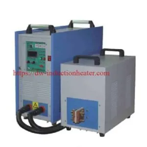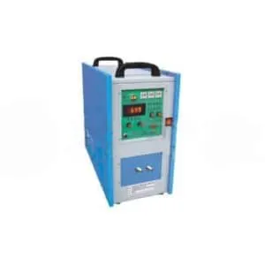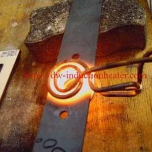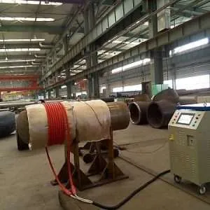


Induction Annealing Stainless Steel Rod
Induction Annealing Stainless Steel Rods: AISI 410/416 Stress Relief, Process and Equipment Guide
Quick Answer
Induction annealing stainless steel rods is a heat-treatment application in which an alternating electromagnetic field generates heat directly within electrically conductive stainless steel bars or shafts. Depending on the alloy grade and thermal cycle, induction heating can be used for localized stress relief, subcritical annealing or other specified heat-treatment operations.
The original HLQ application describes heating AISI 410 and AISI 416 stainless steel rods to 1200°F (approximately 649°C) using a DW-HF-60kW induction heating system operating at a published frequency of 70 kHz.
The application includes a 26.97 mm diameter AISI 410 rod and a 31.75 mm diameter AISI 416 rod, each approximately 1.83 m long. A two-position, eight-turn helical parallel induction coil is described, together with a remote workhead containing eight 1.0 µF capacitors, providing a total nominal capacitance of 8.0 µF.
The original page reports a heating time of 30 seconds to reach the target temperature. However, the exact heated length, measured temperature distribution, holding time, cooling method and final material properties are not provided.
Engineering clarification: Heating to approximately 649°C for 30 seconds does not, by itself, demonstrate complete annealing of the entire rod. This temperature is near the lower limit of published subcritical or process-annealing ranges for AISI 410 and AISI 416 stainless steel. Full annealing normally requires higher temperatures and controlled cooling.
Table of Contents
- What Is Induction Annealing Stainless Steel Rods?
- Key Applications
- Suitable Materials
- Working Principle
- Technical Specifications
- Recommended Model Selection
- Process Workflow
- Common Problems and Solutions
- Engineering Selection Guide
- Advantages and Limitations
- Why Choose HLQ?
- 6 Core FAQs
What Is Induction Annealing Stainless Steel Rods?
Induction annealing is a controlled heating process that uses electromagnetic induction to generate heat inside an electrically conductive workpiece.
When an alternating current passes through an induction coil, the resulting magnetic field induces electrical currents within the metal rod. Electrical resistance converts part of the induced-current energy into heat.
This allows an induction heating system to concentrate energy within a selected workpiece region, depending on coil design, frequency, power delivery, material properties and heating duration.
In stainless steel rod manufacturing, induction heating can be evaluated for stress relief, localized softening and other operations requiring controlled thermal input.
However, the term “annealing” refers to a metallurgical process, not merely the act of heating a metal to a specified temperature.
The actual heat-treatment result depends on the grade, initial microstructure, temperature, holding time, cooling conditions and final acceptance requirements.
For a more detailed explanation, see the induction annealing process.
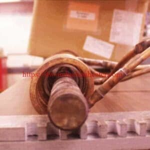
Original Stainless Steel Rod Induction Heating Images


Induction Stress Relief Versus Full Annealing
| Characteristic | Stress Relief / Subcritical Treatment | Full Annealing |
|---|---|---|
| Primary objective | Reduce residual stresses or modify the existing material condition | Obtain the specified annealed metallurgical condition |
| Temperature selection | Based on the material grade and required final properties | Based on the full-annealing requirements of the grade |
| Heating region | May be localized where the application permits | Must encompass the region required by the treatment specification |
| Holding period | Defined by the qualified treatment procedure | Defined by alloy, section size and material condition |
| Cooling | Selected according to the material and process | May require controlled slow cooling |
| Verification | Temperature history, dimensional stability and specified properties | Final hardness, microstructure and other specified material properties |
Key Applications
1. Localized Stress Relief of AISI 410 Stainless Steel Rods
AISI 410 is a martensitic stainless steel that can be hardened and tempered by appropriate heat treatment.
Induction heating can be considered for localized stress-relief or process-annealing operations when the steel’s starting condition and required final properties are known.
The original application identifies a 26.97 mm diameter AISI 410 rod with an overall length of approximately 1.83 m.
The published target temperature is approximately 649°C. This is close to the lower boundary of the commonly published 650–760°C process-annealing range.
The actual treatment must be qualified using the specified temperature-time and cooling conditions.
2. Heating AISI 416 Stainless Steel Bars
AISI 416 is a free-machining martensitic stainless steel. It contains sulfur additions to improve machinability compared with conventional AISI 410.
Induction heating may be evaluated for subcritical treatment or stress-relief operations where the required metallurgical properties permit.
The original application identifies a 31.75 mm diameter AISI 416 bar approximately 1.83 m long.
The appropriate heating and cooling conditions depend on whether the objective is stress relief, subcritical annealing or full annealing.
3. Localized Thermal Processing of Stainless Steel Shafts
Stainless steel shafts and other cylindrical components may require controlled heating after machining, forming or other manufacturing operations.
Induction heating allows a coil to be designed around a selected region of the shaft.
However, the suitability of localized treatment depends on the required temperature distribution, material condition and dimensional tolerances.
4. Integration into Industrial Bar Processing
Induction heating stations can be evaluated for integration with rod positioning, transfer mechanisms, temperature monitoring and automated process controls.
The potential production advantages depend on the required heating cycle, coil arrangement, handling system and material acceptance requirements.
The original page suggests that induction heating can be integrated into an in-line process. It does not supply independently verified production speed, energy-consumption or cost-savings measurements.
5. Heating Before Subsequent Manufacturing Operations
Where the manufacturing specification allows it, controlled induction heating can be considered before selected mechanical operations that require a particular material condition.
Any claimed improvement in machinability, ductility or residual-stress condition should be established through appropriate testing.
Suitable Materials
The original published application covers two specific martensitic stainless steel grades: AISI 410 and AISI 416.
These grades are different from austenitic stainless steels such as AISI 304 and AISI 316. Their heat-treatment temperatures and cooling requirements must not be assumed to be interchangeable.
AISI 410 and AISI 416 Material Comparison
| Material | AISI 410 | AISI 416 |
|---|---|---|
| UNS designation | S41000 | S41600 |
| Steel family | Martensitic stainless steel | Free-machining martensitic stainless steel |
| Primary distinguishing feature | General-purpose hardenable chromium stainless steel | Sulfur-modified grade for improved machinability |
| Heat-treatment capability | Can be hardened and tempered | Can be hardened and tempered |
| Full-annealing reference range | 815–900°C | 815–900°C |
| Process / subcritical annealing range | 650–760°C | 650–760°C |
| Cooling after subcritical treatment | Air cooling in published material reference | Air cooling in published material reference |
| Corrosion-resistance consideration | Depends on heat treatment, finish and service environment | Generally lower corrosion resistance than AISI 410 due to free-machining additions |
The temperatures above are published general material-reference ranges. They are not qualified heating recipes for the original HLQ application.
Published Heat-Treatment Reference Data
| Grade | Treatment | Published Temperature | Published Cooling Requirement |
|---|---|---|---|
| AISI 410 | Full annealing | 815–900°C | Slow furnace cooling to approximately 600°C, followed by air cooling |
| AISI 410 | Process annealing | 650–760°C | Air cooling |
| AISI 416 | Full annealing | 815–900°C | Controlled slow cooling to approximately 600°C, followed by air cooling |
| AISI 416 | Subcritical annealing | 650–760°C | Air cooling |
| Original application | Published stress-relief heating | 1200°F / approximately 649°C | Not specified |
These material-reference values are consistent with published AISI 410 and AISI 416 stainless steel datasheets.
Technical references:
- Stainless Steel Grade Datasheets — AISI 410 and AISI 416
- AISI 416 Stainless Steel Technical Datasheet
Engineering note: The 30-second heating interval reported by the original page is a time to reach the target temperature. It does not establish the required holding period for full annealing or the final hardness after treatment.
Important Distinction for Austenitic Stainless Steel Rods
AISI 304 and AISI 316 are austenitic stainless steels and require different heat-treatment considerations.
Published solution-annealing temperatures for common austenitic stainless steels are generally much higher than the 649°C target in the original AISI 410/416 application.
Accordingly, the original process parameters should not be applied directly to 304, 316 or other stainless steel grades without separate engineering evaluation.
Working Principle
Induction heating generates heat through electromagnetic energy transfer.
The process involves an alternating-current power supply, an appropriately matched workhead, a copper induction coil and the electrically conductive workpiece.
How Electromagnetic Induction Heats a Stainless Steel Rod
- The induction power supply generates alternating electrical current at the required operating frequency.
- The current passes through the workhead and induction heating coil.
- An alternating magnetic field forms around the coil.
- The magnetic field induces electrical currents within the stainless steel rod.
- Electrical resistance converts the induced-current energy into heat.
- Heat is distributed within the workpiece through electromagnetic heating and thermal conduction.
- The resulting temperature-time profile depends on the alloy properties, frequency, power, coil configuration, heating duration and cooling conditions.
The electrical and magnetic properties of martensitic stainless steel change with temperature, influencing how electromagnetic energy is distributed throughout the rod.
The correct frequency must therefore be selected using the actual workpiece dimensions, magnetic properties and required heating profile.
For further information, review the induction heating fundamentals.
Original Two-Position Coil Configuration
The original application describes a two-position, eight-turn helical parallel induction coil.
This arrangement provides two workpiece positions and is intended to provide electromagnetic coupling around cylindrical rods.
The published description does not include the complete coil geometry, number of turns per individual position, tube dimensions, turn spacing, coil clearance or detailed circuit connections.
These engineering details must be determined from the original coil drawing or developed during equipment design.
Key Factors Affecting Rod Heating
| Factor | Effect on the Process | Engineering Consideration |
|---|---|---|
| Operating frequency | Influences induced-current distribution and electromagnetic penetration | Evaluate magnetic properties and workpiece diameter |
| Generator output | Affects the available rate of energy transfer | Verify actual workpiece heating power and losses |
| Coil geometry | Controls electromagnetic coupling and heating distribution | Match coil configuration to the workpiece |
| Coil-to-rod clearance | Affects coupling, efficiency and repeatability | Maintain appropriate mechanical positioning |
| Rod diameter | Influences thermal mass and through-heating behavior | Evaluate the full temperature distribution |
| Heated length | Determines the amount of material receiving thermal energy | Define the actual treatment zone |
| Heating duration | Influences temperature rise and thermal diffusion | Validate the time-temperature history |
| Holding period | Determines the duration of metallurgical exposure at temperature | Meet the specified treatment procedure |
| Cooling conditions | Influence final microstructure and residual stresses | Use the approved cooling procedure |
A suitable induction heating coil design is essential for consistent rod positioning and the required thermal profile.
Technical Specifications
Original HLQ Page — Published Application Data
The table below preserves the parameters from the original product page. These values should not be interpreted as independently verified HLQ production-test results.
| Parameter | Original Published Value | Verification Status |
|---|---|---|
| Application | Induction Annealing Stainless Steel Rod | Original page description |
| Application objective | Annealing / stress relief | Published objective |
| Material 1 | T-410 stainless steel | Original workpiece grade |
| Material 2 | T-416 stainless steel | Original workpiece grade |
| 410 rod diameter | 1.062 inch / 26.97 mm | Published dimension |
| 416 rod diameter | 1.25 inch / 31.75 mm | Published dimension |
| Rod overall length | 6 feet / approximately 1.83 m | Published for both grades |
| Target temperature | 1200°F / approximately 649°C | Published target temperature |
| Working frequency | 70 kHz | Original page value |
| Induction equipment | DW-HF-60kW | Original equipment designation |
| Workhead capacitor arrangement | Eight 1.0 µF capacitors | Published configuration |
| Total nominal capacitance | 8.0 µF | Original page value |
| Induction coil | Two-position, eight-turn helical parallel coil | Published coil description |
| Heating time | 30 seconds | Reported time to reach target temperature |
| Actual heated length | Not specified | Requires verification |
| Measured temperature distribution | Not supplied | Requires verification |
| Holding period at temperature | Not specified | Required to establish treatment conditions |
| Cooling method | Not specified | Required for heat-treatment qualification |
| Hardness before and after | Not supplied | Required to validate material-property changes |
| Production throughput | Not supplied | No verified production rate available |
Published DW-HF-60 Equipment Ratings
HLQ also publishes technical specifications for its DW-HF-60 induction heating equipment. The following information comes from the equipment listing and should be distinguished from the original rod-heating case parameters.
| Equipment Parameter | HLQ Published Specification | Engineering Note |
|---|---|---|
| Equipment model | DW-HF-60KW | Published model designation |
| Maximum oscillation capacity | 60 kVA | Not necessarily equal to 60 kW of real power delivered to the workpiece |
| Oscillation frequency range | 30–80 kHz | Includes the original application’s 70 kHz |
| Standard electrical supply | Three-phase 380 V, 50–60 Hz | Confirm actual equipment voltage and electrical configuration |
| Maximum input apparent power | 66 kVA | Published equipment rating |
| Cooling system | Water cooled | Actual cooling-water duty must be confirmed for the installation |
| Application suitability | Metal heating, annealing, hardening, brazing and related operations | Individual process results require application testing |
The oscillation capacity in kVA, actual real electrical power in kW and thermal power absorbed by the workpiece are different engineering quantities. They should not be used interchangeably without the relevant electrical and thermal data.
For the current DW-HF-60 equipment specification, see the DW-HF-60 high-frequency induction heating equipment page.
Published Metallurgical Treatment Comparison
| Process | AISI 410 | AISI 416 | Engineering Implication |
|---|---|---|---|
| Original application heating | 649°C target | 649°C target | Published short-duration heating example; final material condition unverified |
| Process / subcritical annealing | 650–760°C | 650–760°C | Requires grade-specific process qualification and suitable cooling |
| Full annealing | 815–900°C | 815–900°C | Requires controlled treatment and slow cooling |
| Heat-treatment verification | Material properties and relevant microstructure | Material properties and relevant microstructure | Verify against the applicable material and product specification |
Important: These temperatures are material-reference values and not automatic settings for an induction heater. The actual treatment schedule must include the required holding period, cooling procedure and acceptance criteria.
Recommended Model Selection
Induction heating equipment for stainless steel rods should be selected according to workpiece geometry, required treatment temperature, effective heated length, cycle time, material properties and the heating distribution needed for the process.
The nominal equipment rating is only one part of the selection process.
HLQ High-Frequency Equipment Comparison
| HLQ Model | Published Nominal Capacity | Published Frequency Range | Engineering Selection Status |
|---|---|---|---|
| DW-HF-45 | 45 kVA | 30–80 kHz | Alternative model for evaluation; no validated 410/416 rod process result provided here |
| DW-HF-60 | 60 kVA | 30–80 kHz | Corresponding model series named in the original application |
| DW-HF-80 | 80 kVA | 30–80 kHz | Higher-capacity alternative for engineering evaluation; final suitability unverified |
These are published equipment-series ratings, not recommended output settings or guarantees of a particular rod-heating result.
The original application identifies the DW-HF-60 series and a 70 kHz operating frequency, which falls within the current published 30–80 kHz frequency range.
However, final suitability requires verification of the actual coil, workhead, thermal load and operating conditions.
Further model information is available under induction heating power supply models.
Engineering Inputs for Final Model Selection
| Required Information | Purpose |
|---|---|
| Steel grade and material condition | Determine the required thermal treatment |
| Rod diameter | Determine thermal load and electromagnetic coupling requirements |
| Actual heated length | Determine the effective workpiece mass |
| Initial temperature | Establish required temperature rise |
| Target temperature and allowable variation | Define the thermal control requirement |
| Heating and holding time | Define the required thermal cycle |
| Cooling method | Meet the metallurgical treatment requirements |
| Production rate | Establish cycle-time and duty-cycle requirements |
| Available electrical supply | Verify power supply compatibility |
| Cooling-water availability | Verify generator and coil cooling requirements |
| Process monitoring | Define temperature measurement and recording requirements |
Process Workflow
A controlled stainless steel rod induction heating process should include material verification, workpiece preparation, equipment setup, validated heating, appropriate cooling and final inspection.
Step 1 — Verify the Stainless Steel Grade
Confirm whether the workpiece is AISI 410, AISI 416 or another specified grade.
Review the material certificate, starting hardness and required heat-treatment condition before establishing a heating recipe.
Step 2 — Inspect and Position the Rod
Verify the rod diameter, straightness and surface condition.
Position the workpiece within the induction heating coil using an appropriate fixture or guide.
Step 3 — Prepare the Induction Heating Equipment
Confirm the correct electrical matching arrangement, coil connections, cooling-water operation and equipment interlocks.
For the original application, the published setup includes a two-position helical coil and a remote workhead containing eight capacitors.
Step 4 — Apply the Heating Cycle
Apply the selected electrical settings and monitor the workpiece temperature.
The original application specifies 70 kHz and a 30-second heating interval to reach approximately 649°C.
These values must be verified using representative workpieces and a suitable temperature measurement system.
Step 5 — Complete the Required Thermal Treatment
If the process requires a holding period or a specific cooling method, follow the qualified heat-treatment procedure for the material.
A short heating interval alone does not establish the required metallurgical condition.
Step 6 — Inspect and Record the Results
Inspect the finished workpieces for dimensional changes, surface condition and the specified mechanical or metallurgical properties.
Record the heating conditions and inspection results to support production traceability.
Process Control and Inspection Requirements
| Inspection Stage | Required Check | Purpose |
|---|---|---|
| Material identification | Verify grade, specification and material certificate | Ensure the correct treatment procedure is selected |
| Incoming condition | Record hardness and relevant material properties | Establish baseline characteristics |
| Workpiece positioning | Check coil clearance and rod alignment | Improve heating repeatability |
| Equipment setup | Check electrical matching and cooling circuit | Maintain safe and stable operating conditions |
| Heating | Record frequency, power setting and heating duration | Document process conditions |
| Temperature verification | Measure the specified heated region | Confirm the temperature-time profile |
| Cooling | Verify the cooling procedure | Support the required metallurgical condition |
| Final inspection | Check hardness, dimensions and relevant microstructure | Verify process acceptance |
Common Problems and Solutions
| Problem | Possible Cause | Recommended Engineering Action |
|---|---|---|
| Uneven heating along the rod | Coil geometry, workpiece position or nonuniform electromagnetic coupling | Review coil design and measure the actual temperature distribution |
| Insufficient heating penetration | Unsuitable frequency, heating duration or thermal conditions | Evaluate frequency, coil geometry and heat conduction through the section |
| Excessive surface temperature | Excessive applied power or inadequate temperature control | Validate measurement and adjust the heating cycle |
| Incomplete metallurgical treatment | Insufficient holding period or incorrect cooling procedure | Follow the required material-specific treatment schedule |
| Rod distortion | Thermal gradients, residual stress changes or inadequate mechanical support | Evaluate heating uniformity, fixtures and cooling conditions |
| Excessive oxidation | High-temperature exposure under unsuitable atmospheric conditions | Review exposure time, atmosphere and surface-cleaning requirements |
| Inconsistent hardness | Variation in starting material condition or treatment cycle | Improve material traceability and process verification |
| Unstable resonant matching | Incorrect coil or capacitor configuration | Inspect the workhead and verify the electrical matching arrangement |
| Coil overheating | Inadequate cooling or unsuitable operating conditions | Check the cooling-water system and equipment limits |
| Unstable temperature measurements | Incorrect sensor positioning, emissivity or calibration | Validate the measurement method against a suitable reference |
Engineering Selection Guide
1. Determine the Actual Heat-Treatment Objective
Define whether the application requires stress relief, process annealing, subcritical annealing or full annealing.
These treatments have different temperature, holding and cooling requirements.
2. Identify the Workpiece Material
Obtain the exact material specification, incoming hardness and required final properties.
The original application uses AISI 410 and AISI 416 martensitic stainless steels. Their published treatment parameters should not be used automatically for austenitic or duplex stainless steels.
3. Establish the Actual Heated Length
The original application states that the rods are approximately 1.83 m long, but it does not establish that the entire rod length is heated to 649°C during the reported 30-second interval.
The actual heated length must be defined before calculating thermal energy requirements or production capacity.
4. Calculate the Thermal Energy Requirement
For a cylindrical solid rod, the mass of a specified heated length can be estimated by:
m = ρ × π × D² × L / 4
Where:
- m = mass of the heated section, kg
- ρ = material density, kg/m³
- D = rod diameter, m
- L = effective heated length, m
The sensible thermal energy can then be estimated using the temperature-dependent specific heat capacity:
Q = m × ∫cp(T)dT
The integral is evaluated from the initial temperature to the final temperature.
This calculation represents sensible heating energy. It does not include electrical conversion losses, electromagnetic coupling losses, thermal conduction outside the heated region or heat lost to the environment.
The required electrical input power depends on the complete thermal and equipment conditions.
No reliable power consumption or heating efficiency can be calculated for the original application without the missing effective heated length, measured thermal profile and relevant equipment data.
5. Select the Operating Frequency
Frequency affects the distribution of induced electrical currents within the stainless steel rod.
The electromagnetic skin depth can be approximated under suitable assumptions by:
δ = √[2ρe / (ωμ)]
Where:
- δ = electromagnetic skin depth, m
- ρe = electrical resistivity, Ω·m
- ω = angular frequency, rad/s
- μ = magnetic permeability, H/m
For martensitic stainless steels, magnetic permeability and electrical resistivity may change with temperature.
Therefore, a single room-temperature skin-depth calculation is insufficient to establish the full heating distribution during a high-temperature induction process.
6. Select the Induction Coil Configuration
The coil must be designed for the rod diameter, intended heating region and required process conditions.
The original application identifies a two-position, eight-turn helical parallel coil, but does not provide the complete mechanical or electrical design.
Coil dimensions, spacing, cooling requirements, electrical matching and workpiece support must be finalized during equipment engineering.
7. Validate Temperature Measurement
Temperature measurement must be appropriate for the workpiece surface, expected temperature range and heating duration.
Non-contact measurement may be influenced by emissivity, oxidation and surface condition.
The selected measurement method should be verified against a suitable calibrated reference.
8. Define Cooling and Atmosphere Requirements
Cooling is part of the heat-treatment procedure, particularly where controlled slow cooling is required.
Atmosphere control and surface-cleaning requirements should be considered when elevated-temperature exposure could affect surface condition or corrosion resistance.
The correct requirements depend on the steel grade, product specification and intended process.
9. Determine Production-Line Requirements
For automated processing, calculate the total cycle time, including rod feeding, positioning, heating, any required holding period, cooling and unloading.
Do not calculate production throughput solely from the published 30-second heating interval.
Actual capacity depends on the number of workpiece positions, handling arrangement, thermal cycle and equipment duty limitations.
10. Qualify the Process
Conduct trials using representative AISI 410 and AISI 416 rods.
Measure the heating profile and verify that the specified treatment achieves the required properties without unacceptable distortion or surface damage.
Final acceptance must be based on the applicable material and product requirements.
Conceptual Equipment Layout
A rod induction heating station may contain an induction power supply, remote matching workhead, multi-turn coil, rod positioning fixture, cooling-water system and temperature monitoring equipment.
Additional handling or automation equipment can be evaluated according to the required production cycle.
Actual machine dimensions, electrical connections, safety guarding and cooling-water requirements must be confirmed during engineering design.
Advantages and Limitations
Advantages of Induction Heating
- Non-contact heating: Electromagnetic energy is transferred without requiring direct contact between the coil and workpiece.
- Localized energy delivery: The heating region can be influenced by coil geometry and operating conditions.
- Electrical controllability: Power and heating duration can be controlled within the equipment’s operating range.
- Potential process integration: Induction heating equipment can be incorporated into suitable production systems.
- Flameless operation: Heating is generated electromagnetically rather than through direct flame impingement.
- Repeatable positioning: Suitable fixtures can help maintain consistent coupling and heating conditions.
Limitations
- The coil must be designed for the workpiece and treatment requirements.
- Electromagnetic heating distribution depends on frequency and temperature-dependent material properties.
- Surface temperature does not necessarily equal the temperature at the center of the rod.
- Short-duration heating cannot automatically replace a required annealing holding period.
- Thermal gradients may produce distortion or residual-stress changes.
- Oxidation and surface condition must be evaluated for elevated-temperature treatment.
- The required cooling procedure depends on the stainless steel grade and treatment.
- Final equipment performance must be demonstrated through representative process testing.
Why Choose HLQ?
HLQ Induction Equipment Co., Ltd. publishes high-frequency, medium-frequency and ultra-high-frequency induction heating equipment for metal processing.
The published product range includes equipment for annealing, hardening, brazing, preheating, forging and related industrial operations.
For stainless steel rod heating, the relevant engineering evaluation includes the induction power supply, resonant matching system, coil geometry, cooling system and the required temperature-control method.
Relevant Published HLQ Equipment Information
| Equipment or Capability | Published Information |
|---|---|
| Original rod-heating model | DW-HF-60kW designation |
| Published original frequency | 70 kHz |
| Current DW-HF-60 series frequency | 30–80 kHz |
| Original matching arrangement | Remote workhead with eight 1.0 µF capacitors |
| Original coil arrangement | Two-position, eight-turn helical parallel coil |
| Additional equipment families | HF, UHF and MF induction heating equipment |
| Application qualification | Requires testing with the actual workpiece and thermal specification |
These statements describe published equipment information and engineering considerations. They do not assert independently verified customer production results, quantified energy savings or completed metallurgical qualification for the original application.
Published AISI 410/416 Stainless Steel Rod Application
The original application information can be summarized as follows:
| Item | Published Application |
|---|---|
| Material 1 | AISI 410 stainless steel rod |
| Material 2 | AISI 416 stainless steel rod |
| Rod diameters | 26.97 mm and 31.75 mm |
| Overall rod length | Approximately 1.83 m |
| Equipment designation | DW-HF-60kW |
| Published frequency | 70 kHz |
| Target temperature | 649°C |
| Published heating time | 30 seconds |
| Coil description | Two-position, eight-turn helical parallel coil |
| Workhead capacitance | 8.0 µF |
| Verified effective heated length | Not available |
| Verified finished material properties | Not available |
Related HLQ Induction Annealing Applications
Additional examples of industrial induction annealing systems cover different workpiece shapes, materials and heating arrangements.
The original product page also includes the following related product links. Each application requires its own material-specific equipment selection and process verification.
- Induction Annealing Brass Contact
- Continuous Induction Steel Strip Annealing Machines
- Annealing Titanium Fasteners With Induction
- Induction Annealing Steel Pipe and Tube
- Induction Annealing Nuts
6 Core FAQs
1. What is induction annealing of stainless steel rods?
Induction annealing of stainless steel rods uses alternating electromagnetic fields to heat electrically conductive steel bars or shafts. Depending on the alloy grade and treatment conditions, the process may be used for localized stress relief, subcritical annealing or other specified thermal operations. The final material condition must be verified through appropriate testing.
2. What is the annealing temperature for AISI 410 and AISI 416 stainless steel rods?
Published material references list approximately 650–760°C for process or subcritical annealing of AISI 410 and AISI 416, while full annealing is typically carried out at approximately 815–900°C with controlled slow cooling. The actual procedure depends on material condition, required properties, section size and applicable specification.
3. Can a 30-second induction heating cycle completely anneal a stainless steel rod?
Not necessarily. The original application reports heating to approximately 649°C in 30 seconds, but does not establish the complete thermal cycle or effective heated length. Full annealing requires the specified temperature distribution, holding period and cooling conditions. A short heating interval must not be treated as proof of complete annealing.
4. Which induction heating machine is suitable for AISI 410 and AISI 416 rods?
The original HLQ page identifies a DW-HF-60 induction heating system operating at a reported frequency of 70 kHz. The current DW-HF-60 series is published with a 30–80 kHz frequency range. However, final equipment selection depends on the rod diameter, actual heated length, temperature requirement, heating cycle, coil design and required material properties.
5. What type of induction coil is used for stainless steel rod heating?
The original published application describes a two-position, eight-turn helical parallel coil and a remote workhead containing eight 1.0 µF capacitors. Other workpiece dimensions and heating requirements may need different coil arrangements. The complete coil geometry and electrical matching must be confirmed for the actual equipment.
6. Can induction annealing equipment be integrated into a continuous stainless steel rod production line?
Yes. Induction heating stations can be integrated with suitable rod handling, positioning, heating, temperature measurement and cooling equipment. The achievable throughput depends on the complete processing cycle, equipment capacity and required heat-treatment conditions. The original application does not supply a verified production rate or measured energy savings.