


Induction Annealing Brass Contact
Induction Annealing of Brass: 750°F in 0.6 Seconds with a DW-UHF-6kW-III
Quick Answer
Induction annealing of brass heats a workpiece to a controlled temperature to relieve the work hardening left behind by drawing, forming or cold rolling — and to restore ductility — without a flame, a furnace or a long batch cycle. HLQ’s reference application anneals brass ammunition casings using a DW-UHF-6kW-III air-cooled induction heating system with a single application-specific induction coil.
The published case data: two casing sizes — 1.682 in (42.7 mm) and 0.929 in (23.5 mm) — both reached 750 °F (399 °C) in 0.6 seconds using the same coil. The annealed zone covered approximately 60% of the part length, measured from the open end, and the power was reduced to 45% for the smaller casing to prevent overheating. Temperature was verified with Tempilaq temperature-indicating paint applied inside the case neck.
Table of Contents
- Quick Answer
- What is the Induction Annealing Machine for Brass?
- Key Applications
- Suitable Materials
- Working Principle
- Technical Specifications
- Recommended Model Selection
- Process Workflow
- Common Problems and Solutions
- Engineering Selection Guide
- Advantages and Limitations
- Why Choose HLQ?
- 6 Core FAQs
What is the Induction Annealing Machine for Brass?
A brass annealing station is an induction heating cell built around a solid-state power supply, a remote workhead and an application-specific coil. The brass part is placed on the coil axis, high-frequency alternating current induces eddy currents inside the metal, and the part heats from within to a set target temperature. The process is non-contact, flameless and locally controlled — heat lands only where the coil sits, so the rest of the part is not thermally soaked.
For brass, annealing is a specific operation. Common brasses have no useful precipitation-hardening response, so heat treatment is used for one thing: to relieve work hardening and stress, and to restore ductility in material that has been drawn, rolled or formed. That is why the classic sequence is cold work, then anneal, then form again — each anneal resets the material so the next cold-working step does not crack it.
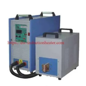
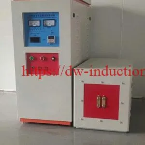
The reference HLQ installation uses the DW-UHF-6kW-III class of induction heating power supply with a remote workhead (a 140 × 90 × 90 mm handpiece) feeding a single application-specific coil. The remote workhead is what makes the cell practical: the power electronics stay at the rear of the bench while the coil and the operator are at the front, so the operator works at the station instead of walking to the machine.
TheDW-UHF-6KW-III handheld induction heater is a portable, air-cooled unit that runs from single-phase 220 V. It is a genuinely deployable cell: a 25 kg source, a small handpiece and one coil will anneal casings at production rate on a bench, in a reload room, or as a standalone station on a production line.
Key Applications
- Annealing brass ammunition casings — the published HLQ application. Relieves the work hardening introduced by drawing and forming so the case returns to a ductile condition, and can be done as a check on whether a case has been over-worked.
- Stress relief before deep drawing — restoring ductility in brass tube, strip and wire so a subsequent forming operation does not crack or tear the material.
- Intermediate anneal between cold-working stages — the classic sheet-metal route, where each anneal resets the material for the next reduction.
- Annealing brass wire and rod — continuous or in-line annealing before a drawing or bending operation. HLQ publishes a separate high-power continuous wire case at 842 °F (450 °C), 300 kHz, running at 15 m/min with a DW-UHF-60kW system.
- Annealing brass tube, fittings and connectors — softening after forming, and preparing a joint for a following brazing step.
- Pre-brazing preparation — bringing a brass assembly to a uniform, verified temperature before the brazing alloy is applied.
- Annealing non-ferrous fasteners and fittings where a flame anneal risks scorching, discolouring or distortion.
For the full process family, see the induction annealing technology overview and the basics of induction heating work.
Suitable Materials
Published case — brass ammunition casings
| Parameter | Part size A | Part size B |
|---|---|---|
| Part length | 1.682 in (42.7 mm) | 0.929 in (23.5 mm) |
| Target temperature | 750 °F (399 °C) | 750 °F (399 °C) |
| Time to target | 0.6 s | 0.6 s |
| Power setpoint | Full power | Reduced to 45% to prevent overheating |
| Coil | Single application-specific coil used for both sizes | |
| Annealed region | Approx. 60% of part length, measured from the open end | |
| Verification | Tempilaq temperature-indicating paint applied inside the case neck | |
Brass grades and their annealing windows
Brass annealing temperature is set by the zinc content, because zinc content governs the phase structure and the temperature at which zinc begins to leave the alloy. The windows below are the published industry ranges for common grades; confirm against your own specification and acceptance criteria.
| Brass grade | Nominal composition | Published annealing range | Notes |
|---|---|---|---|
| Cartridge brass C26000 (CW505L) | Cu 68.5–71.5%, balance Zn (~30%) | 425–675 °C | Melting range 916–955 °C (1680–1750 °F). The most widely quoted window for brass. Upper end of the range requires close control of holding time to limit zinc loss |
| Muntz metal C28000 | Cu 60.5–63.5%, balance Zn (~40%) | 425–600 °C | Alpha-beta structure; the alpha phase is the primary target because phase transformation complicates the response |
| H62 alpha brass | Cu ~62%, balance Zn (~38%) | 450–600 °C | Single-phase alpha brass. Note that Chinese and international grade cross-references for H62 differ — verify against composition limits, not summary tables |
| Red brass C23000 | Cu ~85%, Zn ~15% | 550–700 °C | Low zinc content permits a higher target |
| Stress relief only | Any of the above | 200–250 °C for ~2 h (per EN 12164 ED.2016) | Relieves residual stress without full recrystallisation |
Two limits that shape every brass annealing job
- Zinc volatilisation. Zinc begins to vaporise out of brass at roughly 550–650 °C (1020–1200 °F). Sustained exposure permanently weakens the alloy and alters its properties. Where a specification permits the upper end of a range, it is holding time and atmosphere that keep zinc loss in check — which is exactly what a controlled induction cycle gives you.
- Conductivity drives coupling. Brass is a poorer electrical conductor than copper, so it couples less strongly to the coil and needs a different power setpoint than a copper part of the same size. Cartridge brass C26000 is published at 28 %IACS and C28000 at ≥23 %IACS — against 100 %IACS for pure copper. This is why the recipe is per material, not per part size alone.
Typical ammunition-case annealing is carried out in the 371–427 °C (700–800 °F) band, which is comfortably below the zinc-loss zone and consistent with the 750 °F target used in the published HLQ case.
Working Principle

High-frequency alternating current flows from the DW-UHF-6kW-III power supply into the remote workhead, which feeds the application-specific induction coil positioned around the brass casing.
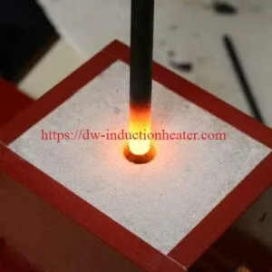
The coil’s alternating magnetic field links the brass and induces circulating eddy currents in the casing wall. Resistance in the current path converts that energy into heat, generatedinside the workpiece rather than transferred to it from outside. The casing therefore heats rapidly and from within — the opposite of a torch, where the outside surface is always hottest.
Frequency determines how deep the induced current penetrates. At the UHF band used here, the skin depth in brass is shallow, so the heat concentrates close to the surface and the heated band is short and well defined. That is what makes it possible to anneal a defined zone on a 42.7 mm casing and leave the rest of it untouched.
Coil position defines where that band falls. In the published case the annealed zone covers approximately 60% of the part length measured from the open end — the neck and shoulder region where work hardening concentrates and where ductility matters most. A fixed stop or jig is what makes that zone repeatable.
Power setpoint controls how fast the target is reached. The smaller casing has far less thermal mass than the larger one, so it is run at reduced power — in the published case, 45% — to reach the same 750 °F in the same 0.6 seconds without overshooting. Because the process is entirely electrical and the coil does not move, the result is repeatable part to part.
For the underlying physics, read the basics of induction heating work.
Technical Specifications
DW-UHF-6KW-III — published specifications
| Item | Published value |
|---|---|
| Model | DW-UHF-6KW-III (UHF series) |
| Cooling | Air-cooled |
| Output power | 6.6 kW |
| Oscillation frequency | 500–1100 kHz (product page). Application notes on the same unit state 300–500 kHz — confirm the configured band |
| Input supply | Single-phase 220 V, 50–60 Hz |
| Input current | 5–30 A |
| Inverter technology | Third-generation IGBT |
| Control modes | Constant-current or constant-power selectable |
| Duty cycle | 100% |
| Quench capability | Quench depth controllable below 1 mm |
| Weight | 25 kg |
| Main unit dimensions | 520 × 240 × 500 mm |
| Handpiece dimensions | 140 × 90 × 90 mm |
| Stated applications | Annealing, brazing of small parts, quick hardening, shallow-case hardening, diamond-blade segment brazing, eyeglass-frame brazing, jewellery and watchcase brazing, electronics brazing, stainless strip annealing, copper-to-copper pipe brazing |
DW-UHF series — published model specifications
| Model | Rated power | Input current | Oscillation frequency | Input supply | Duty cycle |
|---|---|---|---|---|---|
| DW-UHF-3.2KW | 3.2 kW | 13 A | 1.1–2.0 MHz | Single-phase 220 V ±10% | 100% |
| DW-UHF-4.5KW | 4.5 kW | 20 A | 1.1–2.0 MHz | Single-phase 220 V ±10% | 100% |
| DW-UHF-045T | 4.5 kW | 20 A | 1.1–2.0 MHz | Single-phase 220 V ±10% | 100% |
| DW-UHF-045L | 4.5 kW | 20 A | 1.1–2.0 MHz | Single-phase 220 V ±10% | 100% |
| DW-UHF-6.0KW | 6.0 kW | 28 A | 1.1–2.0 MHz | Single-phase 220 V ±10% | 100% |
| DW-UHF-06A | 6.0 kW | 28 A | 1.1–2.0 MHz | Single-phase 220 V ±10% | 100% |
| DW-UHF-6KW-B | 6.0 kW | 28 A | 1.1–2.0 MHz | Single-phase 220 V ±10% | 100% |
| DW-UHF-6.0KW-I | 6.0 kW | 28 A | 1.1–2.0 MHz (variant I) | Single-phase 220 V | 100% |
| DW-UHF-6.0KW-II | 6.0 kW | 28 A | 200–700 kHz (variant II) | Single-phase 220 V | 100% |
| DW-UHF-6.0KW-III | 6.0 kW | 28 A | 500–1100 kHz (variant III) | Single-phase 220 V | 100% |
| DW-UHF-10KW | 10 kW | 15 A | 100–500 kHz | 3 × 380 V ±10% | 100% |
| DW-UHF-20KW | 20 kW | 30 A | 50–250 kHz | 3 × 380 V ±10% | 100% |
| DW-UHF-30KW | 30 kW | 45 A | 50–200 kHz | 3 × 380 V ±10% | 100% |
| DW-UHF-40KW | 40 kW | 60 A | 50–200 kHz | 3 × 380 V ±10% | 100% |
| DW-UHF-60KW | 60 kW | 90 A | 50–150 kHz | 3 × 380 V ±10% | 100% |
DW-HF series — published model specifications
| Model | Max input power | Max input current | Frequency | Input voltage | Duty cycle |
|---|---|---|---|---|---|
| DW-HF-04 (4KW-A) | 4 kVA | 15 A | 100–250 kHz | Single-phase 220 V | 80% |
| DW-HF-15KW-A / -B | 15 kVA | 32 A | 30–100 kHz | Single-phase 220 V | 80% |
| DW-HF-25KW-A / -B | 25 kVA | 23 A | 20–80 kHz | 3-phase 380 V ±10% | 100% |
| DW-HF-35KW-B | 35 kVA | 51 A | 20–80 kHz | 3-phase 380 V | 100% |
| DW-HF-45KW-B | 45 kVA | 68 A | 20–80 kHz | 3-phase 380 V | 100% |
| DW-HF-60KW-B | 60 kVA | 105 A | 20–80 kHz | 3-phase 380 V | 100% |
| DW-HF-80KW-B | 80 kVA | 130 A | — | 3-phase 380 V | 100% |
| DW-HF-90KW-B | 90 kVA | 160 A | — | 3-phase 380 V | 100% |
| DW-HF-120KW-B | 120 kVA | 200 A | — | 3-phase 380 V | 100% |
All DW-HF units use IGBT inverter technology; the 25 kW and larger models support three-phase supply for continuous (100%) duty cycle. The 15 kW frequency band is listed as 30–100 kHz on some English pages and 30–80 kHz on others — confirm before ordering.
Temperature verification — Tempilaq
| Item | Specification |
|---|---|
| Product | Tempilaq temperature-indicating liquid paint |
| Available ratings | 43 ratings from 175 °F to 1900 °F (79–1038 °C) |
| Rating used in this case | 750 °F (399 °C), part no. 024423 |
| Accuracy | Within ±1% of rated temperature (≈ ±7.5 °F at the 750 °F rating) |
| Method | Applied to a dry, smooth surface; the film liquefies and turns translucent at the rated temperature and re-solidifies as a permanently different, irreversible mark |
| Application in this case | Brushed inside the case neck to confirm the target temperature |
| Important limitation | Confirms that a surface temperature was reached — it does not indicate dwell time or temperature uniformity |
| Solvent | Green Label Thinner only |
Recommended Model Selection
Model choice for brass annealing is driven by three things: the mass of brass to be heated per cycle, the length of the annealed zone, and the target temperature relative to the zinc-loss zone. Frequency follows from how the heat should be distributed; power follows from how much energy must be delivered in the available cycle time.
| Application profile | Source class | Frequency band | Supply | Coil and notes |
|---|---|---|---|---|
| Small brass casings, fittings and connectors; bench or single-station work; one coil across a size range | DW-UHF-6KW-III (or -6.0KW-II / -6.0KW-I) | 500–1100 kHz published; 300–500 kHz cited in application notes | Single-phase 220 V | Single application-specific coil; power setpoint adjusted per part size |
| Micro-soldering, fine connectors, precision small parts | DW-UHF-3.2KW / 4.5KW / 045T / 045L class | 1.1–2.0 MHz | Single-phase 220 V | Application-specific coil, or a portable induction brazing unit |
| Larger brass assemblies, tube and fittings; brazing brass at 750 °C | DW-UHF-20KW class | 150–500 kHz | 3 × 380 V | Multi-turn helical coil with a remote heat station — see induction brazing of brass fittings |
| Continuous or in-line brass and copper wire annealing | DW-UHF-60KW class | 50–150 kHz | 3 × 380 V | Twelve-turn helical coil with a ceramic tube inside the coil to isolate the wire — see the published 842 °F, 300 kHz, 15 m/min continuous wire case |
| Heavy brass sections and long heated zones | DW-HF-25KW to DW-HF-120KW class | 20–100 kHz | 3 × 380 V | Deep penetration at low frequency for thick sections |
Selection rule of thumb. If one brass part can be brought to target in well under a second or two and the annealed zone is short, the DW-UHF-6KW-III class with a remote workhead is the starting point. Step up to the DW-UHF 10–60 kW models when the heated zone grows beyond a single coil length, when the material mass per cycle rises, or when the cell must run two shifts — all published DW-UHF models are rated for 100% duty cycle. See the IGBT induction heating machine page for the full induction heating system configurations.
Process Workflow

- Select the recipe. Match the brass grade, the part size and the target temperature to a power setpoint. Grade and size both change the answer, because conductivity governs coupling and mass governs the energy required.
- Apply Tempilaq paint. Brush the 750 °F rated paint into the case neck. Do this before the part goes near the coil — the mark has to be on the part, not on a coupon.
- Load the casing. Place the casing into the coil with the open end first, so the annealed zone falls on the neck and shoulder.
- Set the coil position. Adjust until the annealed zone covers approximately 60% of the part length from the open end. Use a fixed stop or jig so this is identical every cycle.
- Set the power. Full power for the 1.682 in case; reduce to 45% for the 0.929 in case to prevent overheating.
- Energise. Switch on the source. Heating is hands-free once started.
- Heat to target. The eddy-current heating zone brings the casing to 750 °F (399 °C) in 0.6 seconds.
- Confirm the target. The Tempilaq film liquefies and stays translucent — that is your proof the temperature was reached.
- Cool and unload. Let the casing cool, then remove it. Do not quench unless a specific hardness result calls for it.
- Inspect and run. Check the annealed zone, then reset for the next part. Because coil position and parameters are fixed, the cycle repeats identically.

Putting the source at the rear of the cell and the remote workhead at the operator position keeps the leads off the operator side and keeps the mains inlet away from the hot work area. Fixed coil stops in front of the station are what make the 60% annealed zone repeatable. The paint station is deliberately within reach — verification is the step that gets skipped when it is inconvenient, and skipping it is how a 750 °F job quietly becomes a 900 °F job with zinc loss. There is no open flame at the station. For the general case, see induction heating vs flame heating.
Common Problems and Solutions
| Symptom | Likely cause | Action |
|---|---|---|
| Small casing overheats or discolours while the large one is fine | Full power applied to a much smaller thermal mass | Reduce the power setpoint for the smaller part. In the published case, 45% power brings the 0.929 in casing to the same 750 °F in the same 0.6 s |
| Paint does not liquefy, but the part was clearly hot | Paint applied to the wrong surface, or a rating that does not match the target | Confirm the rating matches the target (750 °F part no. 024423) and that the paint was on the part, in the heated zone, not on a coupon |
| Paint liquefies but the part is not soft enough | Temperature was reached but dwell time was too short | Tempilaq confirms peak temperature only, not soak. Add hold time at temperature to equalise the section |
| Annealed zone is in the wrong place on the part | Casing loaded backwards, or the coil stop has been knocked | Load with the open end first. Use a mechanical stop so the 60% zone is set by the jig and not by eye |
| Zone position shifts between parts | Casings vary in length, so a fixed stop gives a variable percentage | Set the stop by the case length for the size being run, or use a length-indexed fixture |
| Part discolours, dulls or smokes | Target above the zinc volatilisation zone of roughly 550–650 °C, or soak too long | Confirm the target against the grade’s annealing window. Above the zinc-loss band, holding time and atmosphere control how much zinc leaves the alloy |
| Cycle-to-cycle results vary | Coil position, recipe or part orientation not standardised | Fix the coil position with a stop, lock one recipe per grade and size, and confirm against the 0.6 s reference |
| Coil or handpiece runs hot | Duty beyond the design coil loading, or the part is being over-coupled | Check the coil is sized for the part, and reduce the setpoint if the coupling is stronger than the design assumes |
| Source trips or behaves erratically | Mains supply or input current outside the published envelope | Confirm single-phase 220 V at 50/60 Hz and the rated5–30 A input current before sizing the breaker or the circuit |
| Annealed part is annealed everywhere, not in a zone | Coil is longer than intended, or the part is smaller than the coil was designed for | Re-evaluate the coil for the part size. The 60% zone is a design outcome of the coil geometry and the part length together |
Engineering Selection Guide
Work through these five questions in order when specifying a brass annealing cell.
- What is the target condition? Full anneal (recrystallisation and ductility recovery) or stress relief only at 200–250 °C for ~2 hours per EN 12164 ED.2016. This sets the temperature band, and the band decides whether you are anywhere near the zinc-loss zone.
- What is the grade? Cartridge brass, Muntz metal, H62 alpha brass and red brass have different published annealing windows — 425–675 °C, 425–600 °C, 450–600 °C and 550–700 °C respectively. Grade is the first number you need, and it is not interchangeable with part size.
- How much brass must be heated per cycle? This drives power. Small casings on a single coil length are the DW-UHF-6KW-III class. Longer zones or heavier sections move you to DW-UHF 10–60 kW on three-phase supply, or to the DW-HF low-frequency range for thick sections.
- What length of annealed zone is required? In the published case, 60% of the part length from the open end. The coil is designed around that figure and around the part length, so this decision drives coil geometry, and coil geometry drives everything else.
- What is the production rate and the duty cycle? A sub-second cycle and a two-shift requirement are very different cells. All published DW-UHF models are 100% duty cycle; the DW-HF-04 and15 kW models are published at 80%.
Specification checklist before release. Brass grade and the required hardness, tensile or ductility outcome; part size range and wall thickness; target temperature and soak time; annealed zone length and how it is located on the part; parts per hour; available supply (single-phase 220 V or three-phase 380 V); coil stand-off and jig concept; whether the cell runs attended or unattended; and the verification method you will accept — paint, thermocouple, or a hardness check on the finished part.
Advantages and Limitations
Advantages
- Extremely fast. 0.6 seconds to 750 °F on both a 1.682 in and a 0.929 in casing, against the minutes a torch or a small batch furnace needs per part.
- One coil across the size range. A single application-specific coil annealed both case sizes in the published trial, which removes tooling changeover and a source of error.
- Local and controlled. The annealed zone is defined by the coil, so the rest of the part is not thermally soaked — a decisive advantage on a thin-walled casing.
- Repeatable. Fixed coil position, fixed recipe and a0.6 second cycle give the same thermal history on every part, which is what makes the process auditable.
- Flameless and hands-free. No open flame at the station and no operator skill needed once the cycle is running.
- Verified in the loop. Temperature-indicating paint gives an irreversible, per-part record that the target was actually reached.
- Small and deployable. 25 kg, 520 × 240 × 500 mm, single-phase 220 V — a bench-capable cell rather than a machine that needs a room.
- 100% duty cycle across the published DW-UHF range.
Limitations
- The coil is application-specific. It was designed for this part range. A different diameter, a different length or a much larger annealed zone means a new coil, and the coil is a wear item over time.
- Brass couples less strongly than copper. At roughly 23–28 %IACS against 100 %IACS for copper, the power setpoint must be reworked for the material, not carried over from a copper recipe.
- Temperature-indicating paint confirms a peak, not a soak. It makes no statement about dwell time or uniformity, so it cannot by itself qualify a cycle.
- Zinc loss is not reversible. Above roughly 550–650 °C, or with excessive holding time, zinc leaves the alloy and the part is permanently weakened. The recipe has to keep the target and the soak inside the grade’s window.
- Power setpoint is per part. The published case already needed a different setpoint for the smaller casing. A mixed-size production run means multiple recipes on the same cell.
- Thin walls and small features are delicate. A very small or very thin part can overheat at a setpoint that is correct for a larger one — the 45% figure in the published case is the direct evidence of this.
- Hot-part handling still needs a plan. The process is flameless, not cool — parts leave the coil at temperature and need somewhere to cool safely.
- Target temperatures are case data, not a specification. The 750 °F figure comes from one application. Confirm it against your own grade, section size and acceptance criteria.
Why Choose HLQ?
HLQ (DW Induction Heating, Dongguan, Guangdong) builds and supports a full frequency ladder rather than a single machine class: DW-UHF for ultra-high-frequency work from 3.2 kW to 60 kW, DW-HF and DW-MF for medium- and low-frequency heavy work, and a full solid-state line for continuous production.
- IGBT solid-state inverters with selectable constant-current or constant-power control, running at 100% duty cycle across the published range.
- Remote workhead architecture, which is what makes the brass cell practical: the operator works at the front of the bench while the electronics stay at the rear.
- A published application library rather than catalogue pages. Real parameters across annealing, brazing, hardening, preheating, powder coating and paint stripping — including brass casings, brass fittings, brass pipe and continuous wire.
- Application-specific coil engineering, as in the single coil developed to anneal both the 1.682 in and 0.929 in casings.
- Scale options from one platform — the same DW-UHF architecture covers a25 kg bench unit and a 60 kW continuous wire line.
- A multilingual technical site and direct engineering contact, so coil and recipe questions reach the people who built the machine.
For the wider equipment range, start from the induction heating power supply range and the energy-efficient induction heating overview. If your brass part is a wire rather than a casing, see the published continuous annealing of copper and brass wire application at 842 °F and 15 m/min.
6 Core FAQs
1. What temperature do you anneal brass to?
In the published HLQ brass casing application, the target is 750 °F (399 °C), and both case sizes reached it in 0.6 seconds. Typical ammunition-case annealing is carried out in the 371–427 °C (700–800 °F) band. Note that common brasses have no useful precipitation-hardening response — annealing is used to relieve work hardening and restore ductility, and above roughly 550–650 °C zinc begins to volatilise out of the alloy and permanently weaken it, so confirm your target against the grade’s window.
2. How long does it take to anneal a brass part?
0.6 seconds for both sizes tested — the 1.682 in (42.7 mm) and the 0.929 in (23.5 mm) brass casings both reached 750 °F in the same time. The smaller casing does not take longer to reach temperature because it was run at a reduced power setpoint, so it did not overshoot on the way.
3. Which induction heating machine is used for brass annealing?
A DW-UHF-6kW-III air-cooled solid-state system with a remote workhead feeding a single application-specific induction coil. Published ratings for the unit: 6.6 kW output,500–1100 kHz oscillation, single-phase 220 V at 50/60 Hz, 5–30 A input, 25 kg, main unit 520 × 240 × 500 mm and handpiece 140 × 90 × 90 mm. Note that application notes on the same unit state 300–500 kHz, so confirm the configured frequency band when ordering.
4. Do you need a different coil for different brass part sizes?
Not in this application. The same single coil annealed both the 1.682 in and the 0.929 in casings in the published trial, which means one coil design, one power supply and one set of tooling across the range. What changes is the power setpoint — full power for the larger casing, reduced to 45% for the smaller one to prevent overheating. A materially different diameter, a different annealed-zone length or a different target temperature would justify a re-designed coil.
5. How is the annealing temperature verified?
With Tempilaq temperature-indicating paint brushed into the case neck before heating. The film liquefies and turns translucent when the surface reaches its rated temperature and re-solidifies as a permanently different, irreversible mark. Tempilaq is published at±1% of rated temperature — roughly ±7.5 °F at the 750 °F rating — and the 750 °F version is part number 024423. The important limitation is that it confirms that a temperature was reached, not dwell time or uniformity, so it should be combined with a soak and a hardness or ductility check on the finished part.
6. Is induction annealing suitable for brass, and how does it compare with a flame anneal?
Yes. Brass is electrically conductive and couples efficiently to an induction coil, and the published application anneals brass casings at 0.6 seconds per part with heat confined to a defined zone. Compared with a flame anneal, the advantages are speed, control and safety: the heat is generated inside the part rather than transferred from outside, so the heat zone is defined by the coil and the rest of the casing is not thermally soaked; the cycle is repeatable part to part; and there is no open flame at the station. The trade-off is that the coil is application-specific and the power setpoint must be reworked per material and per size.