Induction Annealing Shaft End
Induction Annealing of Shaft Ends: 1350°F in 20 Seconds with a DW-UHF-10 kW
Quick Answer
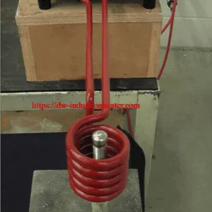
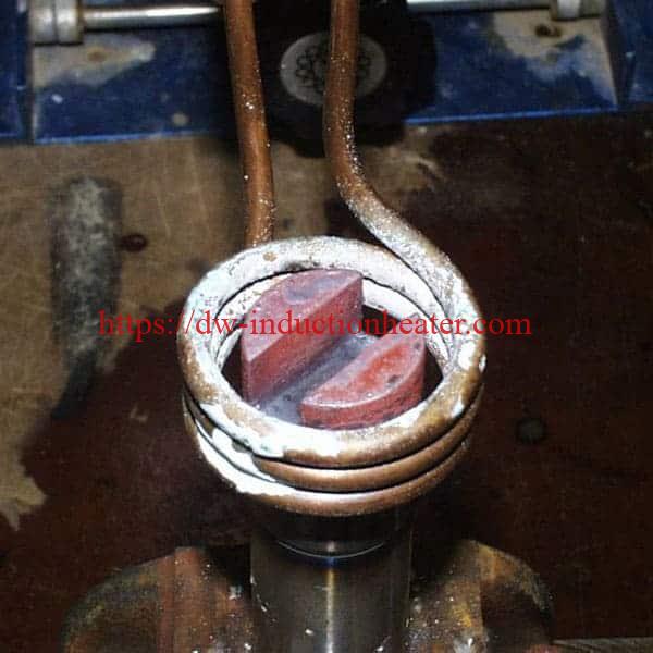
Induction annealing of a shaft end heatsonly the end of a steel shaft to a controlled temperature so it can be machined cleanly afterwards — without a flame, a furnace, or any risk to the rest of the component. HLQ’s reference application anneals the end of a steel hydraulic motor shaft using a DW-UHF-10 kW induction heating system running at 300 kHz, with a remote workhead containing one 1.0 µF capacitor driving a custom three-turn helical coil.
The published case data: a 0.75 in (19 mm) diameter steel rod, 6 in (152.4 mm) long, with a keyway at the end, reached 1350 °F (732 °C) in 20 seconds. Only the shaft end sits inside the coil, so the remainder of the rod never sees the anneal temperature. The stated benefits are high efficiency and low energy cost, precise, controllable heat placement, a faster production cycle, and consistent, repeatable results.
One engineering point matters more than any other on this page: 732 °C sits essentially at the eutectoid Ac1 of 723 °C, so whether the result is a full intercritical anneal or a sub-critical stress relief depends entirely on the carbon content of the shaft.
Table of Contents
- Quick Answer
- What is the Induction Annealing Machine for Shaft Ends?
- Key Applications
- Suitable Materials
- Working Principle
- Technical Specifications
- Recommended Model Selection
- Process Workflow
- Common Problems and Solutions
- Engineering Selection Guide
- Advantages and Limitations
- Why Choose HLQ?
- 6 Core FAQs
What is the Induction Annealing Machine for Shaft Ends?
A shaft-end annealing station is an induction heating cell built around a solid-state power supply, a remote workhead and a purpose-designed helical coil. The shaft end is placed inside the coil, high-frequency alternating current induces eddy currents in the steel, and the end heats from within to a set target temperature. The process is non-contact, flameless and geometrically localised — heat is applied only where the coil sits, so the shank, the seal journal and everything else on the shaft never see the anneal temperature.
That last point is the commercial argument. A flame anneal or a furnace bath heats the whole component: the entire shaft is heated, and every surface on it has to be cleaned, inspected and re-machined afterwards. An induction coil applies heat to a defined length, so the rest of the part is left alone. It is also why the coil, not a temperature setting, is what defines the annealed zone — the zone is a geometric consequence of the coil, which makes it repeatable from part to part.
The reference HLQ installation uses the DW-UHF-10 kW class of induction heating power supply with a remote workhead containing one 1.0 µF capacitor feeding a three-turn helical coil. The remote workhead is what makes the cell practical: the power electronics stay at the rear of the bench while the coil and the operator are at the front.
On the same platform, HLQ runs the induction heating of wire for hot heading at the identical 1350 °F (732 °C) target on a DW-UHF-6 kW source — the same physics, a different workpiece and a different coil. For the general process family, see the induction annealing overview.
Key Applications
- Annealing a shaft end before machining — the published HLQ application. Softens the end of a steel hydraulic motor shaft so the keyway and the end features can be cut without tearing or work-hardening the surface.
- Stress relief before machining or fitting — relieving residual stress in a turned or ground shaft end so it stays dimensionally stable after machining and does not move on assembly.
- Localised end heating for hot forming — heating only the forming zone of a bar or axle end rather than the whole billet. HLQ’s induction forging and hot forming range covers full heating of billets and bars alongside localised heating of pipe ends, axle ends and bar ends.
- Heating steel for hot heading — bringing a wire or a cold-formed part to 1350 °F (732 °C) so it can be upset or headed. HLQ’s published wire case runs 12 wires at a time at 130 parts per minute.
- Pre-brazing preparation of a shaft end — bringing a steel shaft end to a uniform, verified temperature before a silver-solder or brazing step. See the induction brazing of a carbide shaft application.
- Thermal expansion for shrink fitting — heating a shaft or gear for interference assembly. This is a different process from annealing but the same hardware; see induction shrink fitting of shaft gears.
- Localised hardening of journals or shoulders — where a shaft needs a hard surface on one feature and a soft core elsewhere. For fully automated work, see the induction shaft hardening machine for pins, shafts and rods.
Suitable Materials
Published case — steel hydraulic motor shaft
| Parameter | Value |
|---|---|
| Objective | Anneal the end of a steel hydraulic motor shaft prior to machining |
| Workpiece | 0.75 in (19 mm) diameter steel rod, 6 in (152.4 mm) long, with a keyway at the end |
| Target temperature | 1350 °F (732 °C) |
| Time to target | 20 seconds |
| Frequency | 300 kHz |
| Equipment | DW-UHF-10 kW induction heating system |
| Workhead | Remote workhead containing one 1.0 µF capacitor |
| Coil | Custom-designed three-turn helical coil |
| Method | Shaft end placed in the coil, power applied for 20 seconds until the steel turns red hot |
| Stated benefits | High efficiency and low energy cost; precise, controllable heat placement so only the region needing anneal is heated; faster production cycle; consistent, repeatable results |
Critical temperatures — what 732 °C actually does to your steel
This is the single most useful table on the page. Ac1 is the temperature at which austenite begins to form. Heat a hypoeutectoid carbon steel below its Ac1 and no allotropic transformation occurs — the ferrite–pearlite structure from prior working is retained, and only residual stress, dislocation substructure and carbide spheroidization change. Heat it between Ac1 and Ac3 and you get partial austenitization: an intercritical anneal.
| Carbon content | Ac1 | Ac3 | Result of a 732 °C (1350 °F) hold |
|---|---|---|---|
| 0.2 % C | ~820–850 °C | ~870–900 °C | Sub-critical. Stress relief and recrystallisation only — no austenitization |
| 0.4 % C | ~780 °C | ~815 °C | Sub-critical. Stress relief and recrystallisation only |
| 0.6 % C | ~755 °C | ~765 °C | Just below Ac1 — sub-critical stress relief |
| 0.8 % C (eutectoid) | ~723–740 °C | — | Intercritical. Partial austenitization at732 °C, then full anneal on cooling |
Practical consequence. The published 1350 °F target produces a full intercritical anneal on a eutectoid steel and a sub-critical stress relief on anything below roughly 0.7 % C. If your process depends on the difference, specify the target against the grade rather than reusing the published number. For reference, stress-relief annealing of most carbon steel grades is typically carried out at 550–650 °C, deliberately below Ac1, and spheroidizing uses 500–650 °C with long holds of 5–20 hours — the latter is generally limited to steel below about 0.8 % C, and below 0.4 % C the result can be too soft and gum up cutting tools.
Reading the heat colour
The published case confirms the result visually: the steel “turns red hot”. On the Chapman heat-colour scale, 1350 °F falls in the dark red band. This is a useful sanity check on the cycle, but it is a check and not a measurement — published guidance stresses that these colours must be judged in dim or shaded conditions, because in bright light a piece of steel can look a full colour grade hotter than it really is.
| Heat colour | Temperature range |
|---|---|
| Black red | 799–1,100 °F |
| Very dark red | 1,100–1,299 °F |
| Dark red | 1,300–1,497 °F — the 1350 °F target sits here |
| Cherry red | 1,498–1,598 °F |
| Light cherry red | 1,599–1,798 °F |
| Orange | 1,799–1,998 °F |
| Yellow | 1,999–2,296 °F |
Do not use colour to qualify a cycle. It confirms nothing about dwell time or temperature uniformity. Verify with a pyrometer or temperature-indicating paint, and confirm the result on the finished part with a hardness check.
Working Principle

High-frequency alternating current flows from the DW-UHF-10 kW power supply into the remote workhead, where a single 1.0 µF capacitor forms the resonant tank circuit. The workhead feeds a three-turn helical coil positioned over the end of the shaft.
The coil’s alternating field links the steel and induces circulating eddy currents in the shaft itself. Resistance in the current path converts that energy into heat, generated inside the workpiece rather than transferred to it from outside. The end therefore heats rapidly and from within — the opposite of a torch, where the outside surface is always hottest and the heat has to conduct inwards.
Frequency sets how deep the induced current penetrates. At 300 kHz the skin depth in steel is shallow, so heat is concentrated close to the surface and the heated band is short and well defined. That is what makes it possible to anneal a defined zone on one end of a 152.4 mm rod while leaving the other 90 mm untouched.
Coil position defines where that band falls, and the band is short by design — the heat placement is a geometric consequence of the coil, not a control setting. This is the core engineering difference between induction annealing of a shaft end and a furnace anneal: the coil is the tooling that defines the process.
Time and power together set how quickly the target is reached. In the published case, 20 seconds at the 10 kW source brings a 19 mm diameter steel end to 1350 °F. Because the process is entirely electrical and the coil does not move, the result repeats from shaft to shaft.
For the underlying physics, read the basics of induction heating work.
Technical Specifications
DW-UHF-10KW — published specifications
| Item | Published value |
|---|---|
| Model | DW-UHF-10KW (UHF series) |
| Output power | 10 kW |
| Input supply | 3-phase380 V ±10%, 50–60 Hz |
| Oscillation frequency | 50–300 kHz or 100–500 kHz, configurable. The published case runs at 300 kHz |
| Input current | 3–15 A (max 15 A) |
| Inverter technology | Third-generation IGBT |
| Control modes | Constant-current or constant-power selectable |
| Duty cycle | 100% |
| Hardening depth capability | Controllable below 1 mm |
| Weight | 30 kg (main unit). The feature list on the same page states “only 25KG” — confirm the shipping weight |
| Main unit dimensions | 570 × 260 × 500 mm |
| Stated applications | Quick quenching, shallow-depth hardening, brazing of small workpieces, heating tiny parts, diamond blade segment brazing, carbon steel / PCBN blade brazing, watchcase annealing, bulb filament brazing, precision mechanical part heating, stainless steel strip annealing |
DW-UHF series — published model specifications
| Model | Rated power | Input current | Oscillation frequency | Input supply | Duty cycle |
|---|---|---|---|---|---|
| DW-UHF-3.2KW | 3.2 kW | 13 A | 1.1–2.0 MHz | Single-phase 220 V ±10% | 100% |
| DW-UHF-4.5KW | 4.5 kW | 20 A | 1.1–2.0 MHz | Single-phase 220 V ±10% | 100% |
| DW-UHF-045T | 4.5 kW | 20 A | 1.1–2.0 MHz | Single-phase 220 V ±10% | 100% |
| DW-UHF-045L | 4.5 kW | 20 A | 1.1–2.0 MHz | Single-phase 220 V ±10% | 100% |
| DW-UHF-6.0KW | 6.0 kW | 28 A | 1.1–2.0 MHz | Single-phase 220 V ±10% | 100% |
| DW-UHF-06A | 6.0 kW | 28 A | 1.1–2.0 MHz | Single-phase 220 V ±10% | 100% |
| DW-UHF-6KW-B | 6.0 kW | 28 A | 1.1–2.0 MHz | Single-phase 220 V ±10% | 100% |
| DW-UHF-6.0KW-I | 6.0 kW | 28 A | 1.1–2.0 MHz (variant I) | Single-phase 220 V | 100% |
| DW-UHF-6.0KW-II | 6.0 kW | 28 A | 200–700 kHz (variant II) | Single-phase 220 V | 100% |
| DW-UHF-6.0KW-III | 6.0 kW | 28 A | 500–1100 kHz (variant III) | Single-phase 220 V | 100% |
| DW-UHF-10KW | 10 kW | 15 A | 100–500 kHz | 3 × 380 V ±10% | 100% |
| DW-UHF-20KW | 20 kW | 30 A | 50–250 kHz | 3 × 380 V ±10% | 100% |
| DW-UHF-30KW | 30 kW | 45 A | 50–200 kHz | 3 × 380 V ±10% | 100% |
| DW-UHF-40KW | 40 kW | 60 A | 50–200 kHz | 3 × 380 V ±10% | 100% |
| DW-UHF-60KW | 60 kW | 90 A | 50–150 kHz | 3 × 380 V ±10% | 100% |
| DW-UHF-100KW | 100 kW | 145 A | 50–150 kHz | 3 × 380 V | 100% |
DW-HF series — published model specifications
| Model | Max input power | Max input current | Frequency | Input voltage | Duty cycle |
|---|---|---|---|---|---|
| DW-HF-04 (4KW-A) | 4 kVA | 15 A | 100–250 kHz | Single-phase 220 V | 80% |
| DW-HF-15KW-A / -B | 15 kVA | 32 A | 30–100 kHz | Single-phase 220 V | 80% |
| DW-HF-25KW-A / -B | 25 kVA | 23 A | 20–80 kHz | 3-phase 380 V ±10% | 100% |
| DW-HF-35KW-B | 35 kVA | 51 A | 20–80 kHz | 3-phase 380 V | 100% |
| DW-HF-45KW-B | 45 kVA | 68 A | 20–80 kHz | 3-phase 380 V | 100% |
| DW-HF-60KW-B | 60 kVA | 105 A | 20–80 kHz | 3-phase 380 V | 100% |
| DW-HF-80KW-B | 80 kVA | 130 A | — | 3-phase 380 V | 100% |
| DW-HF-90KW-B | 90 kVA | 160 A | — | 3-phase 380 V | 100% |
| DW-HF-120KW-B | 120 kVA | 200 A | — | 3-phase 380 V | 100% |
All DW-HF units use IGBT inverter technology; the 25 kW and larger models support three-phase supply for continuous (100%) duty cycle. The 15 kW frequency band is listed as 30–100 kHz on some English pages and 30–80 kHz on others — confirm before ordering.
DW-HF-45KW — published specification detail
| Item | Value |
|---|---|
| Max oscillation power | 45 kVA |
| Operating frequency | 30–80 kHz |
| Max input power | 50 kVA |
| Input | 3 × 380 V, 50–60 Hz |
| Oscillation current | 15–90 A |
| Duty cycle | 100% at 30 °C |
| Cooling water | 0.3 MPa, ≥ 6 L/min |
| Weight | 75 kg |
| Main unit dimensions | 550 × 240 × 535 mm |
| Remote extension | 470 × 265 × 440 mm, 2 m cable |
Recommended Model Selection
Model choice for shaft-end work is driven by three things: the mass of steel to be heated per cycle, the length of the annealed zone, and the target temperature relative to the steel’s Ac1. Frequency follows from how deep the heat should penetrate; power follows from how much energy must be delivered in the available cycle time.
| Application profile | Source class | Frequency band | Supply | Published reference |
|---|---|---|---|---|
| Small steel shaft ends, single-station or bench work, localised anneal before machining | DW-UHF-10KW | 50–300 kHz or 100–500 kHz | 3 × 380 V | This application — 19 mm dia × 152.4 mm rod, 1350 °F (732 °C) in 20 s at 300 kHz, three-turn helical coil, remote workhead with one 1.0 µF capacitor |
| Fine wire and small precision parts at the same 1350 °F target | DW-UHF-6KW class | 1.1–2.0 MHz / 200–700 kHz / 500–1100 kHz by variant | Single-phase 220 V | Wire for hot heading — 0.185 in (4.4 mm) steel wire, 141 kHz, top 0.3 in heated in 5 s, two-turn channel coil, 12 wires at a time, 130 parts/min |
| Carbide or tool-steel shaft ends needing brazing rather than annealing | DW-UHF-6KW-III / DW-UHF-10KW class | 300 kHz class | Single-phase 220 V / 3 × 380 V | Carbide shaft to steel tube at 1400 °F, 300 kHz, remote heat station with two 0.66 µF capacitors, 60 s hold |
| Intermittent part annealing on larger sections, deeper heat penetration | DW-HF-25KW to DW-HF-120KW class | 20–100 kHz | 3 × 380 V | DW-HF-45KW at 30–80 kHz for copper tube annealing at 1500 °F (815.5 °C) — 1.625 in × 24 in tube, four-turn helical coil, 7.5 s total, anneal zone 1.5 in from each end |
| Thermal expansion for shrink fitting a gear or bearing onto a shaft | DW-UHF-3.5 / 5 / 7.5 kW class | 151–158 kHz | Single-phase 220 V | Camshaft gears 6 in dia × 2 in thick to 518 °F (steel) and 320 °F (aluminium), remote heat station with one 0.66 µF capacitor |
| Fully automated shaft, pin and rod work needing surface hardening | DW-MF and CNC scanner configurations | Low kHz class | 3 × 380 V | Configured for hardening rather than annealing — a different coil and a different process window |
Selection rule of thumb. If a single shaft end can be brought to target in tens of seconds and the annealed zone is short, the DW-UHF-10KW class with a remote workhead is the starting point. Step up to the DW-UHF 20–100 kW models when the section grows, when the heated zone runs past a single coil length, or when the cell must run two shifts — all published DW-UHF models are rated for 100% duty cycle. See the IGBT induction heating machine page for the full induction heating system configurations.
Process Workflow

- Verify the material. Confirm the steel grade and, critically, its carbon content — because at 732 °C that single number decides whether you are running an intercritical anneal or a sub-critical stress relief.
- Fit the coil. Three-turn helical coil, custom designed for the shaft diameter and the length of zone you need.
- Load the shaft. Shaft end into the coil, with the body of the shaft clear of it. Only the end is in the coil, and that is the entire point of the process.
- Set the target. 1350 °F (732 °C) for the published case. Set it against your grade’s Ac1 and your acceptance criteria, not against the published number alone.
- Set the profile. 300 kHz, the power setpoint, and a 20 second heating time as the starting point.
- Energise. Switch on the DW-UHF-10 kW source. Heating is hands-free once started.
- Heat to target. 20 seconds brings the end to 1350 °F and the steel turns red hot.
- Verify the heat. Check the colour as a sanity check, but verify with a pyrometer or temperature-indicating paint, and confirm the result on the finished part with a hardness check.
- Cool naturally. Let the end cool before handling or machining. Do not quench unless a specific hardness result calls for it.
- Machine the end. Finish the annealed end to final size. The keyway cuts in soft, annealed steel rather than in a work-hardened surface.

Putting the source at the rear of the cell and the remote workhead at the operator position keeps the leads off the operator side and keeps the mains inlet away from the hot work area. A fixed stop in front of the coil is what repeats the same end-in-coil position cycle after cycle — and since the annealed zone is defined by coil position, that stop is the repeatability mechanism. A cooling rack between the anneal and the machining station keeps hot ends off the bench. There is no open flame at the station. For the general case, see induction heating vs flame heating.
Common Problems and Solutions
| Symptom | Likely cause | Action |
|---|---|---|
| Annealed zone is in the wrong place along the shaft | Shaft not seated against the fixed stop, or the stop has moved | Re-seat the shaft against the stop. The zone is defined by coil position, so the stop is the tolerance |
| Zone position varies between shafts | Shafts vary in length, so a fixed stop gives a variable position | Set the stop by length for the batch, or use a length-indexed fixture |
| Heat spreads further along the shaft than expected | Coil too long for the required zone, or the shaft sitting too close to the coil end | Re-specify the coil for the zone length you need. A longer coil heats a longer band — the two are the same decision |
| End reaches temperature but the shaft is still hard to machine | Target was sub-critical for this carbon content, or dwell time was too short | Check the grade against the Ac1 table. A sub-critical hold relieves stress but does not soften the structure; the target or the hold has to change |
| End overheats or the steel burns | Power setpoint too high for the section, or the cycle longer than needed | Reduce the setpoint or the heating time. Watch the heat colour: on the Chapman scale, dark red is 1,300–1,497 °F, and cherry red starts at 1,498 °F |
| Part looks red hot but is not actually at temperature | Colour read in bright light, or the operator reading the wrong part of the shaft | Judge colour in dim light only. Confirm with a pyrometer or temperature-indicating paint before committing the cycle |
| Result varies from shaft to shaft | Coil position, recipe or part orientation not standardised | Fix the coil position with a stop, lock one recipe per grade and diameter, and re-verify against the 20 second reference |
| Coil or workhead runs hot | Duty beyond the design coil loading, or a workhead capacitor mismatch | Check the workhead capacitor against the design — the reference build uses a single 1.0 µF capacitor — and confirm the coil is not over-coupled to the workpiece |
| Keyway tears or the end surface tears during machining | End not sufficiently annealed, or the anneal was not sub-critical enough for the grade | Verify the achieved hardness on the finished part. A sub-critical stress relief at 550–650 °C is the usual target where only machining behaviour matters |
| Supply trips or behaves erratically | Mains supply or input current outside the published envelope | Confirm 3-phase 380 V ±10% at 50/60 Hz and the rated 3–15 A input current before sizing the breaker or the circuit |
Engineering Selection Guide
Work through these five questions in order when specifying a shaft-end annealing cell.
- What is the grade and carbon content? This is the first question, not the last. At 732 °C the result is intercritical for a eutectoid steel and sub-critical below roughly 0.7 % C. If the process depends on softness for machining, the grade sets your target — not the other way round.
- How long is the annealed zone, and where on the shaft? The zone is defined by the coil, so this decides the coil design, and the coil is the most application-specific part of the cell. Plan the zone before anything else.
- What is the mass of steel to be heated per cycle? This drives power. A 19 mm diameter end reaching 732 °C in 20 seconds sits comfortably in the DW-UHF-10KW class. Heavier sections or longer zones move you up the DW-UHF range or down into DW-HF.
- What is the production rate and the duty cycle? A twenty-second cycle at a single operator is a very different cell from a continuous production line. All published DW-UHF models are 100% duty cycle; DW-HF-04 and 15 kW models are published at 80%.
- How will you verify the result? Decide before you buy the machine. Temperature-indicating paint or a pyrometer confirms the temperature was reached; a hardness check on the finished part confirms the metallurgical result. Heat colour alone does neither.
Specification checklist before release. Steel grade and carbon content; required outcome (softness for machining, stress relief, or both); shaft diameter, length and keyway detail; annealed zone length and its position on the shaft; target temperature and dwell time; parts per hour; available supply (three-phase 380 V for the UHF class); coil design and jig concept; cooling and handling method; and the verification method you will accept. For the wider equipment range, start from the induction heating power supply range and the energy-efficient induction heating overview.
Advantages and Limitations
Advantages
- Heat only where it is needed. Only the end of the shaft sees the anneal temperature. The shank and the rest of the component are untouched — which means no cleaning, no re-machining and no scale to remove elsewhere on the part.
- Fast. 20 seconds to 1350 °F on a 19 mm diameter steel end, against the minutes a flame or a furnace cycle needs.
- Repeatable. The coil position defines the zone and the recipe defines the thermal history, so every shaft in the batch gets the same treatment.
- Flameless and hands-free. No open flame at the station and no operator skill needed once the cycle is running.
- Clean. No combustion products and no ambient heat load in the work area, and no oil or gas handling at the bench.
- Compact. The DW-UHF-10KW class is a 570 × 260 × 500 mm main unit on three-phase 380 V — a bench-capable cell, not a machine that needs a room.
- One platform, many jobs. The same DW-UHF source and remote workhead run shaft-end annealing at 300 kHz, wire heating for hot heading at 141 kHz, and carbide shaft brazing at 300 kHz.
- 100% duty cycle across the published DW-UHF range.
Limitations
- The coil is application-specific. It was designed for this shaft diameter and this zone length. A different diameter, a different zone length or a different shaft family means a new coil, and the coil is a wear item over time.
- The coil sets the zone, not the recipe. You cannot widen or narrow the annealed zone with a temperature setting. Changing the zone means changing the tooling.
- The published target does not generalise across grades. 1350 °F gives an intercritical anneal on a eutectoid steel and a sub-critical stress relief on a low-carbon steel. The number is only meaningful together with the carbon content.
- Heat colour is not measurement. The published colour scale must be read in dim light, and colour says nothing about dwell time or uniformity.
- Dwell time is limited by what the job needs. A 20 second cycle is enough to reach temperature on a 19 mm section; a heavy section needs a soak to equalise the core, which extends cycle time.
- Deep re-entrant features and internal bores couple poorly. A coil is a good tool for a shaft end and a poor tool for a blind bore.
- Hot-part handling still needs a plan. The process is flameless, not cool — the end leaves the coil at temperature.
- Target temperatures are case data, not a specification. The published figure comes from one application and one grade. Confirm it against your own material specification and acceptance criteria.
Why Choose HLQ?
HLQ (DW Induction Heating, Dongguan, Guangdong) builds and supports a full frequency ladder rather than a single machine class: DW-UHF for ultra-high-frequency work from 3.2 kW to 100 kW, DW-HF for high-frequency industrial work with water cooling and remote extensions, and DW-MF for medium- and low-frequency heavy work including continuous forging lines.
- IGBT solid-state inverters with selectable constant-current or constant-power control, running at 100% duty cycle across the published range.
- Remote workhead architecture, which is what makes the shaft-end cell practical: the operator works at the front of the bench while the electronics stay at the rear.
- Application-specific coil engineering, as in the custom three-turn helical coil developed for this shaft-end application.
- A published application library rather than catalogue pages. Real parameters across annealing, brazing, hardening, hot heading, shrink fitting, preheating and coating removal — so you can see genuine numbers before you commit.
- The same platform across a wide job range — the DW-UHF-10KW that anneals a shaft end at 300 kHz also runs wire for hot heading and carbide shaft brazing.
- A multilingual technical site and direct engineering contact, so coil and recipe questions reach the people who built the machine.
For the wider equipment range, start from the induction heating power supply range, the induction forging and hot forming page for end heating, and the heavy equipment thermal solutions overview.
6 Core FAQs
1. What temperature do you anneal a shaft end to, and does that depend on the steel?
The published HLQ application anneals to 1350 °F (732 °C) for20 seconds. Yes, it very much depends on the steel. The eutectoid Ac1 of carbon steel is 723 °C, so 732 °C sits right at that boundary. At around 0.8 % carbon the target is intercritical — partial austenitization, then a full anneal on cooling. At 0.6 % carbon or below, where Ac1 rises to 755 °C and above, the same target is sub-critical: no allotropic transformation occurs, and only residual stress, dislocation substructure and carbide spheroidization change. Specify the target against the grade, not against the published number alone.
2. How long does it take to anneal a shaft end?
20 seconds, using a DW-UHF-10 kW system at 300 kHz with a three-turn helical coil, to bring a 0.75 in (19 mm) diameter steel end to 1350 °F. The cycle is set by the mass of steel in the heated zone and by the power available, so a larger section or a longer zone needs a different number — the same 20 seconds will not hold for a 2 in diameter end.
3. Which induction heating machine is used for shaft-end annealing?
A DW-UHF-10 kW solid-state system operating at 300 kHz, with a remote workhead containing one 1.0 µF capacitor and a custom three-turn helical coil. Published ratings for the unit: 10 kW output, 3-phase 380 V ±10% at 50/60 Hz, 3–15 A input, 100% duty cycle, main unit 570 × 260 × 500 mm, 30 kg. The published frequency is listed as 50–300 kHz or 100–500 kHz configurable; 300 kHz sits inside both bands.
4. Does only the end of the shaft get heated?
Yes — that is the defining feature of the process. The end of the shaft is placed in the coil and the body is clear of it, so the heat is generated only in the length the coil encloses. The heat placement is a geometric consequence of the coil, not a control setting, which means the zone is repeatable but also that changing the zone length means changing the coil. This is the main difference from a furnace or flame anneal, where the whole component is heated and every surface on it has to be cleaned and re-machined afterwards.
5. How is the temperature verified, and can I just judge by colour?
Colour is a useful sanity check but not a measurement. 1350 °F falls in the dark red band of the Chapman heat-colour scale (1,300–1,497 °F), with cherry red starting at 1,498 °F — but published guidance stresses that these colours must be judged in dim or shaded conditions, because in bright light a piece of steel can look a full colour grade hotter than it actually is. For a production cycle, verify with a pyrometer or temperature-indicating paint, and confirm the metallurgical result on the finished part with a hardness check. Colour alone tells you neither dwell time nor uniformity.
6. Can the same machine anneal other shaft-related work?
Yes, with a different coil and a different recipe. The DW-UHF platform runs induction heating of wire for hot heading at the same 1350 °F target (141 kHz, two-turn channel coil, 12 wires at a time, 130 parts per minute), the induction brazing of a carbide shaft at 1400 °F (300 kHz, remote heat station with two 0.66 µF capacitors), and induction shrink fitting of shaft gears at 518 °F for steel (151 kHz). The power supply and workhead stay the same; the coil, the frequency and the recipe change with the job.