Induction Annealing Bolt Shafts
Induction Annealing of Bolt Shafts: 431 Stainless Steel, Inconel and 8740 Alloy Steel
Quick Answer
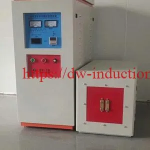
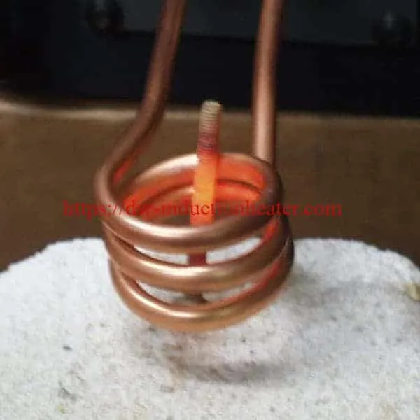
Induction annealing of bolt shafts heats a fastener shaft to a controlled temperature to relieve residual stress, restore ductility or soften a grade before a downstream operation — using a high-frequency coil instead of a flame or a furnace. HLQ’s reference application uses a DW-UHF-4.5 kW induction heating system running at 280 kHz, with a remote workhead containing one 0.66 µF capacitor driving a custom three-turn helical coil built for this job.
The published case data: 431 stainless steel bolts are heated to 1850 °F (1010 °C); Inconel and 8740 alloy steel bolts are heated to 1000 °F (538 °C). The same coil covers the range — 10–12 seconds for large bolts and 18–20 seconds for smaller bolts. Heating is hands-free and flameless, and the cycle is repeatable from bolt to bolt.
Table of Contents
- Quick Answer
- What is the Induction Annealing Machine for Bolt Shafts?
- Key Applications
- Suitable Materials
- Working Principle
- Technical Specifications
- Recommended Model Selection
- Process Workflow
- Common Problems and Solutions
- Engineering Selection Guide
- Advantages and Limitations
- Why Choose HLQ?
- 6 Core FAQs
What is the Induction Annealing Machine for Bolt Shafts?
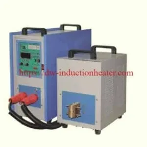
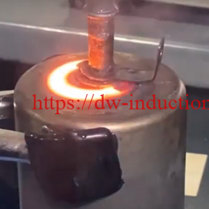
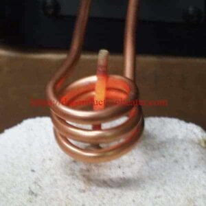
A bolt-shaft annealing station is an induction heating cell built around a solid-state power supply, a remote workhead and a purpose-designed helical coil. A bolt shaft is placed on the coil axis, alternating current at high frequency induces eddy currents inside the shaft, and the shaft heats from within to a set target temperature. The process is non-contact, flameless and locally controlled — heat is applied only where the coil sits, so the head, the threads and the surrounding air are not exposed to a flame.
Annealing here means bringing the shaft to a defined temperature to relieve residual stress and soften the micro-structure, not hardening it. That is the key distinction from an induction shaft hardening machine, which heats a surface rapidly and quenches it.
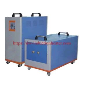
The reference HLQ installation uses the DW-UHF-4.5 kW class of induction heating power supply with a remote workhead containing one 0.66 µF capacitor, feeding a three-turn helical coil. The remote workhead is what makes the cell practical: the power electronics stay at the rear of the bench while the coil and the operator are at the front, so the operator works at the station instead of walking to the machine.
Because the same three-turn coil anneals both large and small bolts without a changeover, the station needs one coil design, one power supply and one parameter set.
Key Applications
- Stress relief before machining — releasing locked-in stress in cold-formed or forged fastener shafts so they machine cleanly and stay dimensionally stable.
- Softening before cold forming or thread rolling — lowering hardness so the material deforms rather than cracks.
- Post-weld stress relief — annealing the heat-affected zone of a welded fastener assembly without discolouring the parent metal.
- Micro-structure conditioning of stainless grades — putting 431 martensitic stainless into a defined tempered condition before use.
- Nickel-alloy and high-strength alloy stress relief — annealing Inconel-family and 8740 alloy steel fasteners to a specified condition.
- Pre-brazing or pre-joining preparation — bringing a stainless or alloy shaft to a uniform temperature so a following silver-solder or brazing step starts from an even baseline.
- Batch processing of mixed fastener sizes — one coil, one station, different parameter sets per grade and size.
For the wider family of thermal processes HLQ supports, see the induction annealing technology overview and the basics of induction heating page.
Suitable Materials
The published case covers three fastener grades, at two distinct temperature targets. All three are electrically conductive ferrous or nickel alloys, which is what makes induction heating efficient for them.
| Material | Annealing temperature | Temperature | Cycle time (as run) |
|---|---|---|---|
| 431 stainless steel bolts | 1850 °F | 1010 °C | 10–12 s (large bolts) / 18–20 s (smaller bolts) |
| Inconel bolts | 1000 °F | 538 °C | 10–12 s (large bolts) / 18–20 s (smaller bolts) |
| 8740 alloy steel bolts | 1000 °F | 538 °C | 10–12 s (large bolts) / 18–20 s (smaller bolts) |
Engineering note on the 431 stainless target. The 1850 °F (1010 °C) figure is the as-run value in the published case. It sits at the upper end of the annealing range commonly quoted for 431 martensitic stainless steel, and it is close to the point where surface oxidation and grain coarsening become a concern. Confirm the target against your own material specification, hardness requirement and section size before locking a cycle. The 1000 °F (538 °C) target used for the Inconel and 8740 bolts is a stress-relief soak.
Because these are fast, repeatable heat cycles on conductive alloys, the process suits grades with predictable, well-documented thermal response. If your grade is not listed here, the method is usually still applicable — what changes is the target temperature, the power needed and the coil design.
Working Principle

High-frequency alternating current flows from the DW-UHF-4.5 kW power supply into the remote workhead, where a single 0.66 µF capacitor forms the resonant tank circuit. The workhead feeds a three-turn helical coil placed around the bolt shaft.
The coil’s alternating field links the steel or nickel-alloy shaft and induces circulating eddy currents in the shaft itself. Resistance in the current path converts that energy into heat, concentrated in the region encircled by the coil. Because the heat is generated inside the workpiece rather than transferred to it from outside, the shaft heats rapidly and the surface heats last — the opposite of a torch.
The coil turns are spaced so that the induced current density produces a heat band of the required length along the shaft. The frequency sets how deep the current penetrates: at 280 kHz the skin depth in steel is shallow, so heat is concentrated near the surface, which is what makes a short, well-defined heated zone rather than the whole shaft glowing.
When the target temperature is reached, the power is cut and the shaft cools. Because the process is entirely electrical and the coil does not move, the result is repeatable: the same bolt, in the same position in the same coil, receives the same thermal history.
For the fundamentals of how the field and current interact, read the basics of induction heating work.
Technical Specifications
Reference application data — DW-UHF-4.5 kW bolt shaft annealing
| Parameter | Value |
|---|---|
| Power supply | DW-UHF-4.5 kW induction heating system |
| Workhead | Remote workhead with one 0.66 µF capacitor |
| Induction coil | Custom-designed three-turn helical coil |
| Operating frequency | 280 kHz |
| Workpieces | Bolt shafts, various sizes |
| Materials | 431 stainless steel, Inconel, 8740 alloy steel |
| Target temperature — 431 stainless | 1850 °F (1010 °C) |
| Target temperature — Inconel and 8740 | 1000 °F (538 °C) |
| Cycle time — large bolts | 10–12 s |
| Cycle time — smaller bolts | 18–20 s |
| Coil changeover between sizes | None — the same coil is used |
DW-UHF series — published model specifications
| Model | Rated power | Input current | Oscillation frequency | Input supply | Duty cycle |
|---|---|---|---|---|---|
| DW-UHF-3.2KW | 3.2 kW | 13 A | 1.1–2.0 MHz | Single-phase 220 V ±10% | 100% |
| DW-UHF-4.5KW | 4.5 kW | 20 A | 1.1–2.0 MHz | Single-phase 220 V ±10% | 100% |
| DW-UHF-045T | 4.5 kW | 20 A | 1.1–2.0 MHz | Single-phase 220 V ±10% | 100% |
| DW-UHF-045L | 4.5 kW | 20 A | 1.1–2.0 MHz | Single-phase 220 V ±10% | 100% |
| DW-UHF-6.0KW | 6.0 kW | 28 A | 1.1–2.0 MHz | Single-phase 220 V ±10% | 100% |
| DW-UHF-06A | 6.0 kW | 28 A | 1.1–2.0 MHz | Single-phase 220 V ±10% | 100% |
| DW-UHF-6KW-B | 6.0 kW | 28 A | 1.1–2.0 MHz | Single-phase 220 V ±10% | 100% |
| DW-UHF-10KW | 10 kW | 15 A | 100–500 kHz | 3 × 380 V ±10% | 100% |
| DW-UHF-20KW | 20 kW | 30 A | 50–250 kHz | 3 × 380 V ±10% | 100% |
| DW-UHF-30KW | 30 kW | 45 A | 50–200 kHz | 3 × 380 V ±10% | 100% |
| DW-UHF-40KW | 40 kW | 60 A | 50–200 kHz | 3 × 380 V ±10% | 100% |
| DW-UHF-60KW | 60 kW | 90 A | 50–150 kHz | 3 × 380 V ±10% | 100% |
Configuration note. The bolt-shaft annealing reference cell runs at 280 kHz through a remote workhead with one 0.66 µF capacitor, which is a different configuration from the portable 1.1–2.0 MHz DW-UHF-4.5KW unit published above. Confirm with your supplier which source and workhead combination is supplied with the remote-workhead build before ordering.
DW-UHF-4.5KW portable unit — published physical and electrical data
| Item | Published value |
|---|---|
| Output power | 4.5 kW |
| Input supply | Single-phase 220 V (tolerance to be confirmed) |
| Utility frequency | 50/60 Hz |
| Oscillation frequency | 1100–2000 kHz |
| Input current | 5–20 A (listed inconsistently across the site — confirm) |
| Weight | 21 kg |
| Main unit dimensions | 330 × 310 × 155 mm |
| Workhead dimensions | 125 × 60 × 95 mm |
| Inverter technology | IGBT, current-inverter type |
| Control modes | Constant-current or constant-power selectable |
| Duty cycle | 100% |
| Quench capability | Quench thickness below 1 mm |
| Display | Heating power and current |
Recommended Model Selection
Model choice for bolt-shaft annealing is driven by three things: the mass of material that has to be heated per cycle, the length of the heated zone, and the target temperature. Frequency follows from how the heat should be distributed; power follows from how much energy must be delivered in the available cycle time.
| Application profile | Source class | Frequency band | Supply | Coil configuration |
|---|---|---|---|---|
| Small and medium fastener shafts, mixed grades, bench or single-station work | DW-UHF-4.5KW / 045T / 045L class | 280 kHz solid-state build with remote workhead | Single-phase 220 V | Three-turn helical coil, remote workhead with one 0.66 µF capacitor |
| Micro-soldering, fine connectors, small precision parts | DW-UHF-3.2KW / 6.0KW / 06A / 6KW-B class | 1.1–2.0 MHz | Single-phase 220 V | Application-specific coil or portable induction unit |
| Larger shafts, continuous or semi-continuous duty | DW-UHF-10KW to 60KW class | 50–500 kHz depending on model | 3 × 380 V | Application-specific helical coil |
| Automated shafts, pins, rods and gears needing surface hardening | DW-MF series, medium frequency | Low kHz class | 3 × 380 V | Configured for shaft hardening rather than annealing |
Selection rule of thumb. If a single bolt can be annealed to temperature within the 10–20 second window typical of the reference case, the DW-UHF-4.5 kW class with a remote workhead is the starting point. Step up the power class when the heated zone grows beyond a single coil length or when the cell must run two shifts without stopping — all models in the table are rated for 100% duty cycle. See the IGBT induction heating machine page for the full induction heating system configurations.
Process Workflow

- Load the bolt. Insert the shaft into the three-turn helical coil so the intended heated band sits inside the coil turns.
- Set the position. Confirm the heating length, the axial position of the coil on the shaft, and the coil-to-shaft stand-off. Position is the single biggest determinant of repeatability.
- Connect the workhead. Plug the remote workhead with its 0.66 µF capacitor into the supply and seat the coil lead in the workhead.
- Load the profile. Enter power, frequency and target temperature for the grade and size: 1850 °F (1010 °C) for 431 stainless, 1000 °F (538 °C) for Inconel and 8740.
- Energise. Switch on the 280 kHz source. Heating is hands-free once started.
- Heat to target. The eddy-current heating zone brings the shaft to the set temperature in 10–12 seconds for large bolts and 18–20 seconds for smaller bolts.
- Hold and soak. Soak at target to equalise the cross-section so the result is not surface-only.
- Power down. De-energise and let the bolt cool naturally. Do not quench unless a specific hardness result calls for it.
- Inspect. Check hardness and micro-structure once the bolt has cooled.
- Repeat. Feed the next bolt. The cycle time is repeatable because the coil, the position and the parameters are fixed.

Putting the power supply at the rear of the cell and the remote workhead at the operator position keeps the leads off the operator side, keeps the mains inlet away from the hot work area, and puts the coil within a short reach of the operator. There is no open flame at the station. For comparison with torch-based heating, see induction heating vs flame heating.
Common Problems and Solutions
| Symptom | Likely cause | Action |
|---|---|---|
| Shaft does not reach target temperature within the expected cycle time | Coil-to-shaft stand-off too large, or the bolt is positioned off the coil axis | Re-seat the shaft on the coil axis and close the stand-off to the design value. Heated length and coupling efficiency set the energy actually delivered to the workpiece |
| Heated band runs hot at one end and cold at the other | Coil not square to the shaft, or the shaft not axially centred in the turns | Re-align the coil perpendicular to the shaft axis and re-position the bolt before re-running. Turn spacing defines the length of the heat band |
| Temperature overshoots the target on smaller bolts | Cycle time too long for the reduced thermal mass | Shorten the energised time. The published data already shows smaller bolts needing 18–20 s against 10–12 s for large ones, and the reverse error is easy to make |
| Uneven heating around the circumference of the shaft | Shaft not centred in the coil bore, or a deformed coil turn | Re-centre the workpiece and inspect the coil for out-of-round turns. The three-turn helical geometry is sensitive to stand-off |
| Visible surface oxidation or scale after annealing | Time at temperature too long, or air exposure too long at high target | Trim the soak, review the 1850 °F target against your material specification, and transfer hot bolts out of the air quickly |
| Cooling starts before the process ends | Operator removes the bolt on time rather than on temperature | Hold the bolt in the coil until the target is reached and the soak is complete. The cell is hands-free by design |
| Coil or workhead runs hot | Duty beyond the design coil loading, or a workhead capacitor mismatch | Check the workhead capacitor value against the design — the reference build uses a single 0.66 µF capacitor — and confirm the coil is not being over-coupled to a large workpiece |
| Cycle-to-cycle results vary | Coil position, parameter set or part orientation not standardised | Fix the coil in a repeatable position, lock the parameter set per grade and size, and re-verify against the 10–12 s / 18–20 s windows |
| Supply trips or behaves erratically | Mains supply or input current outside the published envelope | Confirm single-phase 220 V supply, 50/60 Hz utility frequency and the rated input current. The site publishes an inconsistent input-current range for the 4.5 kW unit — verify the actual value before sizing the breaker |
Engineering Selection Guide
Work through these five questions in order when specifying a bolt-shaft annealing cell.
- What is the target condition? Stress relief, softening before forming, or micro-structure conditioning. This sets the temperature and, for stainless grades, the soak time.
- What is the grade? 431 stainless, Inconel and 8740 all anneal in this cell but at different targets — 1010 °C versus 538 °C. Grade and temperature are not independent variables.
- How much material must be heated per cycle? This is the driver of power. Small shafts on a single coil length are the DW-UHF-4.5 kW class; longer heated zones or heavier sections move you up the DW-UHF range.
- How long a heated zone is needed? A single three-turn helical coil covers one band. Multiple bands need multiple passes or a multi-zone coil — plan the coil design around this before anything else.
- What is the production rate? If parts-per-hour matters more than station simplicity, a dedicated automated line is more appropriate than a bench cell. HLQ’s automated shaft, pin and rod configurations are covered separately.
Specification checklist before release. Bolt diameter and shaft length range; grade and required hardness or tensile target; heated zone length; parts per hour; available supply (single-phase 220 V or three-phase 380 V); required coil stand-off; whether the cell runs attended or unattended; and the inspection method you will use to confirm the result. An induction heating cell for precision work follows the same planning logic with tighter tolerance on the temperature hold.
Advantages and Limitations
Advantages
- Fast. 10–12 seconds for large bolts and 18–20 seconds for smaller ones against the minutes that a flame or batch furnace needs.
- Local. Heat is generated only in the coil zone, so threads, head and surrounding parts are not thermally soaked.
- Repeatable. Fixed coil, fixed position, fixed parameters give the same thermal history on every bolt, which is what makes the process auditable.
- Flameless and hands-free. No open flame at the station and no operator skill is needed once the cycle is running.
- One coil covers the size range. No coil changeover between large and small bolts, which removes setup time and a source of error.
- Clean and contained. No combustion products and no ambient heat load in the work area.
- 100% duty cycle across the published DW-UHF range.
Limitations
- Coil design is application-specific. The three-turn helical coil in this case was custom-designed for the bolt range in question. A new diameter range means a new coil, and the coil is a consumable item over time.
- Heat is concentrated, not uniform through the section. Very heavy sections need a soak to equalise the core, which extends cycle time.
- Not every geometry is well suited. Deep re-entrant features, internal bores and very short shafts couple poorly to a coil and may need a different tool.
- Power supply class sets the ceiling. The 4.5 kW class covers this application; materially larger sections need the 10 kW and above models with three-phase supply.
- Hot-part handling still needs a plan. The process is flameless, not cool — parts leave the coil at temperature and need somewhere to cool safely.
- Target temperatures are case data, not a specification. The published figures come from one application; confirm them against your own material specification and acceptance criteria.
Why Choose HLQ?
HLQ (DW Induction Heating, Dongguan, Guangdong) builds and supports a full frequency ladder rather than a single machine class: DW-UHF for ultra-high-frequency work from 3.2 kW to 60 kW, DW-HF and DW-MF for medium- and low-frequency heavy work, and a full solid-state line for continuous production.
- IGBT solid-state inverters with selectable constant-current or constant-power control, running at 100% duty cycle across the published range.
- Remote workhead architecture, which is what makes the bolt-shaft cell practical: the operator works at the front of the bench while the electronics stay at the rear.
- An application library rather than catalogue pages. Published case data across annealing, brazing, hardening, preheating, powder coating and paint stripping lets you see real parameters before you commit.
- Application-specific coil engineering, as in the three-turn helical coil developed for the 431 stainless, Inconel and 8740 bolt case.
- Cost and energy efficiency relative to flame or batch-furnace annealing, since only the workpiece is heated.
- A multilingual technical site and direct engineering contact, so coil and parameter questions reach the people who built the machine.
For the wider equipment range, start from the induction heating power supply range and the energy-efficient induction heating overview.
6 Core FAQs
1. What temperature do you anneal bolt shafts to?
In the published HLQ application, 431 stainless steel bolts are annealed at 1850 °F (1010 °C), and Inconel and 8740 alloy steel bolts at 1000 °F (538 °C). These are as-run case figures. The 1850 °F figure sits at the upper end of the range commonly quoted for 431 martensitic stainless, so confirm the target against your own material specification and acceptance criteria before locking in a cycle.
2. How long does it take to anneal a bolt shaft?
Between 10 and 12 seconds for large bolts and 18 and 20 seconds for smaller bolts, using the same three-turn helical coil for both. The shorter time applies to the larger thermal mass, because the power and coil loading are already at their ceiling and only the mass to be heated changes.
3. Which induction heating machine is used for bolt shaft annealing?
A DW-UHF-4.5 kW induction heating system operating at 280 kHz, with a remote workhead containing one 0.66 µF capacitor and a custom-designed three-turn helical coil. For larger shafts or heavier heated zones, step up through the DW-UHF 10 kW to 60 kW models, which run on three-phase 380 V and cover 50–500 kHz depending on the model.
4. Do you need a different coil for different bolt sizes?
Not in this application. The same three-turn helical coil annealed both large and smaller bolts in the published case, which means one coil design, one power supply and one parameter set across the size range. A materially different diameter range, a different heated-zone length or a different grade at a very different target would justify a re-designed coil.
5. How does induction annealing differ from flame or furnace annealing?
Heat is generated inside the workpiece by induced eddy currents rather than transferred to it from a flame or a hot atmosphere. The consequences are that only the coil zone is heated, cycle times are measured in seconds rather than minutes, the process is flameless and hands-free, and every bolt receives the same thermal history. Against flame heating in particular, the case for induction is one of control, safety and cycle time — see the induction versus flame heating comparison for the general case.
6. Is induction annealing suitable for stainless steel and nickel alloys?
Yes. Both 431 stainless steel and Inconel are electrically conductive and respond efficiently to induction heating, and both are covered in the published application alongside 8740 alloy steel. The practical difference between them is the target temperature — 1010 °C for the 431 stainless against 538 °C for the Inconel and 8740 — not the heating method. Non-conductive materials, and coated or plated surfaces that would be damaged at temperature, need a different approach.