Annealing Brass Tubing With Induction
Annealing Brass Tubing With Induction for Mandrel Bending
Quick Answer
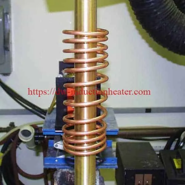
Induction annealing of brass tubing heats only the length of tube that a mandrel bender is going to work, so the metal is ductile where the bend is formed and the rest of the tube keeps its temper. HLQ’s reference application anneals brass and bronze tubing for bending in a mandrel bender to form handrails, using a DW-UHF-6 kW induction heating system at 300 kHz with a remote workhead containing two 0.5 µF capacitors and a custom-designed twelve-turn helical coil.
The published case data: the coil heats an 8 in (20.3 cm) length of tube, positioned 3 in (7.6 cm) along the tube axis from the bend line, to a target of 1000 °F (538 °C). It covers brass tubes 1.5 in (38.1 mm) and 2 in (50.8 mm) diameter at 0.065 in (1.65 mm) wall, and bronze tubes at the same diameters with a 0.100 in (2.54 mm) wall. The stated benefits are high efficiency and low energy consumption, precise and controllable heat placement, hands-free heating requiring no specialist operator skill, and uniform heat distribution that removes cracking during bending.
Two engineering points this page exists to make clear. First, the heat zone is referenced to the bend, not to the tube end — the 3 inch offset is a distance measured along the tube axis, which is what lets a single fixed coil serve every bend position on the tube. Second, 1000 °F is the right target but only if the bend is made cold: published data puts the annealing range for 70/30 cartridge brass at 800–1400 °F and for naval brass at 800–1200 °F, while higher-zinc brasses become hot short above roughly 600–700 °F. The tube is annealed hot and then bent cold over the mandrel after it has cooled.
Table of Contents
- Quick Answer
- What is the Induction Annealing Machine for Brass Tubing?
- Key Applications
- Suitable Materials
- Working Principle
- Technical Specifications
- Recommended Model Selection
- Process Workflow
- Common Problems and Solutions
- Engineering Selection Guide
- Advantages and Limitations
- Why Choose HLQ?
- 6 Core FAQs
What is the Induction Annealing Machine for Brass Tubing?
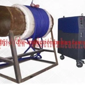
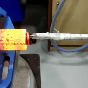
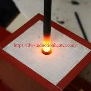
A brass tubing annealing station is an induction heating cell built around a solid-state power supply, a remote workhead and a helical coil that the tube passes through. High-frequency alternating current induces eddy currents in the tube wall, and the tube heats from within to a controlled temperature along the length of the coil. The process is non-contact, flameless and precisely localised in length.
Annealing here means restoring ductility in tube that has been work-hardened by drawing or forming, so that it can be bent without tearing or cracking. That is the entire purpose: not a hardening operation, and not a general heat treatment, but one specific preparation step for one specific downstream operation.
The defining feature of this configuration is where the heat zone sits relative to the bend. The coil is a fixed twelve-turn helical design, and the tube is positioned so that the heated length ends 3 inches short of the bend line. The bend is therefore made in material that has just been annealed, while the tube either side of it keeps its original temper. Because the coil never moves, the cell needs no re-fixturing between bends — the operator positions the tube against a stop, and the geometry does the rest.
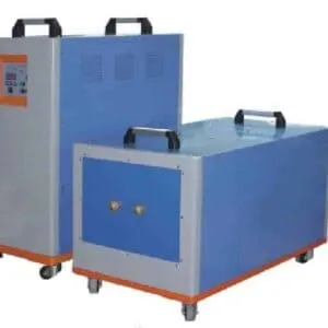
The reference HLQ installation uses the DW-UHF-6 kW class of induction heating power supply with a remote workhead containing two 0.5 µF capacitors and a custom twelve-turn helical coil. The remote workhead is what makes the cell practical: the power electronics stay at the rear of the bench while the coil and the operator are at the front.
The same platform handles adjacent brass and copper work: induction brazing of brass fittings at 750 °C, induction annealing of copper tube at 1500 °F, and induction annealing of a brass electrical contact in 1.5 seconds. For the underlying physics, read the basics of induction heating work.
Key Applications
- Annealing brass tubing for handrail bending — the published HLQ application. Annealing the bend zone so the tube forms cleanly over a mandrel without splitting, and without work-hardening the dies.
- Annealing bronze tubing for bending — the same process on bronze, where the heavier 0.100 in wall needs more energy and a longer cycle than the 0.065 in brass wall.
- Preparing tube for a mandrel bender or rotary draw bender — restoring ductility in drawn tube so the bend radius can be held without ovalising or flattening the wall.
- Stress relief before fabrication — relieving residual stress in cold-worked tube so it stays dimensionally stable through the bend and after assembly.
- Annealing before brazing or soldering a tube assembly — softening the tube for a following joint operation. Note this is a different process from the brazing itself, which HLQ covers separately.
- Annealing brass or copper wire and strip for forming — the same physics applied to a different workpiece, with the wire running through a multi-turn coil. HLQ’s wire case reaches 572 °F in 5 seconds.
- Annealing the working end of a stamp or punch — so the end mushrooms under the hammer instead of cracking.
- Annealing the end of a metal stamp set — a related S-7 steel application at 1400–1800 °F using one five-turn and two four-turn coils.


Suitable Materials
Published case — brass and bronze tubing for handrail bending
| Parameter | Value |
|---|---|
| Objective | Anneal brass and bronze tubing for bending in a mandrel bender to form handrails |
| Materials | Brass tubes 1.5 in (38.1 mm) and 2 in (50.8 mm) diameter, 0.065 in (1.65 mm) wall; bronze tubes 1.5 in and 2 in diameter, 0.100 in (2.54 mm) wall |
| Target temperature | 1000 °F (538 °C) |
| Frequency | 300 kHz |
| Equipment | DW-UHF-6 kW induction heating system |
| Workhead | Remote workhead containing two 0.5 µF capacitors |
| Coil | Custom-designed twelve-turn helical coil |
| Heated length | 8 in (20.3 cm) |
| Zone position | 3 in (7.6 cm) along the tube axis from the bend line |
| Per-size detail | Each of the four tube sizes runs its own heating cycle and time |
| Stated benefits | High efficiency, low energy consumption; precise and controllable heat placement; hands-free heating, no operator skill required; uniform heat distribution that removes cracking during bending |
Brass and bronze — published data
| Property | C26000 cartridge brass (70/30) | C46400 naval brass |
|---|---|---|
| Composition | Cu 68.5–71.5 %, Zn balance, Pb max 0.07 %, Fe max 0.05 % | Cu ~60–63 %, Zn balance, ~1 % Sn for dezincification resistance |
| Structure | Single-phase alpha brass | Alpha-beta, higher Zn |
| Melting range | Solidus ~916 °C (1680 °F), liquidus ~955 °C (1750 °F) | Lower than C26000 as Zn rises |
| Published annealing range | 800–1400 °F | 425–650 °C (800–1200 °F) |
| Published stress-relief range | Low-temperature stress relief to prevent season cracking | 250–300 °C (475–570 °F) |
| Hot working range | 750–830 °C | Not applicable — cold worked |
| Hot shortness | Becomes hot short above roughly 600–700 °F, as do the other higher-Zn brasses | Same — higher-Zn alloys are cold worked rather than hot formed |
| Electrical conductivity | ≈28 %IACS | ≈25 %IACS (per ASTM B193 for zinc alloy conductivity) — low-zinc C230 retains good hot formability |
| Resistivity | 37.0 Ω·cmil/ft (6.15 µΩ·cm) | Higher than C26000 as Zn rises |
| Density | 8.53 g/cm³ | 8.53 g/cm³ approximately |
| Thermal conductivity | 121 W/m·K | Lower than C26000 |
| Elastic modulus | 110 GPa | Approximately 105 GPa |
| Temper condition | Not heat treatable — strength comes entirely from cold work (H02, H04 etc.) | Supplied in 1/4 hard, 1/2 hard, hard or soft-annealed (O60); 1/4 hard ≈67–70 ksi with 25–35 % elongation, soft annealed ≈56–58 ksi with 45–47 % elongation |
| Forms | ASTM B36 tube; ISO CuZn30, BSI CZ106, JIS C 2600, EN CW505L | ASTM B21 rod, ASTM B124, ASTM B171 tube |
Why 1000 °F is the right target — and the condition that goes with it
- The target sits inside the published annealing range for both families: 800–1400 °F for C26000 and 800–1200 °F for C46400. At 1000 °F the cold-worked structure recrystallises and the tube returns to a ductile condition.
- The target is below the hot-shortness threshold for higher-zinc brasses, which become hot short above roughly 600–700 °F. That threshold is why brass is cold worked rather than hot formed — and why the bend is made cold.
- The practical instruction that follows: the tube is annealed hot, then cooled and bent cold over the mandrel. Bent hot, the tube will split. This single distinction is the most common failure in handrail production and the original page never states it.
- Zinc is not the concern at this temperature. Zinc volatilisation in brass becomes significant well above 538 °C; the concern at this target is the bending behaviour, not alloy loss.
Skin depth against the tube wall — calculated
Skin depth δ = √(ρ / (π·f·µ·µ₀)), using the published C26000 resistivity of 6.15 µΩ·cm and relative permeability ≈ 1 (brass is non-magnetic).
| Tube | Wall thickness | Skin depth at 300 kHz | Skin depth as % of wall |
|---|---|---|---|
| 1.5 in brass | 0.065 in (1.65 mm) | ≈0.23 mm | 14 % |
| 2 in brass | 0.065 in (1.65 mm) | ≈0.23 mm | 14 % |
| 1.5 in bronze | 0.100 in (2.54 mm) | ≈0.23 mm | 9 % |
| 2 in bronze | 0.100 in (2.54 mm) | ≈0.23 mm | 9 % |
The current is concentrated in a thin layer of the outer wall, so the inner wall heats by conduction. For a tube this matters more than for a solid bar, because the mandrel bears on the inner surface — the last part to reach temperature. It is why a short cycle needs a soak and why the temperature should be verified on the part rather than inferred from the setpoint.
Working Principle
High-frequency alternating current flows from the DW-UHF-6 kW power supply into the remote workhead, where two 0.5 µF capacitors form the resonant tank circuit. The workhead feeds the twelve-turn helical coil, which encircles the tube.
The coil’s alternating magnetic field links the brass and induces circulating eddy currents in the tube wall. Resistance in the current path converts that energy into heat, generated inside the workpiece rather than transferred to it from outside. The tube therefore heats rapidly and from within — the opposite of a torch, where the outside surface is always hottest and the heat has to conduct inwards.
Frequency determines how deep the induced current penetrates. At 300 kHz in brass the skin depth is approximately 0.23 mm, so the current occupies a thin layer of the outer wall and the inner wall heats by conduction. For a tube that is the point worth understanding: the mandrel bears on the inner surface, which is the last part of the section to reach temperature.
Coil turn count is set by the impedance the coil must present to match the tube’s load. Twelve turns over an 8 in length is the published design point. Changing tube diameter changes the load, and the coil must be re-designed for it.
Axial position is the defining geometric decision in this application. The heated zone ends 3 inches short of the bend line, so the material that will be bent has just been annealed while the rest of the tube is untouched. Because the coil is fixed and the tube is positioned against a stop, one coil serves every bend position on the tube.
For the underlying physics, read the basics of induction heating work.
Technical Specifications
Reference application data — DW-UHF-6 kW brass and bronze tubing annealing
| Parameter | Value |
|---|---|
| Power supply | DW-UHF-6 kW induction heating system |
| Workhead | Remote workhead containing two 0.5 µF capacitors |
| Induction coil | Custom-designed twelve-turn helical coil |
| Operating frequency | 300 kHz |
| Target temperature | 1000 °F (538 °C) |
| Heated length | 8 in (20.3 cm) |
| Zone position relative to the bend | 3 in (7.6 cm) along the tube axis |
| Workpieces | Brass tubes 1.5 in and 2 in dia, 0.065 in wall; bronze tubes 1.5 in and 2 in dia, 0.100 in wall |
| Heating cycle per size | Each of the four tube sizes runs its own heating cycle and time |
| Downstream operation | Bending on a mandrel bender, to form handrails |
DW-UHF-6KW — published specifications
| Item | Published value |
|---|---|
| Model | DW-UHF-6KW |
| Cooling | Air-cooled |
| Output power | 6.6 kW |
| Input supply | Single-phase 220 V, 50–60 Hz |
| Input current | 5–30 A |
| Inverter technology | Third-generation IGBT |
| Control modes | Constant-current or constant-power selectable |
| Duty cycle | 100% |
| Quench capability | Quench depth controllable below 1 mm |
| Weight | 25 kg |
| Main unit dimensions | 520 × 240 × 500 mm |
| Handpiece dimensions | 140 × 90 × 90 mm |
| Stated applications | Quick quenching, shallow-depth hardening, brazing of small workpieces, heating small parts, diamond blade segment brazing, carbon steel / PCBN blade brazing, eyeglass frame brazing, jewellery and watchcase brazing, electronics brazing and welding, small bearing quenching and annealing, stainless steel strip annealing, copper-to-copper pipe brazing |
The three 6 kW UHF variants — select by frequency band
| Model | Power | Current | Oscillation frequency | Input supply | Duty cycle |
|---|---|---|---|---|---|
| DW-UHF-6.0KW-I | 6.0 kW | 28 A | 1.1–2.0 MHz | Single-phase 220 V | 100% |
| DW-UHF-6KW-II | 6.6 kW | 30 A | 200–700 kHz | Single-phase 220 V | 100% |
| DW-UHF-6KW-III | 6.6 kW | 30 A | 500–1100 kHz | Single-phase 220 V | 100% |
This application runs at 300 kHz, which is inside the DW-UHF-6KW-II band of 200–700 kHz. The -III variant is specified at 500–1100 kHz. Confirm which unit is supplied and state the designation consistently across the application notes — the site currently mixes “DW-UHF-6.0KW-II” and “DW-UHF-6KW-II” spellings, and only the second appears in the published table.
DW-UHF series — published model specifications
| Model | Rated power | Input current | Oscillation frequency | Input supply | Duty cycle |
|---|---|---|---|---|---|
| DW-UHF-3.2KW | 3.2 kW | 13 A | 1.1–2.0 MHz | Single-phase 220 V ±10% | 100% |
| DW-UHF-4.5KW | 4.5 kW | 20 A | 1.1–2.0 MHz | Single-phase 220 V ±10% | 100% |
| DW-UHF-045T | 4.5 kW | 20 A | 1.1–2.0 MHz | Single-phase 220 V ±10% | 100% |
| DW-UHF-045L | 4.5 kW | 20 A | 1.1–2.0 MHz | Single-phase 220 V ±10% | 100% |
| DW-UHF-6.0KW | 6.0 kW | 28 A | 1.1–2.0 MHz | Single-phase 220 V ±10% | 100% |
| DW-UHF-06A | 6.0 kW | 28 A | 1.1–2.0 MHz | Single-phase 220 V ±10% | 100% |
| DW-UHF-6KW-B | 6.0 kW | 28 A | 1.1–2.0 MHz | Single-phase 220 V ±10% | 100% |
| DW-UHF-10KW | 10 kW | 15 A | 100–500 kHz | 3 × 380 V ±10% | 100% |
| DW-UHF-20KW | 20 kW | 30 A | 50–250 kHz | 3 × 380 V ±10% | 100% |
| DW-UHF-30KW | 30 kW | 45 A | 50–200 kHz | 3 × 380 V ±10% | 100% |
| DW-UHF-40KW | 40 kW | 60 A | 50–200 kHz | 3 × 380 V ±10% | 100% |
| DW-UHF-60KW | 60 kW | 90 A | 50–150 kHz | 3 × 380 V ±10% | 100% |
| DW-UHF-100KW | 100 kW | 145 A | 50–150 kHz | 3 × 380 V | 100% |
DW-HF series — published model specifications
| Model | Max input power | Max input current | Frequency | Input voltage | Duty cycle |
|---|---|---|---|---|---|
| DW-HF-04 (4KW-A) | 4 kVA | 15 A | 100–250 kHz | Single-phase 220 V | 80% |
| DW-HF-15KW-A / -B | 15 kVA | 32 A | 30–100 kHz | Single-phase 220 V | 80% |
| DW-HF-25KW-A / -B | 25 kVA | 23 A | 20–80 kHz | 3-phase 380 V ±10% | 100% |
| DW-HF-35KW-B | 35 kVA | 51 A | 20–80 kHz | 3-phase 380 V | 100% |
| DW-HF-45KW-B | 45 kVA | 68 A | 20–80 kHz | 3-phase 380 V | 100% |
| DW-HF-60KW-B | 60 kVA | 105 A | 20–80 kHz | 3-phase 380 V | 100% |
| DW-HF-80KW-B | 80 kVA | 130 A | — | 3-phase 380 V | 100% |
| DW-HF-90KW-B | 90 kVA | 160 A | — | 3-phase 380 V | 100% |
| DW-HF-120KW-B | 120 kVA | 200 A | — | 3-phase 380 V | 100% |
All DW-HF units use IGBT inverter technology; the 25 kW and larger models support three-phase supply for continuous (100%) duty cycle. The 15 kW frequency band is listed as 30–100 kHz on some English pages and 30–80 kHz on others — confirm before ordering.
Recommended Model Selection
Model choice for brass tubing annealing is driven by four things: the mass of tube in the heated zone, the diameter and wall thickness, the target temperature, and the throughput. Frequency follows from how the heat should distribute through the wall; power follows from how much energy must be delivered in the available cycle time.
| Application profile | Source class | Frequency band | Supply | Published reference |
|---|---|---|---|---|
| Brass and bronze tube annealed ahead of a mandrel bender | DW-UHF-6KW-II | 200–700 kHz (300 kHz in this case) | Single-phase 220 V | This application — 12-turn helical coil, 8 in heated length, 3 in offset from the bend line, 1000 °F (538 °C), remote workhead with two 0.5 µF capacitors |
| Wire annealed ahead of a forming operation | DW-UHF-6KW-II | 200–700 kHz (300 kHz) | Single-phase 220 V | Zinc wire 0.18 in / 4.5 mm to 572 °F (300 °C) in 5 s, 14-turn coil, 100 mm heated length |
| Brass fasteners, contacts and small stampings | DW-UHF-6KW-III / DW-UHF-10kW class | 310–500 kHz | Single-phase 220 V / 3 × 380 V | Brass spade contact to 1000 °F (538 °C) in 1.5 s with a one-turn hairpin coil |
| Copper tube annealed for forming or brazing | DW-HF-45kW class | 30–80 kHz | 3 × 380 V | 1.625 in × 24 in copper tube to 1500 °F (815.5 °C) with a four-turn helical coil, 7.5 s total, zone 1.5 in from each end, eight 1.0 µF capacitors |
| Continuous brass or copper wire annealing | DW-UHF-60kW class | 50–150 kHz | 3 × 380 V | Square copper wire 0.06 in at 842 °F (450 °C), 15 m/min, twelve-turn helical coil with a ceramic tube |
| Heavy sections and large assemblies | DW-HF-25KW to DW-HF-120KW class | 20–100 kHz | 3 × 380 V | Deep penetration for thick sections, with water cooling and remote extensions |
Selection rule of thumb. If one tube can be annealed in a short cycle and the wall is light, the DW-UHF-6KW-II class with a remote workhead is the starting point. Step up to the DW-UHF-10 kW class on three-phase supply when the diameter, the wall thickness or the heated length rises — as it does for the 0.100 in bronze wall — and to the DW-HF class for copper tube, where the higher conductivity of the material changes the power and coil requirements completely. See the IGBT induction heating machine page for the full induction heating system configurations.
Process Workflow
- Verify the tube. Confirm alloy, diameter and wall thickness. The published case covers four combinations — 1.5 in and 2 in brass at 0.065 in wall, and 1.5 in and 2 in bronze at 0.100 in wall.
- Set the target. 1000 °F (538 °C) for the published case. Set it against your own alloy’s published annealing range rather than adopting the number blindly.
- Fit the coil. The twelve-turn helical coil, custom designed for the tube diameter and the 8 in heated length.
- Mark the bend. Reference the bend line on the tube. The heat zone is positioned from this mark, not from the tube end.
- Position the zone. Set the heated length so it ends 3 inches short of the bend line. A stop on the tube support repeats this position for every tube.
- Energise. Switch on the source. Heating is hands-free once started.
- Heat to target. Run the heating cycle for that tube size. Each of the four sizes has its own cycle and time.
- Verify. Confirm the temperature with a pyrometer or temperature-indicating paint on the part, and check that the annealed band ends where it should.
- Cool. Let the tube cool before it goes to the bender. Brass is hot short — a bend made while the tube is still hot will split it.
- Bend. Straight to the mandrel bender, cold, over the mandrel.


Putting the source at the rear of the cell and the remote workhead at the operator position keeps the leads off the operator side and the mains inlet away from the hot work area. The bend-line stop on the tube support is the single most important piece of the cell: it repeats the 3 inch zone offset tube after tube, so the annealed band always lands in the same place relative to the bend. The layout logic is that the coil and the bender should be close together, because the tube must be cooled before it is bent and the fewer hands it passes the better. There is no open flame at the station. For the general case, see induction heating vs flame heating.
Common Problems and Solutions
| Symptom | Likely cause | Action |
|---|---|---|
| Tube cracks or splits during the bend | The bend was made while the tube was still hot, or the zone was not annealed | Cool the tube fully before bending — higher-zinc brass is hot short above roughly 600–700 °F. If it still cracks, the zone was not annealed or was not positioned on the bend |
| Tube ovalises or flattens at the bend | Wall is not supported, or the material is still hard | Use a correctly sized mandrel and a wiper die, and confirm the bend zone was annealed. A spring mandrel typically needs about 2 × OD minimum bend diameter, a rotary bender about 1.5 × |
| Annealed band is in the wrong place on the tube | Tube not seated against the bend-line stop | Re-seat the tube. The zone is defined by the stop, and the stop is the tolerance |
| Band position varies between tubes | Tubes vary in length, so a fixed stop gives a variable position | Set the stop by length for the batch, or use a length-indexed fixture |
| Wall is hot at the outside but cold at the inside | Skin depth is only about 0.23 mm in a 1.65–2.54 mm wall, so the inner wall heats by conduction | Lengthen the cycle or add a soak. The inner surface is the one the mandrel bears on, and it is the last to reach temperature |
| Tube reaches temperature too slowly | Power setpoint too low for the diameter and wall, or the coil is not matched to the tube | Check the coil design against the tube diameter. Brass at 28 %IACS couples far less strongly than copper, so a copper-derived coil design will underperform |
| Surface oxidation or discoloration after annealing | Time at temperature too long, or the tube sat in air too long before bending | Trim the hold and move the tube to the bender sooner. Scale on the tube surface shows up as die marking and as poor bend quality |
| Result varies between batches | Incoming tube condition changed, or the recipe was not updated | Verify the incoming temper with each lot. Each of the four published tube sizes runs its own cycle, so a change of size or wall needs a recipe change |
| Heating is weaker than expected after switching material | Conductivity changed — brass is roughly 28 %IACS against 100 %IACS for copper | Re-work the power setpoint and the coil for the new material. The same wattage that annealed the previous material will not anneal this one |
| Supply trips or behaves erratically | Mains supply or input current outside the published envelope | Confirm single-phase 220 V at 50/60 Hz and the rated 5–30 A input current before sizing the breaker or the circuit |
Engineering Selection Guide
Work through these five questions in order when specifying a brass tubing annealing cell.
- Which alloy, and what do you want from it? Ductility for bending, or stress relief alone? 1000 °F sits inside the published annealing range for both C26000 (800–1400 °F) and C46400 (800–1200 °F). If you only need stress relief, the published range for C46400 is much lower at 250–300 °C — a different and much cheaper job.
- Which diameters and wall thicknesses will you run? The published case covers four combinations. The bronze’s 0.100 in wall carries roughly 70 % more metal per unit length than the brass’s 0.065 in wall at the same diameter, so it needs a longer cycle and more power even though the diameter is the same.
- How long is the heated zone, and where is the bend? The 8 in heated length and the 3 in offset from the bend line together define the coil design and the fixture. Decide both before the coil is specified.
- How will you verify and how will you cool? The temperature should be verified on the part — pyrometer or temperature-indicating paint — and the tube cooled before bending. Both are part of the process, not optional extras, and both need a place in the cell layout.
- What is the throughput, and is the bend downstream? If the cell is part of a handrail line, the anneal and the bend should be close together so the tube is not handled hot and does not sit between the two. If the tube has to travel, the anneal should be the last step before it goes to the bender.
Specification checklist before release. Alloy grade and published anneal range; tube diameter, wall thickness and length range; required bend radius and the minimum bend diameter for the wall; target temperature and soak time; heated zone length and its offset from the bend line; parts per hour and bend cycle; available supply (single-phase 220 V or three-phase 380 V); coil design and bend-line stop concept; cooling method; the verification method you will accept; and the bend-line stop repeatability tolerance.
Advantages and Limitations
Advantages
- Heat only where the bend is. The 8 in heated zone ends 3 in short of the bend line, so the tube is softened where the mandrel works it and the rest of the length keeps its temper. Nothing else on the tube is thermally affected.
- A fixed coil serves every bend position. The tube is positioned against a stop rather than the coil being moved, so there is no re-fixturing between bends and no chance of the zone drifting.
- No flame, no furnace, no combustion products. The cell is flameless and the work area stays clear, which matters for a cell that sits next to a bender.
- Hands-free and repeatable. Once the recipe is set, the cycle needs no operator skill and gives the same thermal history on every tube.
- Uniform heat distribution. The published benefit that removes cracking during bending — the whole point of the process.
- High efficiency, low energy. Only the metal in the zone is heated, not the air and not the whole tube.
- Compact. 25 kg, 520 × 240 × 500 mm, single-phase 220 V — a bench-capable cell that can sit next to the bender.
- 100% duty cycle across the published DW-UHF range.
Limitations
- The bend must be made cold. This is the single most important limitation and it is not a limitation of the machine but of the material: higher-zinc brasses become hot short above roughly 600–700 °F. The tube is annealed hot and bent cold, and a bend made while the tube is still hot will split it.
- The coil is application-specific. Twelve turns over 8 in is a design for this diameter range and this wall thickness. A different diameter, wall or heated length means a new coil, and the coil is a wear item over time.
- The zone position is mechanical, not electronic. Correctness depends on the tube being seated against the bend-line stop every time. That is cheap and simple, but it is a mechanical tolerance that has to be maintained.
- Each tube size needs its own cycle. The published case runs four sizes, and each has its own heating time. A mixed production run means multiple recipes on the same cell.
- Heat is concentrated in the outer wall. At 300 kHz the skin depth in brass is about 0.23 mm, so the inner wall — the one the mandrel bears on — heats by conduction and lags the outside.
- The annnealed band is local. Only the length under the coil softens. If a bend needs a long radius that extends beyond the 8 in zone, the zone has to be lengthened, and the coil with it.
- Surface scale. Brass oxidises in the heated zone and the scale has to be cleaned or it marks the die and the finished surface.
- Target temperatures are case data, not a specification. The published figure comes from one application and two alloy families. Confirm against your own material specification and acceptance criteria.
Why Choose HLQ?
HLQ (DW Induction Heating, Dongguan, Guangdong) builds and supports a full frequency ladder rather than a single machine class: DW-UHF for ultra-high-frequency work from 3.2 kW to 100 kW, DW-HF for high-frequency industrial work with water cooling and remote extensions, and DW-MF for medium- and low-frequency heavy work including continuous forging lines.
- IGBT solid-state inverters with selectable constant-current or constant-power control, running at 100% duty cycle across the published range.
- Remote workhead architecture, which is what makes the cell practical: the operator works at the front of the bench while the electronics stay at the rear, and the capacitor bank can sit right where the coil is.
- Application-specific coil engineering — a custom twelve-turn helical coil for this tube range, a fourteen-turn coil for wire, a five-turn and two four-turn coil set for stamp ends, a four-turn helical coil for copper tube.
- One platform across the whole non-ferrous family — brass tube, brass contact, brass casing, brass wire, copper tube, copper wire, zinc wire and stainless strip, from a 25 kg bench unit to a 60 kW continuous line.
- Frequency variants that actually cover the work. The 200–700 kHz band on the DW-UHF-6KW-II is what makes the 300 kHz tube and wire applications possible on a single-phase 220 V supply.
- A multilingual technical site and direct engineering contact, so coil and recipe questions reach the people who built the machine.
For the wider equipment range, start from the induction heating power supply range, the energy-efficient induction heating overview, and the heavy equipment thermal solutions page.
6 Core FAQs
1. What temperature do you anneal brass tubing to before bending?
The published HLQ application anneals to 1000 °F (538 °C). That target is inside the published annealing ranges for both relevant alloys — 800–1400 °F for C26000 cartridge brass and 800–1200 °F for C46400 naval brass — so the cold-worked tube fully recrystallises and returns to a ductile condition. It is also below the range where higher-zinc brasses become hot short, at roughly 600–700 °F. Specify against your own alloy’s published range rather than adopting the number blindly; if you only need stress relief, C46400 can be relieved at 250–300 °C.
2. Do you anneal the bend zone, and why is the heat zone 3 inches away from the bend?
The coil heats an 8 in length of tube and that heated zone ends 3 in (7.6 cm) along the tube axis from the bend line. The offset is axial, not vertical. The purpose is that the bend is made in material that has just been annealed, while the tube either side keeps its original temper — and because the coil is fixed and the tube is positioned against a stop, one coil design serves every bend position along the tube without re-fixturing.
3. Must the tube be cooled before it is bent?
Yes — this is the most important point on the page. Higher-zinc brasses become hot short above roughly 600–700 °F, which is precisely why brasses are cold worked rather than hot formed. The tube is annealed hot to 1000 °F, then cooled and bent cold over the mandrel. A bend made while the tube is still hot will split it, and that failure is usually blamed on the anneal when it is actually a sequencing error. Build the cooling step into the cell layout, not just the instruction sheet.
4. How long does it take, and how much tube at a time?
Each of the four published tube sizes runs its own heating cycle and time, and the original page carries charts for the 1.5 in and 2 in sizes rather than a single cycle figure. The published geometry is an 8 in heated length per cycle. Because the 0.100 in bronze wall carries substantially more metal per unit length than the 0.065 in brass wall at the same diameter, it needs a longer cycle and more energy for the same temperature.
5. Which induction heating machine is used, and does the whole wall reach temperature?
A DW-UHF-6 kW air-cooled solid-state system at 300 kHz, with a remote workhead containing two 0.5 µF capacitors and a custom twelve-turn helical coil. Published ratings for the unit: 6.6 kW output, single-phase 220 V at 50/60 Hz, 5–30 A input, 100% duty cycle, main unit 520 × 240 × 500 mm and handpiece 140 × 90 × 90 mm, 25 kg. The 6 kW UHF range comes in three frequency variants — -I at 1.1–2.0 MHz, -II at 200–700 kHz and -III at 500–1100 kHz — and at 300 kHz this application needs the -II variant. On the wall: calculated from the published C26000 resistivity of 6.15 µΩ·cm, the skin depth at 300 kHz is about 0.23 mm, or 14 % of a 1.65 mm brass wall and 9 % of a 2.54 mm bronze wall — so the inner wall heats by conduction and lags the outside.
6. What other non-ferrous annealing work can the same platform do?
Several. HLQ’s induction annealing of wire for forming takes zinc wire to 572 °F in 5 seconds with a 14-turn coil. The induction annealing of copper tube reaches 1500 °F in 7.5 seconds with a four-turn helical coil on a DW-HF-45kW system, and the brazing of brass fittings takes tubing assemblies to 750 °C on a DW-UHF-20 kW supply. For continuous production, the same physics scales to a DW-UHF-60kW system annealing square copper wire at 842 °F at 15 m/min.