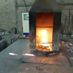
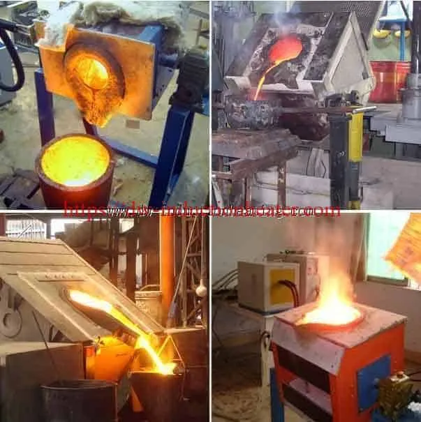



Metal Melting Furnace
Metal Melting Furnace for Steel, Copper, Aluminum and Precious Metals
What Is the Metal Melting Furnace?
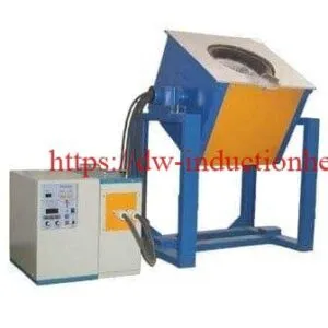
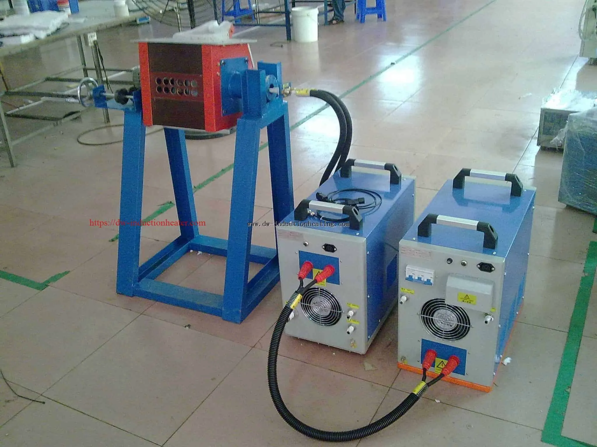
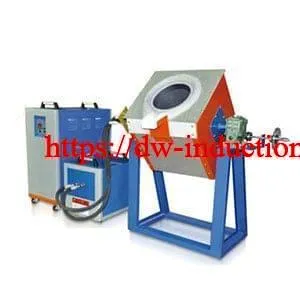
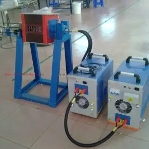
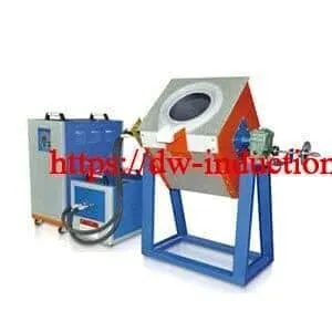
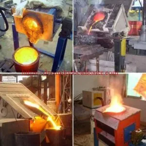
The HLQ DW-MF Metal Melting Furnace is an electrically powered,medium-frequency induction system designed to melt appropriately prepared conductive metals in a compatible crucible or refractory-lined vessel. It combines a DW-MF induction power generator, resonant compensation capacitors and an induction coil surrounding the melting chamber; the published package also lists a tilting furnace for pouring. The original HLQ series includes eight models, DW-MF-15 through DW-MF-160, with listed maximum input powers of 15–160kW and a series frequency range of 1–20kHz. It is best suited to small and medium batch melting in foundries, alloy workshops, metal-recycling operations and precious-metal casting where the furnace, crucible and process are selected for the actual alloy. Listed kilograms represent reference batch capacities, not independently verified production rates.
Quick Answer: Buyer and Engineer Summary
| Question | Practical Answer |
|---|---|
| What does the equipment do? | Melts conductive metals by electromagnetic induction and enables controlled preparation for pouring. |
| Which models are listed? | DW-MF-15, 25, 35, 45, 70, 90, 110 and 160. |
| What are the listed power and frequency ranges? | 15–160kW maximum input and 1–20kHz across the series; the final operating point is load-specific. |
| Which metals are explicitly quantified? | Steel/stainless steel, aluminum, and gold/silver in the original capacity table. |
| What must the buyer confirm? | Crucible dimensions, alloy compatibility, mean measured kW, tap-to-tap cycle, tilt drive, cooling and interlocks. |
| Is one furnace suitable for every metal? | No. Alloy chemistry, crucible, lining, temperature and contamination control can require different configurations. |
Key Distinction: Furnace Power, Capacity and Production
| Parameter | Meaning | Common Misinterpretation |
|---|---|---|
| Generator maximum input power (kW) | Published electrical power limit under defined conditions. | Not necessarily continuous thermal power absorbed by metal. |
| Batch capacity (kg) | Metal charge for a particular crucible/configuration. | Not kg per hour. |
| Melting energy (kWh/batch) | Total electricity measured over a defined boundary. | Not the metal’s thermodynamic minimum heat alone. |
| Tap-to-tap cycle (min) | Complete interval including charging, melting, preparation and pouring. | Not necessarily the generator energized time. |
Key Applications
Metal-melting duties vary by alloy family and downstream process.
The most useful configuration is the one that consistently meets
charge chemistry, safe pouring and accepted output—not simply the
highest nameplate power.
| Application | Typical Charge | Engineering Priority | Qualification Test |
|---|---|---|---|
| Small steel casting | Identified carbon or alloy steel | Refractory rating, bath temperature and slag handling | True kWh/t and tapping temperature |
| Stainless steel foundry batches | Segregated stainless grades | Alloy chemistry and crucible compatibility | Composition and lining inspection |
| Copper and bronze remelting | Clean copper, bronze ingots and returns | Oxidation, crucible coupling and temperature | Yield and surface quality after casting |
| Brass casting | Sorted brass and approved additions | Zinc fume capture and overheating avoidance | Fume control and chemistry loss |
| Aluminum casting | Dry aluminum ingots and clean scrap | Oxide/dross control and melt cleaning | Metal yield and inclusion control |
| Gold and silver casting | Verified precious-metal charges | Small-batch recovery and contamination avoidance | Assay and recovered metal mass |
| Prototype alloy development | Documented specialty compositions | Repeatable charge and thermal history | Batch record and chemical analysis |
For ferrous foundry equipment, review HLQ’s
induction furnaces for iron and steel melting
to compare larger refractory-lined designs.
Application-Specific Acceptance Metrics
| Process | Primary KPI | Secondary KPI | Risk to Manage |
|---|---|---|---|
| Ferrous melting | Tap temperature and chemistry | kWh/t and refractory life | Metal breakout and slag attack |
| Aluminum recycling | Accepted-metal yield | Dross mass per charge | Wet charge and entrained oxides |
| Copper alloys | Alloy composition | Oxidation loss | Overheating and fume generation |
| Precious metals | Mass balance / recovery | Assay consistency | Cross-contamination |
Suitable Materials
The DW-MF page names several metals, but it publishes explicit
capacity rows only for steel/stainless steel, gold/silver and aluminum.
Copper and bronze are valid induction-melting application categories;
however, their maximum batch weights are
not specified on this page.
Magnesium and similarly reactive metals must not be treated as
automatically suitable for an ordinary open crucible furnace.
| Material | Reference Phase-Change Temperature | Crucible / Process Concern | Verification |
|---|---|---|---|
| Carbon steel | Roughly 1425–1540°C depending on composition | High-temperature refractory, slag and superheat | Target tapping temperature and lining grade |
| Stainless steel | Roughly 1370–1530°C, grade dependent | Alloy retention and contamination | Alloy analysis and refractory compatibility |
| Cast iron | Composition-dependent melting range | Carbon/silicon control | Iron grade and furnace suitability |
| Copper | Pure copper about 1085°C | High conductivity and oxidation | Charge coupling, melt temperature and oxygen control |
| Brass / bronze | Wide composition-dependent range | Zinc losses for brass; melt chemistry | Ventilation and chemical analysis |
| Aluminum | Pure aluminum about 660°C | Oxide film, dross and alloy solidus/liquidus | Alloy-specific temperature setpoint |
| Gold / silver | Pure gold about 1064°C; silver about 962°C | Precious-metal recovery and crucible purity | Assay and clean segregated tools |
| Magnesium / reactive metals | Alloy-dependent | Ignition, protective atmosphere and dedicated safety systems | Separate engineered feasibility study |
For nonferrous melting, HLQ’s
copper induction melting furnace
page provides a different product configuration to consider.
Why Metal Properties Affect Induction Design
| Property | Effect on Heating | Design Response |
|---|---|---|
| Resistivity | Changes induced-current heating and electrical load | Recalculate matching at process temperature |
| Magnetic permeability | Ferrous magnetic behavior changes strongly with temperature | Account for the Curie transition |
| Melting enthalpy | Determines useful thermal energy required | Use alloy-specific enthalpy data |
| Density | Changes kilograms contained by a fixed crucible volume | Specify charge volume and safe freeboard |
| Oxidation tendency | May increase slag/dross and lower yield | Control charge, temperature and atmosphere |
Working Principle
A three-phase supply energizes a DW-MF generator, which delivers
medium-frequency AC to an electrical matching network and a
water-cooled induction coil. The alternating magnetic field induces
eddy currents in conductive metal and, in some configurations,
in a conductive crucible. Resistive losses create heat; as the
charge melts, electromagnetic forces can assist stirring.
The actual inverter circuit, current paths and coil/crucible coupling
must be confirmed against the supplied drawings.
Figure 1. Induction Melting System – Functional Principle
THREE-PHASE AC POWER
         |
         v
+-----------------------+
| DW-MF POWER GENERATOR |
+-----------------------+
         |
         v
+-----------------------+
| MATCHING CAPACITORS   |
+-----------------------+
         |
         v
+-----------------------+
| WATER-COOLED COIL     |
+-----------------------+
         |
 ALTERNATING MAGNETIC FIELD
         |
         v
+-----------------------+
| METAL / CRUCIBLE      |
| EDDY CURRENTS + HEAT  |
+-----------------------+
         |
         v
 MELTING -> TEMPERATURE CHECK -> POURING

SAFETY: WATER FLOW / ELECTRICAL INTERLOCKS / LINING CHECKS

Principle by Component
| Subsystem | Function | What Should Be Measured |
|---|---|---|
| Generator | Converts mains electricity to medium-frequency output | True input kW, kWh, frequency and input current |
| Capacitor network | Compensates reactive power and participates in resonant matching | Current, voltage and thermal condition |
| Induction coil | Creates alternating magnetic field | Water flow, pressure and temperature rise |
| Crucible / charge | Converts electromagnetic energy into melting heat | Charge mass and liquid-metal temperature |
| Mechanical pour system | Transfers molten metal to a safe receiving vessel | Loaded movement, pouring clearance and brake/stop behavior |
Figure 2. Heating and Heat-Loss Paths
                 MEASURED ELECTRICAL INPUT (kW)
                              |
              +---------------+---------------+
              |                               |
        GENERATOR LOSSES              POWER TO LOAD CIRCUIT
                                              |
                              +---------------+---------------+
                              |                               |
                        COIL / CABLE LOSSES             CHARGE HEATING
                                                              |
                                                     +--------+--------+
                                                     |                 |
                                                MELT ENTHALPY     WALL / COVER /
                                                                  HOLDING LOSSES

NOTE: THE METAL DOES NOT RECEIVE 100% OF THE NAMEPLATE INPUT.
Technical Specifications
The tables below reproduce the published DW-MF series ratings
while separating unclear or unverified claims.
The source labels 70–550V as “Input voltage” but separately specifies
a three-phase 380V ±10% mains supply; therefore, the 70–550V field
should not be used for mains wiring or voltage selection without
clarification. The original weight and dimension rows do not explicitly
identify which assembly is being weighed or measured.
General Technical Specifications
| Parameter | Specification | Notes |
|---|---|---|
| Product | DW-MF Metal Melting Furnace | HLQ published series |
| Power classes | 15, 25, 35, 45, 70, 90, 110, 160kW | Listed maximum input ratings, not guaranteed coil output |
| Supply | Three-phase 380V ±10%, 50/60Hz | Check destination electrical system |
| Published voltage field | 70–550V | Definition unclear; factory to confirm |
| Series frequency | 1–20kHz | Examples about 4/8/11/15/20kHz; load dependent |
| Duty statement | 100%, 24-hour work claimed | Requires defined cooling, ambient, maintenance and full-load test |
| Cold / hot melting time statement | 30–50min / 20–30min | No universal model, alloy, charge or temperature test conditions defined |
| Listed equipment | MF induction generator, tilting furnace, compensation capacitor | Confirm crucible, cooling and accessories in bill of supply |
| Coil cooling | Water cooling required | Model-specific flow and pressure not published |
| Crucible and furnace dimensions | Not established for each model | Request working volume, freeboard and mechanical drawings |
| Controller / tilting drive | Not fully specified | Request controller and actuator details |
Eight DW-MF Models and Published Reference Weights
| Model | Max. Input Power | Weight Listed | Frequency Statement |
|---|---|---|---|
| DW-MF-15 | 15kW | 50kg | 1–20kHz series range |
| DW-MF-25 | 25kW | 50kg | 1–20kHz series range |
| DW-MF-35 | 35kW | 65kg | 1–20kHz series range |
| DW-MF-45 | 45kW | 70kg | 1–20kHz series range |
| DW-MF-70 | 70kW | 80kg | 1–20kHz series range |
| DW-MF-90 | 90kW | 94kg | 1–20kHz series range |
| DW-MF-110 | 110kW | 114kg | 1–20kHz series range |
| DW-MF-160 | 160kW | 145kg | 1–20kHz series range |
Published Maximum Melting Ability by Material
| Model | Steel / Stainless Steel | Gold / Silver | Aluminum |
|---|---|---|---|
| DW-MF-15 | Not listed | 5kg or 10kg | 3kg |
| DW-MF-25 | 4kg or 8kg | 10kg or 20kg | 6kg |
| DW-MF-35 | 10kg or 14kg | 20kg or 30kg | 12kg |
| DW-MF-45 | 18kg or 22kg | 40kg or 50kg | 21kg |
| DW-MF-70 | 28kg | 60kg or 80kg | 30kg |
| DW-MF-90 | 50kg | 80kg or 100kg | 40kg |
| DW-MF-110 | 75kg | 100kg or 150kg | 50kg |
| DW-MF-160 | 100kg | 150kg or 250kg | 75kg |
Capacity qualification: “Or” alternatives may refer to
different crucible arrangements; they must be confirmed.
The source does not provide a copper/brass capacity table.
Maximum batch weight is not a throughput or metal-quality guarantee.
DW-MF-15 has no published steel number.

Figure 3. Published DW-MF Steel vs. Aluminum Capacity (Selected Models)
MODEL           STEEL, kg       ALUMINUM, kg

DW-MF-35        10 or 14            12
DW-MF-45        18 or 22            21
DW-MF-70        28                  30
DW-MF-90        50                  40
DW-MF-110       75                  50
DW-MF-160      100                  75

THE VALUES ARE REFERENCE BATCH CHARGES, NOT kg/h.
Recommended Model Selection
Choose the process and required batch mass first.
The table cross-references the source capacity information;
suggested models are preliminary and should be approved only after
the required crucible is confirmed and the exact alloy is tested.
| Application | Material | Recommended Power | Frequency |
|---|---|---|---|
| Small jewelry casting, 5–10kg listed | Gold / silver | DW-MF-15; 15kW max. input | Match the loaded crucible; published series 1–20kHz |
| Small steel batch, 4 or 8kg listed | Carbon / stainless steel | DW-MF-25; 25kW max. input | Measured load frequency required |
| Aluminum foundry, 12kg listed | Aluminum alloy | DW-MF-35; 35kW max. input | Verify crucible coupling and resonance |
| Small ferrous casting, 18 or 22kg listed | Steel | DW-MF-45; 45kW max. input | Verify at cold and molten stages |
| Aluminum remelting, 30kg listed | Aluminum | DW-MF-70; 70kW max. input | Load-specific within published series range |
| Ferrous foundry, 50kg listed | Steel | DW-MF-90; 90kW max. input | Confirm operating point during melt |
| Ferrous foundry, 75kg listed | Steel | DW-MF-110; 110kW max. input | Verify high-temperature matching |
| Ferrous batch, 100kg listed | Steel | DW-MF-160; 160kW max. input | Model- and crucible-specific trial |
For particularly contamination-sensitive precious-metal batches,
compare HLQ’s
induction gold and silver melting furnace solutions.
Model Selection by Practical Constraint
| Constraint | Preferred Engineering Action | Evidence Needed |
|---|---|---|
| Charge capacity | Confirm usable fill level and freeboard | Crucible volume and alloy density |
| Desired melts per shift | Calculate full tap-to-tap cycle | Demonstrated consecutive batches |
| Limited transformer | Check line current, true PF and harmonics | Electrical load study |
| High casting quality | Prioritize melt-cleaning and temperature control | Test castings and chemistry |
| Multiple alloys | Plan separate crucibles or qualified cleaning | Contamination-control procedure |
| High operating hours | Check rated thermal duty and cooling redundancy | Continuous-operation test |
Process Workflow
A reproducible melt requires controlled charge preparation,
a correctly warmed crucible, real energy measurement and a
documented pour. Water must never enter molten metal, and
moisture or sealed scrap must be excluded from furnace charging.
Figure 4. Production Workflow and Quality Gates
IDENTIFY ALLOY + WEIGH CHARGE
              |
              v
CHECK CHARGE DRYNESS + CONTAMINANTS
              |
              v
INSPECT CRUCIBLE / LINING / COOLING / INTERLOCKS
              |
              v
LOAD CHARGE + START INDUCTION POWER
              |
              v
MELT -> CHECK kW / kWh / COOLING / BATH
              |
              v
MEASURE TEMPERATURE + CHECK CHEMISTRY
              |
              v
APPROVE DRY RECEIVING LADLE + POURING ZONE
              |
              v
CONTROLLED POUR / TILT (IF SUPPLIED)
              |
              v
RECORD MASS / YIELD / TAP-TO-TAP / kWh
              |
              v
INSPECT AND RELEASE NEXT BATCH

Process Stage, Records and Acceptance
| Stage | Required Action | Documented Output |
|---|---|---|
| Pre-charge | Verify sorted alloy, dry charge and crucible | Charge ID, kilograms and inspection checklist |
| Electrical start | Check cooling, interlocks and electrical response | Start time, warnings, power trace |
| Melting | Monitor bath formation, slag/dross and power | kWh and process observations |
| Temperature/chemistry | Sample when required by product specification | Temperature and analysis result |
| Pouring | Confirm dry receiving system and exclusion zone | Pour time and gross metal mass |
| Closeout | Inspect lining, record yield and cycle | Accepted mass and tap-to-tap time |
Coil and Fixture Design
The electrical matching network, copper coil, crucible and structural support are one system. Coil turns and conductor section cannot be inferred from power alone; the cold charge, molten bath, crucible conductivity, actual load geometry and cooling arrangements must all be evaluated. The source lists a tilting furnace, but the exact tilting actuator and mechanical design are not specified for each model.
Coil, Crucible and Mechanical Design
| Component | Design Criterion | Common Risk |
|---|---|---|
| Copper coil | Current density, turn spacing, electrical insulation and cooling passages | Thermal damage, electrical short or water leak |
| Compensation capacitors | Actual inductance, voltage and reactive current | Mismatch or capacitor overheating |
| Crucible | Compatible material, load volume, clearance and freeboard | Chemical reaction, fracture or overflow |
| Refractory support | Temperature gradient and mechanical restraint | Thermal shock and metal breakout |
| Tilting axis and frame | Center of gravity and full-load rated support | Uncontrolled movement or pouring |
| Water hoses and power leads | Routing through full tilt travel without hot-surface contact | Fatigue, leaks or terminal strain |
| Ladle alignment | Pouring lip, clearance and safe metal stream | Spill, splash or excessive fall distance |
If the intended process is repeated aluminum pouring, review HLQ’s
tilting aluminum induction melting furnace
configuration.
Illustrative Water-Side Cooling Calculation
For ordinary water,
Q(kW) = 1.163 x flow(m3/h) x temperature rise(C).
This is a water-side heat balance, not a statement of required
chiller size for any DW-MF model.
| Illustrative Flow | Temperature Rise | Heat Carried Away | Design Interpretation |
|---|---|---|---|
| 2m3/h | 5°C | 11.6kW | Verify coil versus generator branch allocation |
| 4m3/h | 5°C | 23.3kW | Pump head and water quality still matter |
| 6m3/h | 5°C | 34.9kW | Check actual measured heat losses |
| 8m3/h | 5°C | 46.5kW | Do not infer sufficient cooling from flow alone |
Critical Safety Verification
| Potential Hazard | Preventive Engineering Measure | Evidence |
|---|---|---|
| Wet or sealed charge | Charge inspection and approved dryness procedure | Operator checklist and training |
| Coil-water leakage | Flow monitoring, leak inspection and correct emergency response | Commissioning and periodic test |
| Crucible/lining failure | Correct lining, inspection and defined replacement criterion | Maintenance log |
| Uncontrolled tilt | Travel limits, rated drive, holding mechanism and exclusion zone | Loaded tilt function test |
| Fumes and particulates | Alloy-appropriate extraction and filtration | Ventilation design and maintenance |

Control System and Automation
The source does not provide a comprehensive PLC or communication
specification. The following is an engineering configuration checklist;
only functions expressly shown on the agreed equipment schedule
should be described as standard.
| System Feature | Purpose | Supply / Test Requirement |
|---|---|---|
| Adjustable power | Control melting, superheat and holding | Document actual continuous regulation range |
| True kW and kWh recording | Measure electricity consumed per charge | Use suitable metering with logged power factor |
| Temperature instrumentation | Confirm tapping temperature | Alloy-appropriate calibrated method |
| Frequency and load monitoring | Track resonant performance as bath changes | Record hot/cold values |
| Electrical protections | Limit overcurrent, phase and converter faults | Factory-provided trip setpoints and tests |
| Water branch interlocks | Detect loss of critical cooling | Test actual protective response |
| Tilting control | Manage controlled pour if tilt is supplied | Loaded, stopped and power-loss tests |
| PLC/HMI recipes and reports | Batch traceability and production consistency | Optional unless specified in the order |
Recommended Foundry Data Log
| Recorded KPI | Unit | Purpose |
|---|---|---|
| Incoming charge | kg | Traceable energy denominator |
| Purchased electrical input | kWh/batch | Measured energy cost |
| Tap-to-tap cycle | min | Actual output capacity |
| Accepted liquid/finished metal | kg | Yield-adjusted production |
| Tap temperature | °C | Casting quality and superheat |
| Water supply / return | °C, flow | Cooling reliability |
| Energy per accepted ton | kWh/t | Apples-to-apples batch comparison |
Common Problems and Solutions
| Problem | Likely Cause | Engineering Action |
|---|---|---|
| Melting time exceeds the quoted reference | Lower mean real kW, cold lining, large charge or elevated tap temperature | Measure mean input power and full-cycle energy on the actual alloy. |
| Generator trips as charge melts | Changing resonant load, abnormal current or component fault | Follow isolated diagnostic procedure; inspect matching network and coil. |
| Excessive scale or dross | Long holding, contaminated charge or excessive temperature | Reduce unnecessary superheat; improve sorting and melt practice. |
| Crucible cracks | Thermal shock or incompatible refractory | Replace damaged crucible; qualify material and heat-up procedure. |
| Unexpected chemistry | Mixed alloys, contamination or volatilization | Segregate charge and utensils; analyze samples. |
| Coil or cables overheat | Low water flow, blocked passages or high reactive current | Stop heating safely; measure local flow and inspect electrical loading. |
| Fume concentration rises | Alloy overtemperature or inadequate extraction | Improve temperature control and verified ventilation. |
| Metal spills during pour | Unstable tilting, incorrect ladle location or poor pouring lip | Stop operation and revalidate mechanics and pouring geometry. |
| High energy per kilogram | Small charge, excessive idle time or low yield | Measure kWh per accepted ton; optimize batch sequence. |
| Water alarm with hot furnace | Low flow, pump failure or leakage | Apply approved emergency shutdown and residual-cooling plan. |
Engineering Selection Guide
Evaluate each proposed furnace against the same boundary conditions:
charge mass, composition, initial temperature, tapping temperature,
actual measured electrical input, cold/hot state, yield and the
complete time between successive taps.
1. Preliminary Specific Electricity Consumption
Use measured customer data when available.
The following illustrative planning intervals
are not guaranteed DW-MF performance and vary substantially
with charge geometry, furnace losses, metal temperature
and batch size.
| Material | Illustrative Electrical Consumption | Dominant Variables |
|---|---|---|
| Steel / stainless steel | 650–950kWh/t | Cold furnace, superheat, refractory and tapping practice |
| Aluminum | 350–550kWh/t | Charge form, oxide/dross and holding time |
| Copper and copper alloys | 350–600kWh/t | Crucible coupling, oxidation and metal temperature |
| Gold / silver | Factory-test data required | Small-batch surface-area losses and crucible material |
Energy (kWh) = charge mass (tonnes) x measured or assumed
specific electricity (kWh/t).
Example: 50kg of steel at an assumed 800kWh/t uses
0.050 x 800 = 40kWh at the chosen system boundary.
2. Estimate Energized Melting Time
Energized time (minutes) =
60 x electrical energy (kWh) / sustained mean real input power (kW).
The rated maximum input kW is not necessarily the mean kW delivered
throughout a melt. The following assumes, only for calculation,
mean input equal to 80% of the listed model maximum.
| Illustrative Scenario | Assumed Energy | Mean Input (Hypothetical) | Calculated Energized Time |
|---|---|---|---|
| 10kg steel; DW-MF-35 | 8.0kWh at 800kWh/t | 28kW | 17.1min |
| 28kg steel; DW-MF-70 | 22.4kWh at 800kWh/t | 56kW | 24.0min |
| 50kg steel; DW-MF-90 | 40.0kWh at 800kWh/t | 72kW | 33.3min |
| 100kg steel; DW-MF-160 | 80.0kWh at 800kWh/t | 128kW | 37.5min |
| 30kg aluminum; DW-MF-70 | 13.5kWh at 450kWh/t | 56kW | 14.5min |
| 75kg aluminum; DW-MF-160 | 33.75kWh at 450kWh/t | 128kW | 15.8min |
These are hypothetical energy-balance examples only; neither the
80% power factor used for mean loading nor the electrical consumption
values have been tested for these HLQ models. The calculations exclude
separate handling and pouring delays and should not be quoted as
production guarantees.
Figure 5. 100kg Steel: Mean Input Power vs. Energized Time
ASSUMED ELECTRICITY: 80kWh FOR 100kg STEEL

 MEAN REAL INPUT           CALCULATED TIME

  80kW    ##############################  60 min
 100kW    ########################        48 min
 120kW    ####################            40 min
 128kW    ###################             37.5 min
 160kW    ###############                 30 min

ILLUSTRATIVE ONLY; kWh AND REAL INPUT MUST BE MEASURED.
3. Determine Good-Metal Throughput
Gross kg/h = 60 x charge kg / tap-to-tap minutes.
Good-metal kg/h also depends on yield.
Examples below assume a 95% accepted-metal yield,
not measured performance.
| Assumed Charge | Assumed Tap-to-Tap | Gross kg/h | Good kg/h at 95% Yield |
|---|---|---|---|
| 10kg | 30min | 20 | 19 |
| 28kg | 45min | 37.3 | 35.5 |
| 50kg | 50min | 60 | 57 |
| 75kg | 60min | 75 | 71.3 |
| 100kg | 65min | 92.3 | 87.7 |
4. Estimate Electricity Cost per Accepted Tonne
For budgeting,
electricity cost per accepted tonne =
measured kWh per batch x electricity tariff /
accepted mass in tonnes
.
At a hypothetical tariff of USD 0.12/kWh, 100kg of steel
requiring 80kWh and yielding 95kg acceptable metal gives
USD 9.60 per batch or approximately USD 101 per accepted tonne,
excluding labor, consumables and capital costs.
| Cost Element | Example / Unit | What to Include |
|---|---|---|
| Electrical energy | kWh/batch | Measured whole melting duty |
| Electricity tariff | Currency/kWh | Actual utility rate and any demand charges |
| Consumables | Currency/batch | Crucible, refractory, flux and melt-treatment materials |
| Accepted metal | kg/batch | Exclude dross, slag and rejected output |
| Labor and handling | Currency/batch | Charging, sampling, tilting and cleaning |
5. Verify Site Electrical Supply
For a balanced three-phase source,
S(kVA) = 1.732 x line voltage(V) x line current(A) / 1000
and
real input kW = S x true power factor
.
The examples below assume a power factor of 0.90 solely for
arithmetic; they are not DW-MF factory current specifications.
| Assumed Real Input | PF | Apparent Power | Calculated Line Current at 380V |
|---|---|---|---|
| 25kW | 0.90 | 27.8kVA | 42A |
| 45kW | 0.90 | 50.0kVA | 76A |
| 90kW | 0.90 | 100.0kVA | 152A |
| 160kW | 0.90 | 177.8kVA | 270A |
6. Factory Acceptance Test (FAT)
| Test Element | Required Evidence | Acceptance Basis |
|---|---|---|
| Equipment identification | Exact model, nameplate, scope, electrical drawing | Agreed purchase specification |
| Charge and alloy | Weighed representative metal and documented chemistry | Customer production material |
| Electrical performance | True kW, kWh, frequency, current and power factor | Corrected factory electrical data |
| Melting time | Cold and hot cycles with identical boundaries | Agreed energized and tap-to-tap timing |
| Product quality | Temperature, composition and accepted yield | Customer casting requirements |
| Cooling | Individual branch flow, temperature and alarms | Manufacturer limits and tests |
| Tilting, if applicable | Loaded pour, stops, brakes and power-loss behavior | Safe mechanical demonstration |
Advantages
| Potential Advantage | Production Value | Qualification |
|---|---|---|
| Direct induction heat | Energy is generated in metal or a compatible conductive crucible | Coupling and whole-system efficiency vary |
| Multiple power classes | Eight published models for varied batch sizes | Different metal-specific capacities |
| Compact batch processing | Suitable for precision casting and small foundry workshops | Check actual layout and ventilation |
| Controllable heat input | Can manage melting and superheat with proper controls | Confirm real regulation range |
| Possible electromagnetic stirring | Can improve mixing in a suitable molten bath | Depends on metal, field and crucible geometry |
| Data-driven improvement | Measured kWh/t and yield reveal operating losses | Requires accurate instrumentation |
Limitations
| Limitation | Why It Matters | Engineering Response |
|---|---|---|
| Unclear 70–550V field | Conflicts with explicit 380V mains statement | Obtain corrected model datasheet before wiring |
| Unqualified generic melt-time claim | Cannot guarantee 20–30min across all charges | Test metal-specific cold and hot cycles |
| Copper/brass capacities absent | No source-backed maximum batch weight | Request matched crucible test and quotation |
| Reactive alloys | Open equipment may be unsuitable or unsafe | Design specialized atmosphere and fire protection |
| Cooling-dependent operation | Flow loss threatens coil and electronics | Use properly tested safety interlocks |
| Crucible contamination | One lining may not suit every alloy | Separate or qualify crucibles and tooling |
| Batch rather than continuous output | kg per charge is not kg/h | Calculate accepted-metal tap-to-tap productivity |
| Molten-metal hazards | Moisture, splashes and breakouts can be severe | Maintain dryness, refractory integrity and trained operation |

Why Choose HLQ Induction Equipment?
HLQ supplies medium-frequency induction generators and industrial melting systems. A technically useful quotation should match the DW-MF generator to the chosen metal, crucible, bath dimensions, cooling circuit and pouring arrangement. Instead of relying on a generic claim of rapid or energy-saving melting, request measured kWh per accepted ton, verified tap-to-tap productivity and a documented cooling and safety test using your own charge material.
For a related system emphasizing an electrically driven pouring arrangement, compare HLQ’s
electric induction melting furnace with a tilting device.
Customer RFQ Checklist
| Buyer Information | Required Detail | Why It Is Needed |
|---|---|---|
| Material | Alloy grade, charge condition, segregation and scrap size | Defines crucible and heating strategy |
| Charge size | kg/batch and largest individual piece | Determines working volume |
| Production rate | Accepted kg/h, shifts/day and target cycle | Determines true capacity |
| Process temperature | Initial and tapping temperature | Determines energy and metallurgy |
| Electrical site | Voltage, 50/60Hz, available kVA and protection | Determines plant compatibility |
| Cooling | Water supply temperature, quality, pressure and flow | Protects power and coil system |
| Pouring method | Ladle size, receiving elevation and automation preference | Determines mechanical configuration |
| Acceptance requirements | kWh/t, melt time, quality and yield | Turns claims into measurable performance |
Core FAQs
FAQ 1. What is an induction metal melting furnace?
It is an electrically powered furnace that uses alternating magnetic fields to induce heating currents in conductive metal or in a compatible conductive crucible. The HLQ DW-MF series is intended for appropriately configured batch melting and casting preparation.
FAQ 2. Which DW-MF models are available?
The original HLQ page lists DW-MF-15, DW-MF-25, DW-MF-35, DW-MF-45, DW-MF-70, DW-MF-90, DW-MF-110 and DW-MF-160, with maximum listed electrical input ratings from 15 to 160kW.
FAQ 3. Can the furnace melt copper, brass, aluminum and steel?
These conductive metals are candidates for induction melting when the furnace, crucible and operating procedure are compatible. The original model table provides capacity figures for steel/stainless steel, aluminum and gold/silver but does not establish copper or brass batch maxima.
FAQ 4. What melting capacity is published for DW-MF-160?
The source lists 100kg of steel/stainless steel, 75kg of aluminum and 150kg or 250kg of gold/silver. The alternative precious-metal weights require exact crucible-configuration confirmation. These are reference batch sizes, not hourly production guarantees.
FAQ 5. How long does one metal-melting batch take?
The original page describes approximately 30–50 minutes on a cold start and 20–30 minutes for later warm-furnace melts. These are generic references without defined alloy, complete charge, tapping temperature or measured mean input power; actual time should be established by repeatable tests.
FAQ 6. What is the appropriate medium-frequency setting?
The published DW-MF series mentions 1–20kHz and several typical frequencies. The correct operating point depends on coil geometry, capacitance, metal resistivity, cold/hot load conditions and crucible design; not every frequency is necessarily available for every charge.
FAQ 7. How is a cooling system selected?
Calculate the heat rejected to each water circuit and confirm flow, pressure, supply temperature and required water quality with the actual equipment. A water-side heat balance is Q(kW) ≈ 1.163 × flow(m3/h) × temperature rise(°C), but this alone does not specify the complete chiller
or cooling-tower design.
FAQ 8. What should buyers include in a factory acceptance test?
Use weighed representative material and record cold/warm starts, true electrical input kW and kWh, frequency, tapping temperature, total cycle time, accepted metal yield, cooling performance and safety interlocks. If tilting is included, test loaded movement, stops and controlled pouring under approved conditions.