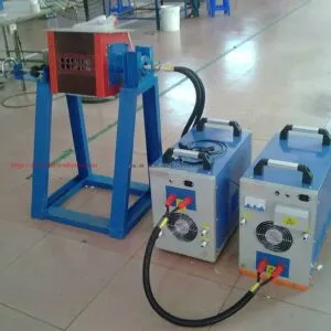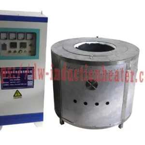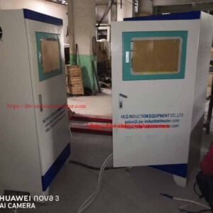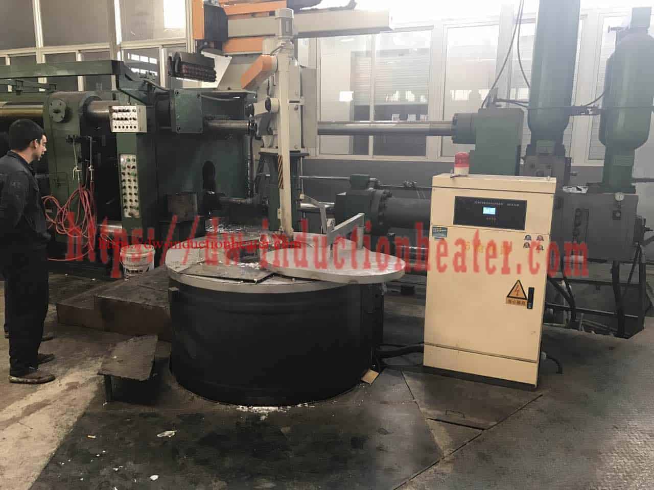


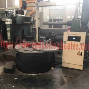
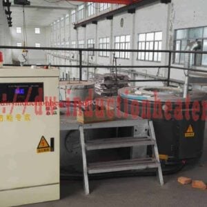

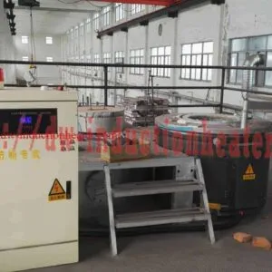
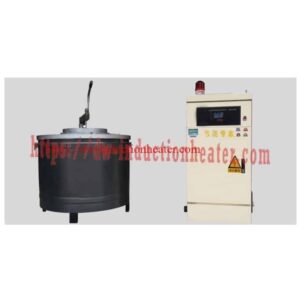
Magnetic Induction Aluminum Melting Furnace-Machine
Magnetic Induction Aluminum Melting Furnace for Foundry Modernization
Quick Answer: The HLQ magnetic induction aluminum melting furnace is an electrically powered system for remelting clean aluminum ingots, casting alloys, and suitably prepared foundry returns. The published JLRRL series includes 150 kg, 300 kg, and 500 kg nominal charge models with listed powers of 30, 60, and 70 kW and melting rates of 65, 130, and 170 kg/h, respectively. Its main engineering value is controllable electromagnetic heating for repeatable foundry operation. Before purchasing, verify the exact induction frequency, power rating basis, usable crucible volume, temperature measurement method, and a documented melt test.
Best-fit use: Aluminum foundries upgrading older fuel-fired or resistance-heated equipment, alloy casting workshops requiring repeatable batches, and facilities seeking measurable production and energy data. 
Table of Contents
- What is the Magnetic Induction Aluminum Melting Furnace?
- Key Applications
- Suitable Materials
- Working Principle
- Technical Specifications
- Recommended Model Selection
- Process Workflow
- Coil and Fixture Design
- Control System and Automation
- Common Problems and Solutions
- Engineering Selection Guide
- Advantages
- Limitations
- Why Choose HLQ Induction Equipment?
- Core FAQs
What is the Magnetic Induction Aluminum Melting Furnace?
A magnetic induction aluminum melting furnace uses an inverter-driven, water-cooled copper coil to create an alternating magnetic field that heats a conductive aluminum charge and/or its compatible conductive crucible. The equipment is particularly suitable for foundry melting and furnace modernization where a controlled electrical process, traceable energy consumption, and predictable pouring temperatures are desired. It does not, by itself, refine contaminated scrap or replace alloy analysis, degassing, and casting equipment.
HLQ’s JLRRL range on this product page is presented as three nominal batch sizes. The product uses the term magnetic induction to describe electromagnetic induction; it does not mean that aluminum must be ferromagnetic. Aluminum is a nonferromagnetic but electrically conductive metal, so proper load coupling, crucible selection, and inverter matching are critical.
| Buyer Question | Direct Answer | Required Verification |
|---|---|---|
| What is the process? | Induction melting of aluminum and selected alloys | Grade, feed form, target pouring temperature |
| What JLRRL sizes are published? | 150 / 300 / 500 kg nominal batch capacity | True molten-metal working volume and safe freeboard |
| What performance is listed? | 65 / 130 / 170 kg/h nominal melting rates | Cold or hot start, charge size, measured input kWh |
| Is it a complete casting system? | No; casting, filtration, degassing and transfer are project-dependent | Scope of supply and acceptance tests |
Key Applications
The same furnace can be considered for several aluminum processes, but each has different quality controls. For an upgrade project, compare complete production workflows rather than only a heater’s nameplate power.
| Application | Feedstock | Primary KPI | Design Priority |
|---|---|---|---|
| Gravity and sand casting | Certified alloy ingots and clean returns | Repeatable pour temperature | Batch scheduling and alloy identification |
| Die-casting metal supply | Al-Si alloys | Consistent liquid-metal delivery | Melting and holding system balance |
| Fuel-fired furnace modernization | Known aluminum alloy | Total operating cost per good kg | Utility capacity and measured baseline |
| Resistance furnace replacement | Clean ingots and casting returns | Melt cycle and process response | Cooling, coil maintenance and control logic |
| Controlled scrap remelting | Dry, separated industrial scrap | Metal yield and kWh per poured kg | Scrap inspection and dross management |
| Alloy pilot batches | Identified alloy components | Temperature/chemistry repeatability | Crucible changeover and sample procedure |
Facilities focused on scrap preparation and recovery should compare the aluminum scrap recycling furnace process requirements before assuming all scrap forms can be charged directly.
For a dedicated clean-charge process, see HLQ’s aluminum ingots induction melting furnace application.
Suitable Materials
Pure aluminum melts at approximately 660.3°C, but aluminum alloys melt over composition-dependent temperature intervals. A higher furnace maximum does not justify overheating every charge. The stated 850°C maximum on the published JLRRL table should be checked for each model and is not a universal pouring setpoint.
| Material | Preliminary Suitability | Process Constraint |
|---|---|---|
| Commercial-purity aluminum ingots | Primary use | Dry and correctly identified charge |
| Al-Si foundry alloys | Generally suitable | Alloy-specific liquidus, Mg control, treatment plan |
| A356 / AlSi7Mg | Suitable following a melt trial | Hydrogen, oxide bifilms, chemistry and treatment |
| Clean gates and risers | Usually suitable when alloy-separated | Metal yield and contamination records |
| Clean aluminum extrusion offcuts | Conditional | Verify alloy identification and scrap-to-product chemistry |
| Painted, oily or wet aluminum scrap | Do not charge without approved pretreatment | Explosion, fumes, emissions and dross risks |
| Thin beverage cans | Requires dedicated engineering review | High surface-area oxidation and coating removal |
| Aluminum dross | Not equivalent to metallic charge | Separate recovery system and realistic recovery yield |
| Reference Point | Temperature | Meaning |
|---|---|---|
| Pure aluminum phase change | About 660.3°C | Fundamental material property |
| Illustrative molten aluminum operating band | About 680-760°C | Actual target is alloy- and casting-dependent |
| JLRRL published maximum | 850°C | Check rating and sensing position by model |
Working Principle
The electrical supply feeds an IGBT-based inverter and resonant matching circuit. Alternating current in the copper induction coil generates a changing magnetic field. Induced currents heat the metallic charge and, for some designs, the crucible or conductive susceptor. Furnace insulation retains useful heat; controls adjust delivered power as the charge warms and melts.
| Step | Component | Function | Engineering Check |
|---|---|---|---|
| 1 | Grid / switchgear | Supplies electrical energy | Input voltage, phase, kVA and protection |
| 2 | IGBT inverter | Creates high-current AC | Rated input versus output kW; inverter duty |
| 3 | Resonant matching | Optimizes coil/load energy transfer | Actual operating frequency in kHz |
| 4 | Water-cooled coil | Generates magnetic field | Turn geometry, insulation and coolant interlock |
| 5 | Crucible and charge | Absorbs heat and melts | Material compatibility and correct fill level |
| 6 | Control system | Regulates power and alarms | Temperature sensor location and failsafe response |
Engineering note: Induction frequency is not the 50/60 Hz supply frequency. The original target page mentions phase-locked frequency tracking but does not publish an exact JLRRL output frequency. A numerical frequency must therefore be supplied by HLQ as a model-specific design value. HLQ’s broader medium-frequency induction heating system portfolio describes power-supply families, but the figures must not automatically be transferred to these aluminum furnace models.
Technical Specifications
| Parameter | JLRRL-150 | JLRRL-300 | JLRRL-500 |
|---|---|---|---|
| Published rated power | 30 kW | 60 kW | 70 kW |
| Nominal aluminum batch capacity | 150 kg | 300 kg | 500 kg |
| Published melting rate | 65 kg/h | 130 kg/h | 170 kg/h |
| Maximum temperature | 850°C shown in source table | Confirm applicability | Confirm applicability |
| Listed crucible inner diameter x height | 42 x 67 cm | 53 x 65 cm | 63 x 72 cm |
| Overall listed dimensions | 1240 x 1210 x 980 mm | 1400 x 1370 x 980 mm | 1570 x 1540 x 1080 mm |
| No-load heat-up time | <1.5 h shown in first row | Not separately listed | Not separately listed |
| Exact induction operating frequency | Not published | Not published | Not published |
| Rated supply V / phase / current | Not published | Not published | Not published |
| Cooling flow / pressure / inlet temp | Not published | Not published | Not published |
Published-data qualification: The page does not establish whether the 30/60/70 kW values are electrical input or delivered power; it also lacks test conditions for its kg/h numbers. Some cells in the original table are blank or merged, so shared values must be confirmed rather than copied into every model as fact.
| Parameter | Specification | Notes |
|---|---|---|
| Power conversion | IGBT / inverter-based induction heating claimed | Request detailed power-converter datasheet |
| Power regulation | Closed-loop adjustment and frequency tracking claimed | Verify power readout against calibrated meter |
| Temperature control | PID and digital controller claimed | Confirm bath sensor, setpoint tolerance and calibration |
| Temperature accuracy | Claim of up to ±3°C appears on source page | Do not treat as guaranteed molten-bath accuracy without FAT |
| Protection | Voltage, phase, current, temperature and leakage alarms claimed | Confirm safety functions, wiring and trip tests |
| Duty cycle | 24-hour / full-load operation claimed | Subject to ambient, cooling, maintenance and operating duty |
| Insulation | High-temperature fiber structure described | Ask for hot-face lining material, life and wear limits |
| Cooling | Water-cooling requirements to be specified | Mandatory design review for coils and electronics |
Recommended Model Selection
Use published nominal performance only as a starting screen. Actual selection should be based on poured good-metal kg/h, charge type, production uptime, metal temperature, utility limits, crucible headspace, and downtime allowance.
| Application | Material | Recommended Power | Frequency |
|---|---|---|---|
| Workshop production at or below 65 kg/h nominal | Dry ingots / clean cast returns | 30 kW (JLRRL-150 published candidate) | Exact model kHz to be confirmed |
| Foundry operation at or below 130 kg/h nominal | Specified aluminum cast alloys | 60 kW (JLRRL-300 published candidate) | Exact model kHz to be confirmed |
| Large batch with rate up to 170 kg/h nominal | Ingot / prepared foundry returns | 70 kW (JLRRL-500 published candidate) | Exact model kHz to be confirmed |
| 250 kg/h continuous production requirement | Aluminum alloy / clean returns | Custom design; listed single units do not claim this rate | Engineered with coil and load |
| Multi-shift line needing spare capacity | Known alloy mix | Parallel furnaces or higher-power system | Project-specific |
| Model | Published kg/h | Nominal batch kg | Capacity / Rate | Interpretation |
|---|---|---|---|---|
| JLRRL-150 | 65 | 150 | 2.31 h | Not a measured cold-start batch time |
| JLRRL-300 | 130 | 300 | 2.31 h | Compare trial run and pouring cycle |
| JLRRL-500 | 170 | 500 | 2.94 h | Larger pot does not imply faster hourly output |
Process Workflow
Production sequence: Confirm alloy and charge weight → inspect/dry scrap → inspect crucible and cooling → establish safe water flow → load approved charge → apply induction power → verify bath temperature and chemistry → treat/skim molten metal → pour into dry, prepared equipment → record kWh, kg and cycle time.
| Stage | Production Task | Hold Point / Acceptance |
|---|---|---|
| Incoming material | Verify alloy, coatings, moisture and sealed items | Dry, sorted and accepted charge |
| Start-up | Inspect coil, vessel, lining, guard and cooling | Permissives and shutdown circuits checked |
| Melting | Maintain controlled power and charge addition | Correct current, alarms and metal level |
| Bath quality | Measure temperature, sample chemistry, degas if specified | Alloy-specific pouring criteria met |
| Pouring | Use approved dry ladle or tilting system | Safe pour path and no water contamination |
| Measurement | Log energy, charge and good poured mass | Traceable kWh/kg, yield, downtime and defects |
Coil and Fixture Design
For nonferromagnetic aluminum, the coil-to-load system and the crucible material strongly affect electromagnetic coupling. A correctly sized coil must maintain electrical isolation while allowing expansion of the hot vessel, consistent cooling and safe pouring. Design review should address copper conductor dimensions, active height, coil turns, resonant matching, structural support and access for lining replacement.
| Part | Design Requirement | Evidence Needed |
|---|---|---|
| Coil | Turns / current / clearance fit the aluminum load | Approved section drawing and operating range |
| Crucible | Compatible with aluminum and alloying additives | Material grade, life expectation and replacement part |
| Thermal insulation | Protect coil while minimizing heat loss | Layer schedule and drying/curing procedure |
| Freeboard | Adequate headspace for charging, wave action and handling | Marked maximum allowable liquid height |
| Pouring fixture | Stable geometry and controlled pouring | Load test, guards and limit interlocks |
| Cooling-water circuit | Avoid overheating and water intrusion near the bath | Flow, leak protection, alarms and routing drawings |
Crucible-volume screening: If the published diameters and heights are treated as perfect internal cylinders, their calculated geometric volumes are about 92.8, 143.4 and 224.5 liters. Assuming illustrative liquid aluminum density of 2.37 kg/L, the nominal charge masses imply approximately 68%, 88% and 94% of this geometry. Real crucibles taper, have bottom curvature and require freeboard: the 500 kg configuration in particular needs a signed working-volume and maximum-fill drawing.
| Model | Ideal Cylinder (L) | Charge Volume (L) | Implied Fraction | Required Follow-up |
|---|---|---|---|---|
| JLRRL-150 | 92.8 | 63.3 | 68% | Confirm true vessel shape |
| JLRRL-300 | 143.4 | 126.6 | 88% | Confirm safe freeboard |
| JLRRL-500 | 224.5 | 211.0 | 94% | Recheck effective fill capacity before ordering |
Control System and Automation
Automation is valuable when it makes temperature and power histories reproducible rather than simply adding a touch screen. The page mentions PID control, tracking and fault displays, but the delivered I/O list, sensor type, accuracy and optional PLC/HMI functions must be documented individually. A bath-immersion temperature measurement is generally more directly representative than an uncorrected surface infrared reading.
| Control Function | Why It Matters | Acceptance Test |
|---|---|---|
| Inverter power command | Repeatable ramp and hold recipes | Setpoint versus independently measured power |
| Frequency tracking | Matches changing furnace load | Recorded frequency across cold/hot charge |
| Temperature PID | Controls superheat and holding | Calibrated bath probe comparison at target temperature |
| Flow / temperature interlocks | Protects water-cooled system | Prove safe trip and controlled restart |
| Leak and electrical fault handling | Reduces escalation after a fault | Reviewed alarm matrix and safety circuit |
| PLC / HMI recipes | Operator consistency and traceability | Optional scope; signed I/O and recipe list |
| Historian / kWh meter | Verifies operating economics | Time-stamped charge, poured kg and metered kWh |
| Modbus / PROFINET interface | Foundry MES integration | Optional protocol and point-list verification |
Common Problems and Solutions
| Problem | Likely Cause | Recommended Solution |
|---|---|---|
| Actual melt rate below nominal | Cold start, underpower, poor matching or dirty charge | Measure kW, kg and initial conditions in a representative run |
| Excess dross | High temperature, dirty thin scrap, long holding | Sort/dry charge, reduce excess superheat and holding duration |
| Temperature oscillation | Sensor placement, PID tune, inconsistent charge | Calibrate bath measurement and retune after process review |
| High electricity per good kg | Idle loss, low yield, low utilization, hot standby | Track production-state energy and net good-metal output |
| Power supply trips | Cooling, voltage, current or resonant matching fault | Stop heating, capture alarm, qualified service diagnosis |
| Cooling alarm | Blocked circuit, scale, pump problem, warm water | Restore specified flow/temperature; check leak risk |
| Crucible wear or crack | Thermal shock, unsuitable material or impact | Replace/repair to OEM method; no operation with damaged vessel |
| Metal chemistry variation | Mixed scrap, burnout of alloying elements | Segregate alloys and sample before pour |
| Splash or eruption | Wet charge or trapped liquid | Stop charging; enforce dry-charge SOP and PPE |
Engineering Selection Guide
1. Distinguish rated power from measured energy consumption
The source page publishes 30, 60 and 70 kW with 65, 130 and 170 kg/h, respectively. Dividing these pairs gives simple ratios of 0.462, 0.462 and 0.412 kWh/kg. These are nameplate-power-to-listed-rate arithmetic, not independently metered electricity use: the power boundary, loading factor, starting condition and molten-metal mass basis have not been defined.
| Model | Published kW | Published kg/h | kW ÷ (kg/h) | Data Status |
|---|---|---|---|---|
| JLRRL-150 | 30 | 65 | 0.462 kWh/kg | Screening ratio only |
| JLRRL-300 | 60 | 130 | 0.462 kWh/kg | Screening ratio only |
| JLRRL-500 | 70 | 170 | 0.412 kWh/kg | Screening ratio only |
2. Establish a realistic thermal-energy baseline
U.S. Department of Energy engineering references place the ideal minimum energy to melt pure aluminum from around room temperature at approximately 0.30 kWh/kg. Actual purchased electricity also heats the crucible and refractory and covers power-supply loss, radiation, holding and process inefficiencies. Compare measured energy at the same alloy, pouring temperature, yield and production schedule.
| Required Net Melt Rate | 0.45 kWh/kg | 0.60 kWh/kg | 0.75 kWh/kg |
|---|---|---|---|
| 65 kg/h | 29.3 kW | 39.0 kW | 48.8 kW |
| 130 kg/h | 58.5 kW | 78.0 kW | 97.5 kW |
| 170 kg/h | 76.5 kW | 102.0 kW | 127.5 kW |
| 250 kg/h | 112.5 kW | 150.0 kW | 187.5 kW |
The three specific-energy cases above are planning scenarios only. A final quote must state whether kWh/kg is measured at the incoming electrical meter, per charged mass, per liquid metal, or per good casting. Different measurement boundaries produce different results.
3. Compare a furnace retrofit on identical production boundaries
When considering replacement of a diesel, gas, or resistance furnace, benchmark total cost per good kilogram, not a headline power-saving percentage. Include purchased energy, useful poured-metal yield, labor, flux, dross, lining and coil replacement, ventilation, cooling, start-up/holding losses and expected availability.
| Metric | Existing Furnace Baseline | Proposed Induction System | How to Compare |
|---|---|---|---|
| Net good metal kg/h | Plant production log | Guaranteed test basis | Same alloy and melt quality |
| Energy per good kg | Fuel meter or electric meter | Electric input kWh meter | Convert all fuel to consistent money and energy units |
| Metal yield | Charged versus accepted kg | Charged versus accepted kg | Include dross and rejects |
| Operators per shift | Actual labor | Proposed staffing | Include charging and pouring labor |
| Consumables and maintenance | Burners, elements, lining | Crucible, coil, electronics, cooling | Annualized, realistic replacement intervals |
| Emissions / ventilation | Combustion and process capture | Process fumes and heat extraction | Check site permit and indoor environment |
4. Calculate payback with transparent assumptions
Simple payback (years) = Net project capital expenditure / Annual verified operating savings. For example, a hypothetical retrofit costing US$50,000 net that genuinely saves US$12,500 annually has a simple payback of 4 years. This is not an HLQ quote or promised saving; it excludes financing, tax, production ramp-up and time value of money.
| Annual Verified Saving | Simple Payback | Decision Use |
|---|---|---|
| US$5,000/year | 10.0 years | Reassess utilization and lifecycle risk |
| US$10,000/year | 5.0 years | Compare to site investment threshold |
| US$12,500/year | 4.0 years | Hypothetical base scenario |
| US$20,000/year | 2.5 years | Requires documented savings and uptime |
5. Define the factory acceptance test
| Item | Required Evidence | Pass / Fail Basis |
|---|---|---|
| Process target | Metal grade, kg/batch, kg/h, pour temperature | Signed duty point |
| Power and input | Nominal input V/A/kVA; metered electrical kWh | Electrical supply within site limits |
| Frequency | Measured or documented operating kHz | Model-specific inverter/coil match |
| Crucible geometry | Actual hot-face dimensions and safe fill mark | Required batch within approved freeboard |
| Cooling | Flow, pressure, inlet temperature and fault response | Verified operating range and loss-of-flow trip |
| Temperature | Immersion probe/calibrated sensor comparison | Agreed pour-temperature repeatability |
| Melting performance | Timed representative charge and metered input | Guaranteed kg/h and kWh/kg boundary |
| Safety | Interlocks, emergency stop, written charging/pouring SOP | Documented functional test |
Advantages
| Potential Advantage | Why It Matters | Condition |
|---|---|---|
| No burner flame at the melting vessel | Changes combustion-related workplace exposure | Metal fumes and ventilation remain necessary |
| Adjustable electromagnetic power | Fast response to process recipe changes | Requires correct inverter and control tuning |
| Repeatable logged operation | Supports quality assurance and optimization | Metering and data collection must be specified |
| Potential process-energy savings | Can reduce total operating costs in suitable retrofits | Validate against a fair, measured baseline |
| Automation integration options | Supports controlled production and traceability | PLC/MES interfaces may be extra-cost options |
| Compact furnace footprint | Potential improvement to workshop layout | Allow safe service and pouring clearances |
Limitations
| Limitation | Engineering Consequence | Mitigation |
|---|---|---|
| Unverified energy-saving percentage | 20-40% published promotional claim lacks comparable duty data | Meter same plant processes before and after |
| Nominal batch is not hourly capacity | 500 kg pot still lists 170 kg/h | Size to required good-metal kg/h |
| Exact output frequency unpublished | Cannot approve coil/inverter compatibility from web data alone | Request signed kHz specification |
| Cooling is critical | Coil failure and water ingress create severe hazards | Interlocks, routing and prevention controls |
| High apparent geometric fill for large model | 500 kg screening fill ≈94% of ideal cylinder | Confirm real freeboard and lining shape |
| Melt does not equal refined product | Dross, gas and inclusions remain possible | Use qualified melt-treatment and QC procedure |
| Grid demand and harmonics | May require electrical distribution upgrades | Site electrical study and measured power-quality review |
Why Choose HLQ Induction Equipment?
HLQ Induction Equipment Co., Ltd. offers induction heating and melting solutions for metalworking. The basis for an informed purchasing decision should be its ability to supply application-specific coil and furnace designs, complete utility requirements, clear controls documentation, consumables support, and a repeatable factory melt test. Broad efficiency or precision statements must be converted into specific acceptance criteria before purchase.
| Deliverable | Minimum Content | Purchaser Benefit |
|---|---|---|
| Formal equipment datasheet | Input/output kW, voltage, kHz, safe batch kg | Comparable quotations |
| General arrangement drawing | Crucible geometry, total size, service and pouring clearances | Site planning and capacity verification |
| P&ID and interlocks | Coolant, alarms, electrical/safety logic | Safe commissioning |
| Documented melt trial | Charge, kg/h, kWh, temperature, yield | Real productivity benchmark |
| Maintenance and spare list | Crucible, lining, coil, cooling consumables | Lifecycle costing |
| Automation scope | HMI/PLC options, communications and data registers | Future integration |
If the process requires more controlled transfer to a ladle or holding vessel, discuss an induction melting furnace with a tilting device. For a wider comparison of furnace sizes and materials, review HLQ’s industrial induction furnace portfolio.
Technical inquiry: Send the required alloy grade, production rate (kg/h), largest batch, feed form, electrical supply, target pouring temperature and available cooling-water conditions to HLQ Induction Equipment Co., Ltd. via its official website contact form.
Core FAQs
1. What is a magnetic induction aluminum melting furnace?
It is an electrically powered furnace that uses an alternating magnetic field to heat a conductive aluminum charge and/or a suitable susceptor crucible. It is useful for controlled aluminum casting and foundry remelting.
2. Can magnetic induction heat nonmagnetic aluminum?
Yes. Aluminum is nonferromagnetic but electrically conductive; induced currents can heat it. Power transfer depends on geometry, frequency, temperature, and the crucible configuration.
3. Which JLRRL models are listed?
The target HLQ page lists JLRRL-150, JLRRL-300 and JLRRL-500 with 150, 300 and 500 kg nominal capacities.
4. What are the published power ratings?
30, 60 and 70 kW, respectively. The original listing does not clearly state the measurement boundary for these kW values; confirm whether each is rated input or output.
5. What melt rates are advertised?
65, 130 and 170 kg/h, respectively. The melt-test conditions are not supplied, so request a representative factory trial.
6. What operating frequency is used?
The exact JLRRL induction output frequency is not published. It must not be confused with 50/60 Hz mains frequency or inferred from another product line.
7. Can this furnace replace a gas or diesel aluminum furnace?
Potentially, but confirm site electrical capacity, required molten output, melting-versus-holding duty, cooling, ventilation and pouring systems. Compare total cost per accepted kilogram using actual plant data.
8. Does an induction furnace always save 20-40% energy?
No. The target page includes that promotional range without documented test boundaries. Savings depend on the existing furnace, utilization, yield, setpoint, downtime and electricity/fuel cost.
9. How much electricity is theoretically required to melt aluminum?
Approximately 0.30 kWh/kg is a commonly cited ideal minimum for pure aluminum from around room temperature to its melting point. Actual purchased electricity is greater and must be measured for each operation.
10. Is the maximum temperature 850°C for every model?
850°C appears in the source specification table, but merged or blank cells make model-specific applicability unclear. Obtain a signed datasheet before treating it as a universal rating.
11. Is a 500 kg furnace suitable for 500 kg/h production?
Not on the published data: the JLRRL-500 has a nominal 500 kg batch capacity but only a stated 170 kg/h melting rate.
Aluminium Scraps Recycling Melting Process
SMJD induction melting furnace parameter
Aluminum,Copper,Iron Induction Melting Furnace manual