




Magnetic Grinding Machine
Magnetic Grinding Machine for Precision Deburring and Polishing
What Is the Magnetic Grinding Machine?
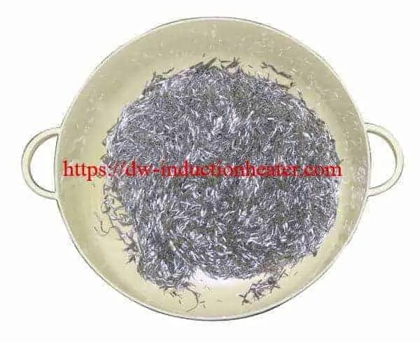
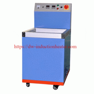
The HLQ Magnetic Grinding Machine, also called a magnetic deburring and polishing machine, is a batch surface-finishing system that drives small magnetically responsive stainless-steel pins through a work bowl using a changing magnetic field. The pins contact accessible part surfaces to remove light burrs, reduce minor machining marks, clean recesses and improve appearance. Its best-fit applications are small, intricate components such as CNC-turned fittings, stamped parts, jewelry findings, precision hardware and parts with accessible slots or holes. It is a finishing process, not an induction heater or a substitute for heavy stock-removal grinding. Final results require application trials.
| Buyer question | Direct engineering answer |
|---|---|
| What does it do? | Light deburring, polishing, cleaning and controlled edge conditioning. |
| How does it work? | A changing magnetic field moves magnetic stainless-steel pins in a liquid-filled bowl. |
| Best parts? | Small intricate parts with fine burrs and surfaces accessible to pins and liquid. |
| Typical cycle? | The existing HLQ page describes approximately 5-20 minutes; not a guaranteed result. |
| What must be tested? | Burr removal, surface finish, dimensions, media entrapment, cleanliness and total cycle cost. |
Key Applications
Magnetic pin finishing is useful where rigid brushes, files or buffing wheels cannot consistently reach fine features. Effectiveness is controlled by pin geometry, part accessibility, cycle intensity and the original burr condition.
| Application | Typical component | Objective | Acceptance check |
|---|---|---|---|
| CNC machined parts | Turned fittings, collars, connectors | Remove small cross-hole and edge burrs | Burr-height inspection; visual and tactile check |
| Stamped components | Clips, brackets, small shims | Reduce fine stamping burrs | Edge condition and part distortion |
| Jewelry and ornaments | Findings, chains, decorative parts | Brighten reachable features | Appearance, scratches and detail retention |
| Watch and eyewear parts | Small precision hardware | Finish edges and crevices | Dimensional and appearance inspection |
| Electronic and telecom hardware | Metal terminals, sleeves, housings | Remove fine burrs and residue | Particle and contact-area cleanliness |
| Medical-device components | Selected instrument parts | Light deburring before cleaning | Validated bioburden/particle and dimensional process |
| Die castings | Small nonferrous cast parts | Remove fine flash and brighten | Remaining heavy flash; porosity exposure |
For an alternative product presentation, compare HLQ’s
magnetic deburring and polishing machine
page.
Suitable Materials
The workpiece itself does not need to be magnetic: the magnetic field primarily drives the finishing pins. Ferromagnetic workpieces, delicate coatings and mixed-material assemblies can behave differently and require trials.
| Material | Indicative suitability | Major risk / validation item |
|---|---|---|
| Stainless steel | Often suitable for fine burrs | Surface finish, passivation compatibility, pin contamination |
| Copper and brass | Often suitable for gentle finishing | Soft-metal marking, discoloration, compound compatibility |
| Aluminum alloy | Trial required | Scratch risk, softness and staining |
| Carbon steel / ferrous parts | Trial required | Magnetic attraction, parts sticking, corrosion control |
| Silver / gold jewelry alloys | Often considered for fine polishing | Detail retention, plating and gemstone protection |
| Rigid engineering plastics | Application-specific | Scratches, dimensional or edge damage |
| Coated / plated parts | Restricted until tested | Coating thinning, micro-scratches, peeling |
| Assemblies with bearings or seals | Generally require special evaluation | Trapped media, ingress, magnetic exposure |
Working Principle
A magnetic drive underneath or around a nonmagnetic processing bowl produces a moving magnetic field. The field exerts forces and torques on magnetically responsive stainless-steel pins, causing them to tumble, rotate and contact part surfaces in water with an appropriate finishing compound. Repeated light impacts and rubbing can remove small burrs and brighten accessible surfaces. The original page does not establish whether this particular HLQ unit uses rotating permanent magnets or electronically driven electromagnets; that implementation must be confirmed.
        WORKPIECE + WATER + FINISHING COMPOUND

                       +------------+
                       |  PARTS     |
                       |  . . . .   |  <-- moving magnetic pins
                       |   . . .    |
                       +------------+

                         NONMAGNETIC BOWL

                 ~ ~ ~ CHANGING MAGNETIC FIELD ~ ~ ~

                       MAGNETIC DRIVE

                           CONTROLLER

                Timer / drive setting / safety interlock
Unlike a cutting wheel, the pins do not remove large amounts of stock. Deep blind holes, undersized openings or geometries that trap pins may remain incompletely finished; access must be demonstrated on samples.
| Process variable | Expected influence | Verification |
|---|---|---|
| Pin diameter and length | Feature access and contact aggressiveness | Fit through minimum passage; no retained pins |
| Magnetic drive intensity | Media motion and finishing action | Part damage and burr removal |
| Batch mass and fill | Part-to-media interaction | No overloading or excessive part collision |
| Liquid level and compound | Lubrication, cleaning and corrosion control | Supplier-approved concentration and quality |
| Processing duration | Deburring extent and scratch risk | Stop when acceptance criteria are met |
Technical Specifications
The source page describes the process and a reference processing period but does not provide a numeric machine datasheet. Unknown ratings are shown as not published instead of inferred from unrelated HLQ induction generators.
| Parameter | Specification | Notes |
|---|---|---|
| Product | Magnetic Grinding / Deburring / Polishing Machine | HLQ published product name |
| Finishing medium | Magnetically responsive stainless-steel pins | Pin grade, dimensions and mass not specified |
| Processing mechanism | Magnetic-field-driven pin motion | Drive architecture not specified |
| Typical application cycle | Approximately 5-20 minutes | Original page’s indicative range; sample-dependent |
| Target operations | Fine deburring, polishing, cleaning, light edge finishing | Does not guarantee zero dimensional change |
| Typical workpieces | Small precision parts, jewelry, complex metal components | Suitable batch confirmed by trials |
| Motor / electrical rated power | Not published | Request certified nameplate kW |
| Input voltage / phase / frequency | Not published | Confirm for destination country |
| Magnetic drive speed / frequency | Not published | Distinct from mains frequency or induction heating frequency |
| Working bowl dimensions / volume | Not published | Request working rather than gross capacity |
| Maximum batch mass | Not published | Confirm usable load for actual parts |
| Machine dimensions / net weight | Not published | Confirm footprint and installation |
| Pin consumption / change interval | Not published | Monitor damage and contamination |
| Control range / timer resolution | Not published | Original page mentions adjustable operation |
| Machine guarding / electrical protections | Not detailed | Confirm with current machine documentation |
| Surface roughness guarantee | Not published | Define baseline and final Ra/Sa by testing |
Recommended Model Selection
HLQ’s reviewed page does not publish named machine variants or validated wattages. Use the following application matrix to define the power class to be quoted and the magnetic drive settings to be tested; do not treat it as an existing HLQ model catalog.
| Application | Material | Recommended Power | Frequency |
|---|---|---|---|
| Jewelry findings / micro hardware | Gold, silver, brass | Specify after bowl load and trial | Drive-specific; request adjustable setting range |
| Small CNC turned parts | Stainless steel, brass | Specify after batch-mass trial | Not published; validate drive intensity |
| Stamped precision components | Stainless, mild steel, copper | Size for fill level and component collision risk | Drive-specific; not a kHz heating rating |
| Fine die castings | Aluminum, zinc alloy | Sample test required for surface sensitivity | Drive-specific; tune with approved settings |
| Higher-volume batch finishing | Sorted compatible components | Confirm motor kW and maximum effective batch load | Confirm manufacturer controller specification |
Compare the full
magnetic grinding machine range
before selecting the production system.
Machine Selection: Required Data from Manufacturer
| Requirement | Buyer should request | Why it matters |
|---|---|---|
| Net usable batch mass | kg of actual parts per cycle | Defines production capacity |
| Bowl working dimensions | mm / usable liters | Confirms workpiece fit and part mobility |
| Pin kit | Diameter, length, grade, initial mass | Confirms hole access and contact behavior |
| Rated electric power | kW, V, phase, Hz, current | Correct electrical design |
| Magnetic drive | Type and adjustable speed/intensity | Process control |
| Process fluid | Water / compound recipe and waste handling | Quality and safety |
| Acceptance | Representative before/after sample report | Technical and commercial proof |
Process Workflow
Production should follow an approved finishing recipe with measurable entry and exit criteria.
Inspect parts and burrs
        |
        v
Select compatible magnetic pins + liquid / compound
        |
        v
Set batch weight, loading arrangement and test cycle
        |
        v
Magnetic pin finishing (initial trial: 5-20 min reference)
        |
        v
Separate and account for ALL pins
        |
        v
Rinse / clean / dry parts
        |
        v
Inspect burrs, finish, dimensions and cleanliness
        |
        +---- Not acceptable? --> Adjust recipe; repeat controlled trial
        |
        v
Record approved process recipe and release batch
| Stage | Check | Record |
|---|---|---|
| Incoming inspection | Material, burr location and condition | Part ID, drawing and initial defect photos |
| Loading | Batch mass, pin quantity, fluid level | Mass and selected recipe |
| Processing | Time, speed/intensity, mixing behavior | Actual cycle time and operating setting |
| Separation | All pins recovered; no trapped media | Media-accountability result |
| Cleaning/drying | Compound residue and corrosion risk | Rinse and drying method |
| Quality control | Burrs, surface, dimensions, particles | Measured pass/fail result |
Coil and Fixture Design
Terminology note: A magnetic grinding machine does not necessarily use an induction-heating coil or a heated workpiece. For this process, the relevant design is the magnetic drive, processing bowl, pin media and part-separation fixture. Coil details apply only if the supplied magnetic drive actually uses electromagnets, which the reviewed HLQ page does not establish.
Magnetic Pins and Feature Accessibility
| Design item | Engineering check | Consequence if incorrect |
|---|---|---|
| Pin diameter | Smaller than accessible openings with adequate clearance | Cannot enter feature or becomes trapped |
| Pin length | Compatible with passage depth and intersections | Bridging or jammed media |
| Pin grade / magnetism | Compatible with magnetic drive and material cleanliness | Weak motion or contamination |
| Bowl geometry | No persistent stagnant or overloaded zones | Nonuniform finishing |
| Part separation | Prevent part-to-part collision for delicate parts | Scratches and distortion |
| Media recovery | Magnetic tool / sieve and accountable pin removal | Retained foreign material |
| Fluid compatibility | Approved chemistry for alloy and coating | Staining and corrosion |
See also the
magnetic polishing machine application collection
for related HLQ product references.
Control System and Automation
The original page mentions adjustable operation, timing and cycle-completion reminders, but it does not publish a controller datasheet. Request verification of available speed/intensity settings, reversal modes, recipes and safety protections for the exact machine supplied.
| Control / feature | Recommended function | Documentation status |
|---|---|---|
| Cycle timer | Repeatable dwell time and end-of-cycle alarm | Function mentioned; numeric controller range absent |
| Drive intensity | Adjust pin agitation for part sensitivity | Available range must be confirmed |
| Drive direction / reversal | Improve coverage if supported | Not confirmed for HLQ model |
| Lid / bowl guarding | Prevent access during operation | Confirm current safety design |
| Overload / thermal protection | Protect motor and electronics | Not documented on reviewed page |
| Recipe management | Store part-specific approved settings | Optional integration, confirm availability |
| Operator traceability | Batch records, alarms and inspection status | Requires site-specific integration |
Process Quality Dashboard: Values to Record
| KPI | Unit | Pass criterion |
|---|---|---|
| Remaining burr height | mm or µm | Per drawing and validated inspection |
| Surface roughness | Ra or Sa, µm | Per customer specification |
| Critical dimensions | mm | Within drawing tolerance |
| Media retention | Count | Zero retained pins where specified |
| Batch processing time | min | Qualified process window |
| Finished acceptable parts | pieces/batch | Verified yield |
Common Problems and Solutions
| Problem | Possible cause | Practical corrective action |
|---|---|---|
| Fine burr remains | Wrong pin size, short time, insufficient access | Review burr type and pin access; test controlled recipe |
| Blind hole not clean | Pins cannot circulate in deep cavity | Check depth/diameter, part orientation and alternative process |
| Visible scratches | Excessive intensity, overload, sharp media or collision | Reduce intensity/load; inspect media; use protective separation |
| Edges rounded too much | Excessive processing or aggressive pin selection | Shorten cycle and specify measurable edge criteria |
| Part color changes | Unsuitable compound, dirty water or alloy response | Change to approved chemistry; rinse and dry promptly |
| Pins trapped in features | Pin length matches bore / crevice geometry | Change media dimensions; introduce pin accountability |
| Parts clump together | Ferromagnetic attraction or high fill | Reduce batch; use separation fixtures; confirm feasibility |
| Inconsistent finish | Variable batch weight / water level / cycle | Standardize the process recipe and part orientation |
| Heavy burr is unaffected | Process is for fine finishing, not heavy machining defects | Pre-deburr mechanically then apply magnetic finishing |
| Water residue / corrosion | Incomplete rinsing/drying or improper chemistry | Validated post-cleaning and drying; corrosion inhibitor if appropriate |
| Low hourly throughput | Slow unloading, separation and inspection | Measure total cycle, not just machine timer |
Engineering Selection Guide
Specify the finishing outcome first and the machine second. A purchase decision should be based on representative production samples, not just machine size or the ability to make a sample look shiny.
Step 1. Define the Acceptance Criteria
| Requirement | How to specify it | Recommended measurement |
|---|---|---|
| Burr removal | Maximum remaining burr height and location | Optical microscope / profile measurement |
| Surface finish | Target Ra/Sa and inspection zone | Profilometer / surface imaging |
| Edge condition | Maximum edge radius or minimum sharpness | Optical measurement |
| Dimensional stability | Critical features and tolerances | Calipers, CMM or suitable gauge |
| Cleanliness | Residual media / particles / chemistry | Visual, filtration or customer method |
Step 2. Separate Machine Time from Total Production Time
For batch finishing: Good parts per hour = 60 × accepted parts per batch / total batch cycle (minutes). The complete cycle includes loading, finishing, separation, washing, drying and inspection.
| Processing time | Other handling time | Total cycle | Theoretical batches/hour |
|---|---|---|---|
| 5 min | 4 min | 9 min | 6.7 |
| 10 min | 4 min | 14 min | 4.3 |
| 15 min | 4 min | 19 min | 3.2 |
| 20 min | 4 min | 24 min | 2.5 |
These are mathematical examples using an assumed four-minute handling allowance; no HLQ machine throughput is claimed.
5-min finishing:   #####|####              =  9 min total
10-min finishing:  ##########|####         = 14 min total
15-min finishing:  ###############|####    = 19 min total
20-min finishing:  ####################|#### = 24 min total

                    finishing | handling

Note: illustration, not an HLQ performance test.

Step 3. Run a Controlled Trial Matrix
| Trial | Machine dwell | Other conditions | Decision data |
|---|---|---|---|
| A | 5 min | Same parts, media, liquid and drive setting | Burr, finish, dimensions, pin trapping |
| B | 10 min | Hold all other variables constant | Incremental change vs. A |
| C | 15 min | Hold all other variables constant | Incremental change vs. B |
| D | 20 min | Use only if shorter trials fail and parts remain safe | Evidence of over-processing |
Choose the shortest qualified cycle, then confirm repeatability across multiple batches. For regulated components, apply a documented process validation plan.
Step 4. Supplier RFQ Checklist
| Provide to HLQ | Example of required detail |
|---|---|
| Material | Grade, heat treatment and coating |
| Part drawing | Overall dimensions, smallest bore and deepest blind hole |
| Burr specification | Photos, height, location and cause |
| Surface requirement | Before/after Ra or visual sample standard |
| Batch requirement | Parts/hour, pieces/batch, current manual cost |
| Installation requirements | Voltage, frequency, available space and utilities |
| Inspection requirement | Measurement method and customer acceptance limits |
Advantages
| Potential benefit | How it helps | Qualification |
|---|---|---|
| Reaches complex geometry | Pin media can enter accessible holes and crevices | Not every blind feature is accessible |
| Batch processing | Multiple small components can be finished together | Capacity depends on geometry and batch load |
| Reduced manual contact | Less hand filing and buffing during the timed stage | Loading and inspection remain necessary |
| Flexible materials | Applicable to several metal alloys | Trials required for soft/coated parts |
| Combined finishing | Fine deburring, cleaning and brightening in one stage | Does not replace all upstream machining |
| Repeatable recipe potential | Controlled batch weight, media and time | Prove with repeatable sample results |
Limitations
| Limitation | Practical implication | Alternative / mitigation |
|---|---|---|
| Heavy burrs and thick flash | Slow or ineffective removal | Mechanical pre-deburring or machining |
| Very deep blind holes | Media may not circulate | Geometry trial or targeted finishing |
| Small critical holes | Media may become trapped | Pin-size review and 100% media checks |
| Ferromagnetic workpieces | Part attraction and clustering | Reduced load, fixtures, sample test |
| Soft or plated components | Scratches or coating damage | Gentle recipe or alternative process |
| Strict dimensional tolerances | Material removal / edge change possible | Pre/post dimensional measurements |
| Environmental claims | Wastewater and spent chemistry still need treatment | Document waste and water management |
| Missing machine ratings | Cannot guarantee batch kg/h or electrical setup | Obtain model datasheet and factory trial report |
Why Choose HLQ Induction Equipment?
HLQ offers magnetic grinding and deburring equipment for precision component finishing. For a reliable purchase, ask HLQ to provide a model-specific datasheet, a compatible magnetic-pin kit, clear electrical requirements, sample-processing results and repeatable acceptance criteria. The right machine is the one that meets the drawing requirements with acceptable batch throughput, cleanliness and surface condition; a faster or brighter-looking result is not automatically a better result.
For related topic collections, browse HLQ’s
magnetic deburring machine applications.
Recommended Factory Acceptance Test
| Acceptance element | Evidence to request |
|---|---|
| Machine identity | Model, serial number, electrical nameplate |
| Parts | Representative customer samples and quantities |
| Recipe | Media type/size, mass, compound, liquid, dwell and drive setting |
| Before / after | Microscope images, surface roughness, dimensional results |
| Yield | Accepted parts per batch and repeatability |
| Media recovery | No retained pins under agreed detection method |
| Safety | Guarding, emergency stop and current compliance documents |
FAQ – Eight Engineering Questions
FAQ 1. What is a magnetic grinding machine?
It is a batch deburring and polishing machine that uses a changing magnetic field to drive fine magnetic stainless-steel pins around small workpieces in a liquid-filled bowl. The pins perform gentle surface contact and are most useful for fine burrs and intricate, accessible features.
FAQ 2. Is magnetic grinding the same as induction heating?
No. Magnetic pin finishing uses magnetic forces to move finishing media; it is not designed to raise a workpiece to forging or melting temperature. The word “magnetic” refers to pin movement, not induction heating performance.
FAQ 3. Can magnetic pins finish internal holes and threads?
They can improve reachable holes, cross-drillings and threads when pin size, part geometry and motion permit access. Deep blind holes and narrow features may remain unfinished or trap pins, so representative samples must be inspected.
FAQ 4. What materials can be processed?
Depending on the finishing recipe, suitable candidates include stainless steel, brass, copper, aluminum alloys, some ferrous components, precious-metal jewelry alloys and selected rigid plastics. Ferromagnetic workpieces, coatings and very soft parts need additional testing.
FAQ 5. How long does a magnetic polishing cycle take?
The reviewed HLQ page describes approximately 5-20 minutes. Actual time depends on burr size, part geometry, pin selection, batch mass and target finish. Include loading, pin separation, rinsing, drying and inspection when calculating hourly output.
FAQ 6. Will magnetic polishing change part dimensions or round edges?
Any mechanical finishing process can change surface topography and edge geometry. For tight-tolerance parts, compare critical dimensions, edge radius and surface roughness before and after trials; do not assume zero change.
FAQ 7. What power and magnetic drive frequency does the HLQ machine use?
The current published product page does not supply model-specific rated power, electrical input, motor speed or magnetic drive frequency. Request the exact machine datasheet. Do not confuse the magnetic pin drive frequency with the 1-20 kHz rating of HLQ’s separate induction heating generators.
FAQ 8. How should buyers select and validate a magnetic deburring machine?
Submit representative components with dimensions, burr photos, surface-finish targets, throughput needs and inspection limits. Perform controlled trials, document the process recipe, measure the finish and dimensions, confirm complete pin recovery and accept the machine only after the results are repeatable.