
Induction Shaft Hardening Machine For Pins,Shafts and Rods
What Is an Induction Shaft Hardening Machine?
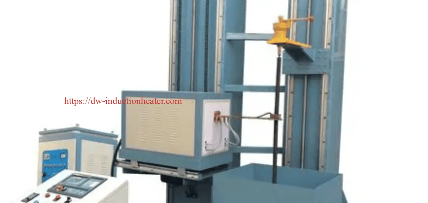
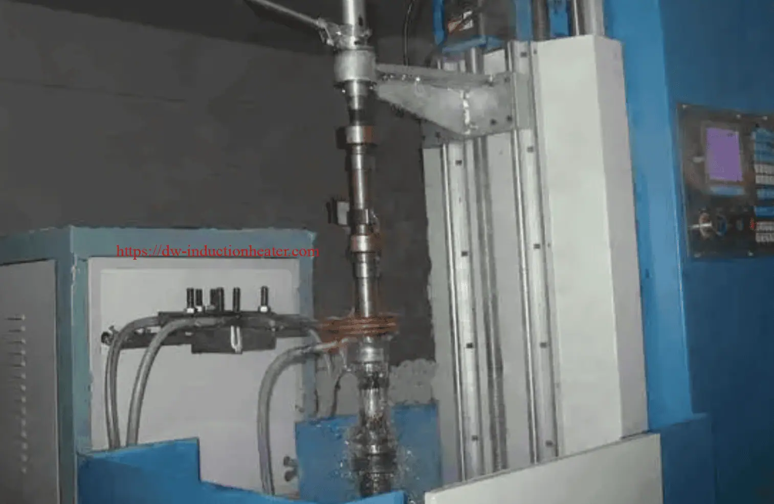
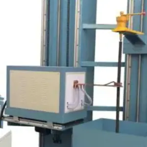
An induction shaft hardening machine is a specialized induction heat treatment system used to harden the surface of cylindrical metal parts. The equipment uses an induction power supply, copper induction coil, CNC scanning mechanism, quenching system and control system to complete localized heating and rapid cooling.
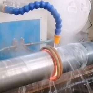
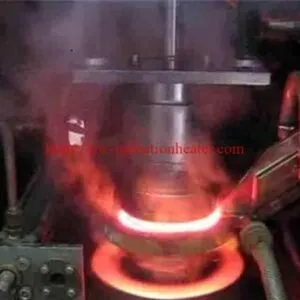
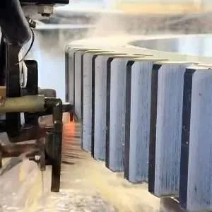
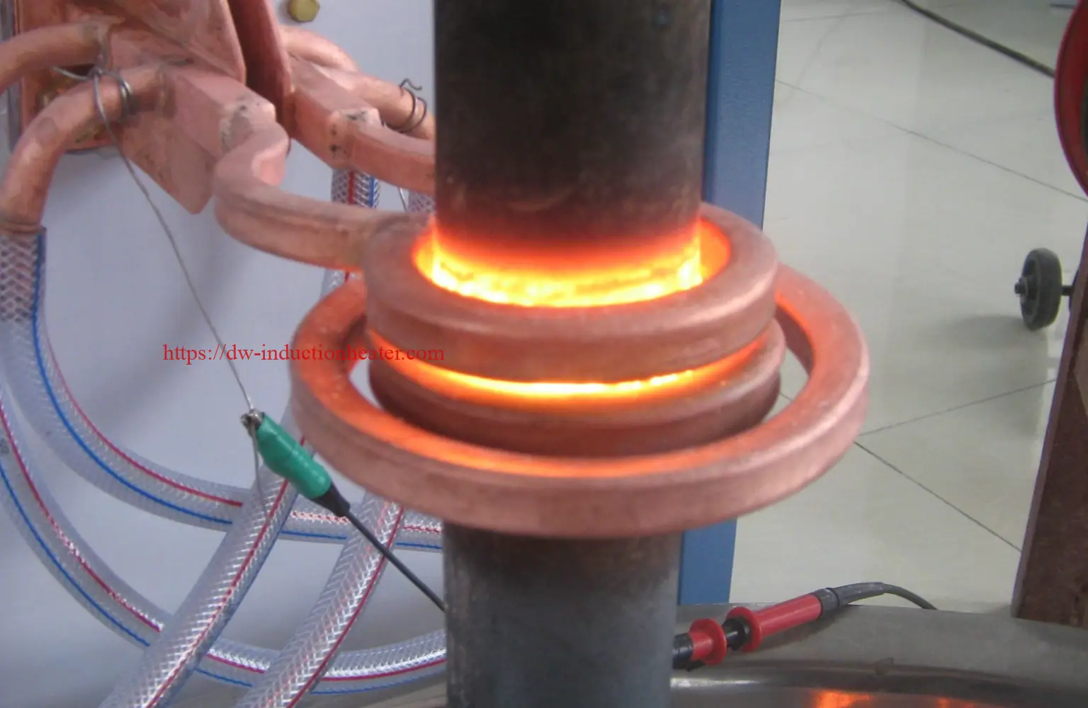
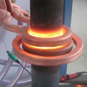
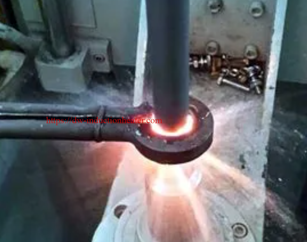
During the process, the shaft, pin or rod is positioned inside or near the induction coil. Alternating current flows through the coil and generates a high-frequency electromagnetic field. This field induces eddy currents on the surface of the metal part, rapidly heating the surface layer to the required hardening temperature. After heating, the part is immediately quenched by water, polymer solution or other quenching media to form a hardened martensitic layer.
The result is a component with a hard, wear-resistant surface and a tough inner core. This combination is especially important for shafts and rods that must resist friction, bending, torsion, impact and long-term fatigue.
Key Applications
The induction shaft hardening machine is widely used for surface hardening of round, cylindrical and rotating components.
Typical Workpieces
|
Workpiece Type |
Common Application |
Hardening Requirement |
|---|---|---|
|
Steel shafts |
Motors, gearboxes, pumps, machinery |
Wear resistance and fatigue strength |
|
Pins |
Construction machinery, hinges, connectors |
Surface hardness and impact resistance |
|
Rods |
Hydraulic cylinders, guide systems, linear motion |
Smooth hardened surface and low distortion |
|
Axle shafts |
Automotive and agricultural machinery |
High fatigue strength |
|
Spline shafts |
Transmission systems |
Tooth and surface wear resistance |
|
Motor shafts |
Electric motors and industrial drives |
Long service life |
|
Guide rods |
Machine tools and automation equipment |
Straightness and surface durability |
|
Crankshafts |
Engines and compressors |
Localized journal hardening |
|
Camshafts |
Automotive engines |
Wear resistance on working surfaces |
|
Gear shafts |
Gearboxes and transmission systems |
Combined shaft and gear tooth hardening |
Suitable Materials
Induction shaft hardening is mainly used for carbon steel, medium carbon steel, alloy steel and some cast iron materials.
|
Material |
Suitability |
Notes |
|---|---|---|
|
1045 / C45 steel |
Excellent |
Common for shafts and rods |
|
4140 / 42CrMo steel |
Excellent |
Suitable for high-strength mechanical parts |
|
40Cr steel |
Excellent |
Common in automotive and machinery shafts |
|
5140 steel |
Good |
Suitable for transmission components |
|
4340 steel |
Good |
Used for heavy-duty shafts |
|
Bearing steel |
Good |
Requires precise process control |
|
Ductile iron |
Conditional |
Depends on carbon content and structure |
|
Stainless steel |
Limited |
Some grades require special evaluation |
|
Low carbon steel |
Limited |
Usually needs carburizing or special treatment |
For best results, the material should contain enough carbon to form a hardened martensitic surface after heating and quenching. Medium carbon steels such as C45, 1045, 40Cr and 42CrMo are among the most common materials for induction shaft hardening.
How Does the Induction Shaft Hardening Process Work?
The induction shaft hardening process is based on electromagnetic induction, rapid surface heating and controlled quenching.
Process Flow
- Load the shaft, pin or rod into the machine fixture.
- Clamp and center the workpiece.
- Start rotation to ensure uniform heating around the circumference.
- Move the induction coil or workpiece according to the programmed hardening path.
- Heat the selected surface area to the required hardening temperature.
- Apply immediate quenching through spray rings or integrated quench holes.
- Cool the hardened surface to form a martensitic layer.
- Unload the part and perform hardness, depth and straightness inspection.
- Apply tempering if required by the final mechanical specification.
 Typical Process Parameters
|
Parameter |
Typical Range |
|---|---|
|
Heating temperature |
800–950°C depending on steel grade |
|
Frequency |
1–200 kHz depending on diameter and case depth |
|
Power |
30–500 kW or customized |
|
Hardening depth |
0.5–8 mm typical |
|
Quenching medium |
Water, polymer solution or special quench fluid |
|
Scanning speed |
Adjustable by workpiece diameter and hardening depth |
|
Workpiece rotation |
Adjustable for uniform heating |
|
Control mode |
Manual, semi-automatic or CNC automatic |
Main Machine Configurations
HLQ can design shaft hardening machines according to the length, diameter, weight and production requirements of the customer’s workpieces.
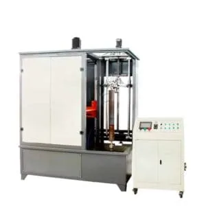
1. Vertical Induction Shaft Hardening Machine
A vertical shaft hardening machine is suitable for long shafts, rods, guide bars, hydraulic rods and cylindrical workpieces that need stable rotation and straight scanning. The workpiece is clamped vertically and the induction coil moves up or down during hardening.
Advantages:
- Suitable for long shafts and rods
- Good workpiece alignment
- Compact floor space
- Easy integration with automatic loading systems
- Stable hardening depth along the shaft length
2. Horizontal Induction Shaft Hardening Machine
A horizontal shaft hardening machine is suitable for short and medium-length shafts, pins, axles, gear shafts and heavy parts. The workpiece is supported horizontally and rotated during heating.
Advantages:
- Convenient loading and unloading
- Suitable for heavy components
- Easy operator access
- Flexible for different workpiece lengths
- Good for batch production
3. CNC Induction Hardening Scanner
A CNC induction hardening scanner uses servo motors, programmable motion control and precise process recipes. It is ideal for factories that require high repeatability, automatic production and strict quality control.
Advantages:
- Programmable hardening length
- Repeatable scanning speed
- Accurate coil positioning
- Recipe storage for different parts
- Easy integration with quality control systems
4. Customized Automatic Shaft Hardening Line
For high-volume production, the system can be customized with automatic loading, unloading, robot handling, cooling tanks, tempering stations, barcode scanning and online monitoring.
Technical Specifications
|
Model |
Power Range |
Frequency Range |
Suitable Diameter |
Suitable Length |
Typical Application |
|---|---|---|---|---|---|
|
HLQ-SH-30 |
30 kW |
30–100 kHz |
10–40 mm |
50–600 mm |
Small pins, short rods |
|
HLQ-SH-60 |
60 kW |
20–80 kHz |
20–80 mm |
100–1000 mm |
Shafts, pins, guide rods |
|
HLQ-SH-100 |
100 kW |
10–60 kHz |
40–120 mm |
200–1500 mm |
Motor shafts, spline shafts |
|
HLQ-SH-160 |
160 kW |
5–50 kHz |
60–180 mm |
300–2500 mm |
Axle shafts, hydraulic rods |
|
HLQ-SH-250 |
250 kW |
1–30 kHz |
100–300 mm |
500–4000 mm |
Heavy-duty shafts |
|
HLQ-SH-Custom |
Customized |
Customized |
Customized |
Customized |
Automatic production lines |
The final machine model should be selected according to workpiece material, diameter, hardening depth, hardened length, production rate and required automation level.
Recommended Model Selection Guide
|
Workpiece Requirement |
Recommended Machine Type |
|---|---|
|
Small pins and short shafts |
High-frequency compact hardening machine |
|
Long guide rods and hydraulic rods |
Vertical CNC shaft hardening machine |
|
Heavy axles and large shafts |
Horizontal medium-frequency hardening machine |
|
Gear shafts and spline shafts |
CNC scanning hardening machine |
|
High-volume automotive parts |
Automatic induction hardening production line |
|
Variable products and small batches |
Flexible semi-automatic hardening system |
Advantages of HLQ Induction Shaft Hardening Machine
1. Fast Heating Speed
Induction heating transfers energy directly into the surface of the metal workpiece. Compared with conventional furnace heating, the heating time is much shorter and the production cycle is greatly reduced.
2. Low Distortion
Only the required surface area is heated, while the core remains relatively cool. This helps reduce overall thermal stress, bending and deformation, especially for long shafts and precision rods.
3. Uniform Hardness Layer
With workpiece rotation, accurate coil design and controlled scanning speed, the machine can produce a uniform hardened layer around the shaft surface.
4. Localized Hardening
The system can harden selected areas such as bearing seats, spline sections, journal surfaces, pin ends or specific wear zones without heating the entire part.
5. Clean and Energy-Efficient Process
Induction hardening does not require open flame or long furnace heating time. It is cleaner, more energy-efficient and easier to integrate into modern workshops.
6. Easy Automation
The machine can be equipped with PLC control, HMI touch screen, servo scanning, automatic quenching, recipe storage and production data management.
7. Better Product Performance
A properly hardened shaft has improved wear resistance, surface hardness, fatigue strength and service life, while maintaining a tough core structure.
Induction Coil and Quenching Design
The induction coil is one of the most important parts of the shaft hardening machine. It determines heating efficiency, hardening width, temperature uniformity and final surface quality.
For shaft and rod hardening, common coil designs include:
- Single-turn ring coil
- Multi-turn spiral coil
- Scanning coil with integrated quench ring
- Split coil for special workpieces
- Profile coil for spline or stepped shafts
- Internal spray quenching coil
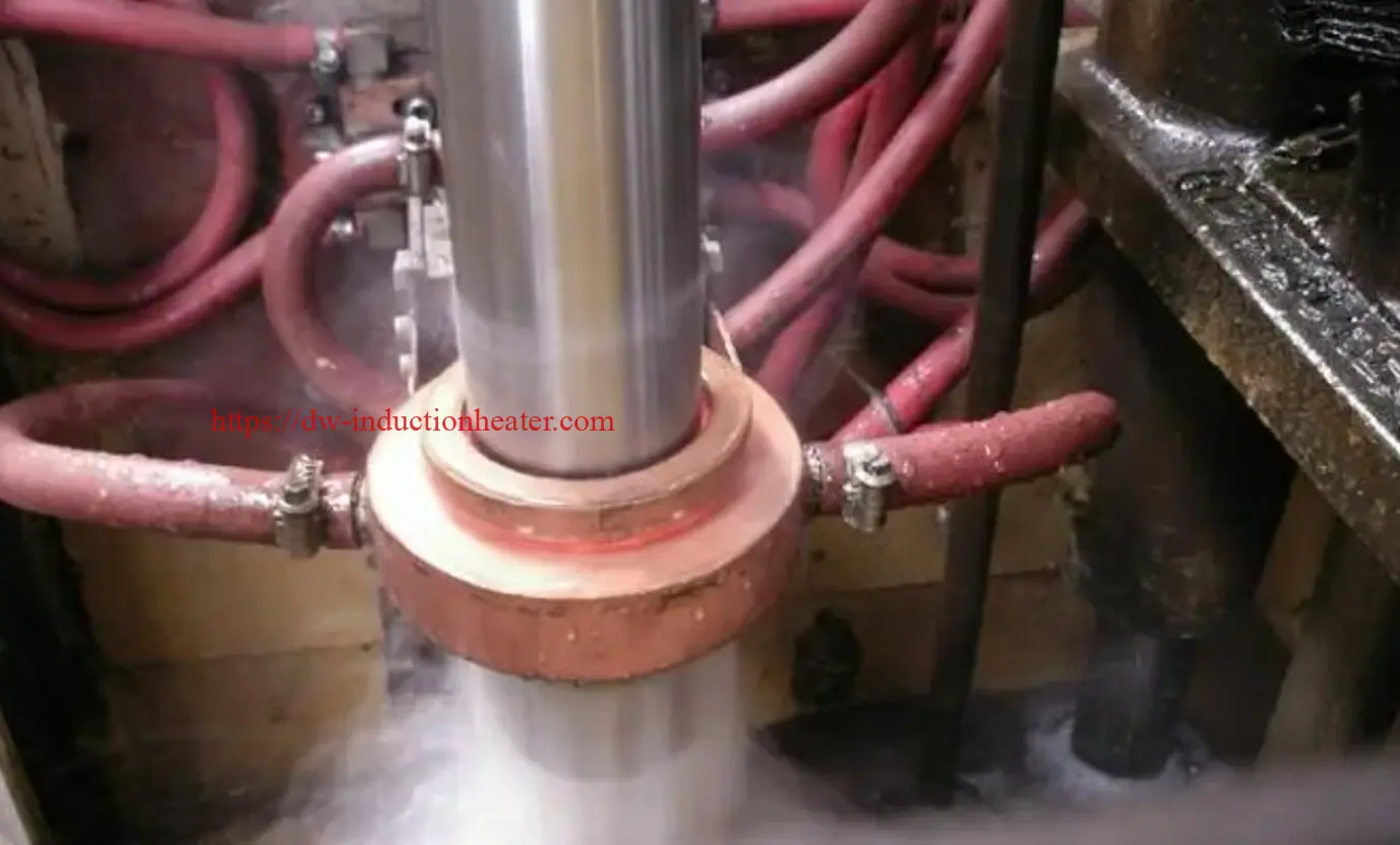
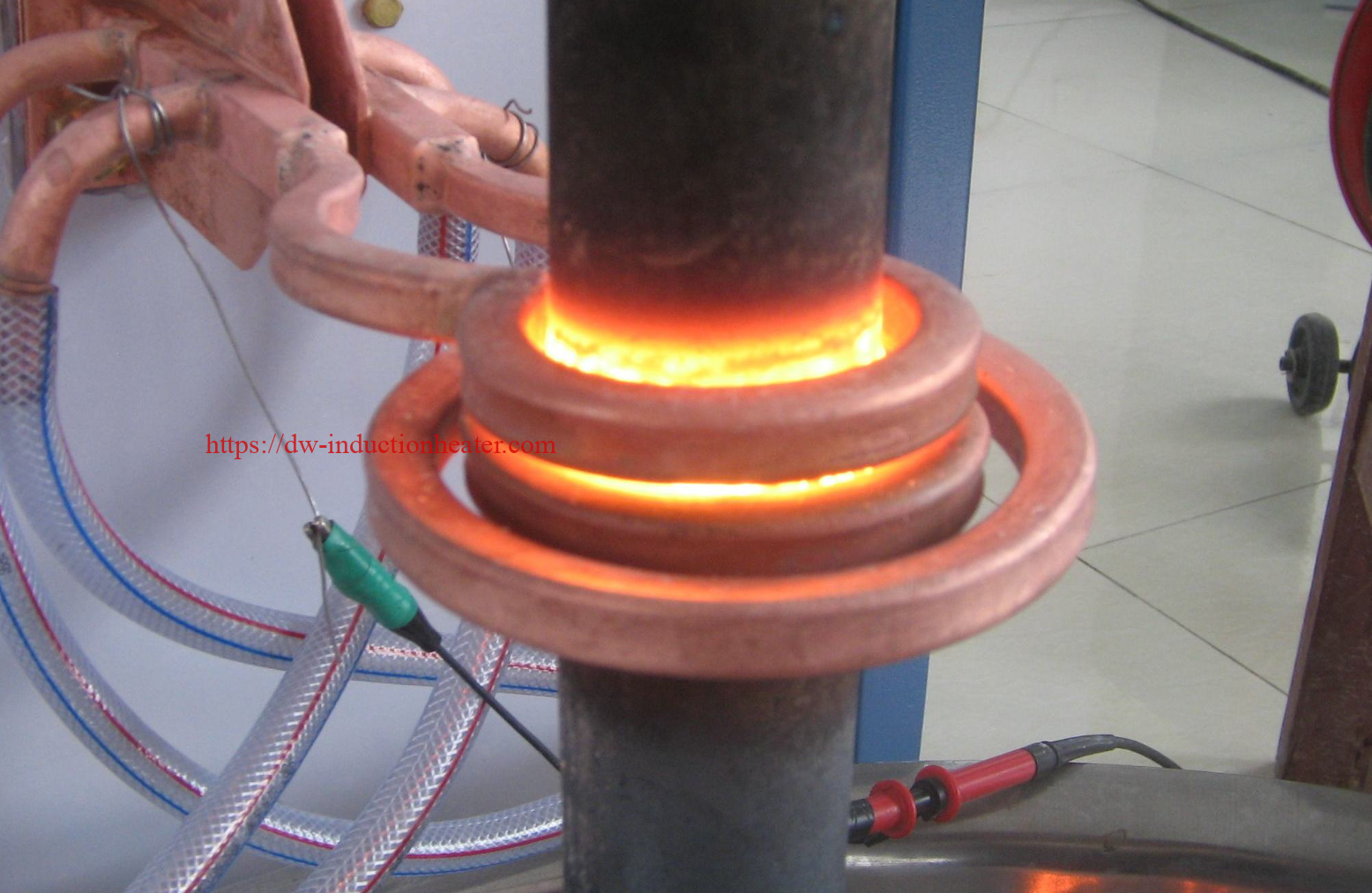 The quenching system can be designed with spray holes located inside the coil or with a separate quench ring following the heating coil. For shaft hardening, inward-facing spray holes are often used to direct the quenching medium toward the shaft surface immediately after heating.
A good coil and quenching design helps achieve:
- Stable hardening depth
- Uniform surface hardness
- Reduced soft bands
- Lower cracking risk
- Better roundness and straightness
- Longer coil service life
Hardening Depth and Frequency Selection
The required hardening depth depends on the shaft size, load condition, material and final application.
|
Required Hardening Depth |
Recommended Frequency Range |
Typical Application |
|---|---|---|
|
0.5–1.5 mm |
50–200 kHz |
Small pins, thin rods, precision parts |
|
1.5–3 mm |
20–80 kHz |
Motor shafts, guide rods, medium shafts |
|
3–5 mm |
5–30 kHz |
Axle shafts, heavy-duty rods |
|
5–8 mm |
1–10 kHz |
Large shafts and heavy components |
Higher frequency is usually suitable for shallow hardening depth, while lower frequency is better for deeper heating penetration. The final selection should be confirmed through material testing and sample hardening trials.
Industries Served
HLQ induction shaft hardening machines are used in many industrial sectors.
|
Industry |
Typical Parts |
|---|---|
|
Automotive |
Axle shafts, drive shafts, transmission shafts, camshafts |
|
Construction machinery |
Pins, bushings, hydraulic rods, pivot shafts |
|
Agricultural machinery |
Gear shafts, PTO shafts, connecting pins |
|
Machine tools |
Guide rods, ball screws, spindle parts |
|
Electric motors |
Rotor shafts, motor shafts |
|
Oil and gas |
Pump shafts, drilling tool parts |
|
Mining machinery |
Heavy pins, rollers, support shafts |
|
Railway |
Axle parts and mechanical transmission components |
|
Hydraulic equipment |
Piston rods and cylinder rods |
|
General machinery |
Wear-resistant cylindrical components |
Case Study: Shaft Surface Hardening for Mechanical Transmission Parts
A machinery parts manufacturer needed to improve the wear resistance of medium-carbon steel transmission shafts. The shafts required a hardened surface layer while maintaining a tough core to resist bending and torque loads.
Workpiece Information
|
Item |
Data |
|---|---|
|
Material |
45 steel / C45 |
|
Workpiece type |
Transmission shaft |
|
Diameter |
45–80 mm |
|
Hardened length |
150–600 mm |
|
Required hardness |
52–58 HRC |
|
Hardening depth |
2–4 mm |
|
Process |
Induction scanning hardening + spray quenching |
Recommended Solution
HLQ recommended a CNC induction shaft hardening machine with adjustable power, servo scanning, workpiece rotation and integrated quenching. The system allowed the customer to store different hardening programs for different shaft models.
Results
|
Result |
Improvement |
|---|---|
|
Surface hardness |
Stable and repeatable |
|
Hardening depth |
Controlled within process requirement |
|
Distortion |
Lower than conventional heat treatment |
|
Production efficiency |
Improved by automatic scanning |
|
Labor requirement |
Reduced through CNC control |
|
Product lifetime |
Increased due to better wear resistance |
Why Choose HLQ?
HLQ Induction Equipment Co., Ltd. provides induction heating, hardening, brazing, forging, melting and heat treatment solutions for industrial manufacturers worldwide. For shaft hardening applications, HLQ can provide not only the induction power supply, but also the complete hardening machine, CNC motion system, induction coil, quenching system, cooling system and process support.
HLQ Can Provide:
- Custom shaft hardening machine design
- Induction power supply selection
- Coil design and manufacturing
- Quenching ring and spray system design
- Vertical and horizontal hardening machines
- CNC scanning systems
- Sample testing support
- Process parameter recommendations
- Installation and operator training
- Complete automatic hardening production lines
How to Choose the Right Induction Shaft Hardening Machine
Before selecting the machine, please prepare the following information:
- Workpiece drawing or photo
- Material grade
- Shaft diameter and length
- Hardened area and hardening length
- Required surface hardness
- Required hardening depth
- Production capacity per hour or per shift
- Current heat treatment process
- Quenching medium requirement
- Automation level requirement
With this information, HLQ engineers can recommend the right power, frequency, coil structure, machine layout and quenching method.
Frequently Asked Questions
1. What is an induction shaft hardening machine used for?
An induction shaft hardening machine is used to harden the surface of shafts, pins, rods, axles, splines and cylindrical steel components. It improves wear resistance, fatigue strength and service life.
2. What parts can be hardened by this machine?
It can harden motor shafts, transmission shafts, hydraulic rods, guide rods, axle shafts, pins, spline shafts, gear shafts, camshafts, crankshafts and other round metal parts.
3. What materials are suitable for induction shaft hardening?
Medium carbon steel and alloy steel are most suitable, such as 1045, C45, 40Cr, 42CrMo, 4140 and similar grades. The material should contain enough carbon to form a hardened surface.
4. What hardening depth can be achieved?
Typical hardening depth ranges from 0.5 mm to 8 mm, depending on material, power, frequency, heating time, scanning speed and quenching conditions.
5. Is vertical or horizontal shaft hardening better?
A vertical machine is often better for long shafts and rods because it provides good alignment and saves floor space. A horizontal machine is suitable for heavy, short or medium-length parts that are easier to load horizontally.
6. Can the machine harden only part of the shaft?
Yes. Induction hardening is ideal for localized hardening. The machine can harden selected areas such as bearing seats, spline sections, journal surfaces or wear zones.
7. Does induction hardening cause distortion?
Induction hardening usually causes less distortion than conventional furnace heat treatment because only the surface or selected area is heated. Proper fixture design, rotation and quenching control are important.
8. What frequency should be used for shaft hardening?
Higher frequency is used for shallow hardening depth, while lower frequency is used for deeper hardening. The suitable frequency depends on shaft diameter and required case depth.
9. Can the machine be automated?
Yes. HLQ can provide manual, semi-automatic and CNC automatic shaft hardening machines with servo scanning, PLC control, recipe storage, automatic quenching and production line integration.
10. How can I get a suitable machine quotation?
Please provide the shaft material, diameter, length, hardening area, required hardness, hardening depth and production capacity. HLQ engineers will recommend a suitable induction power supply, machine structure and coil design.