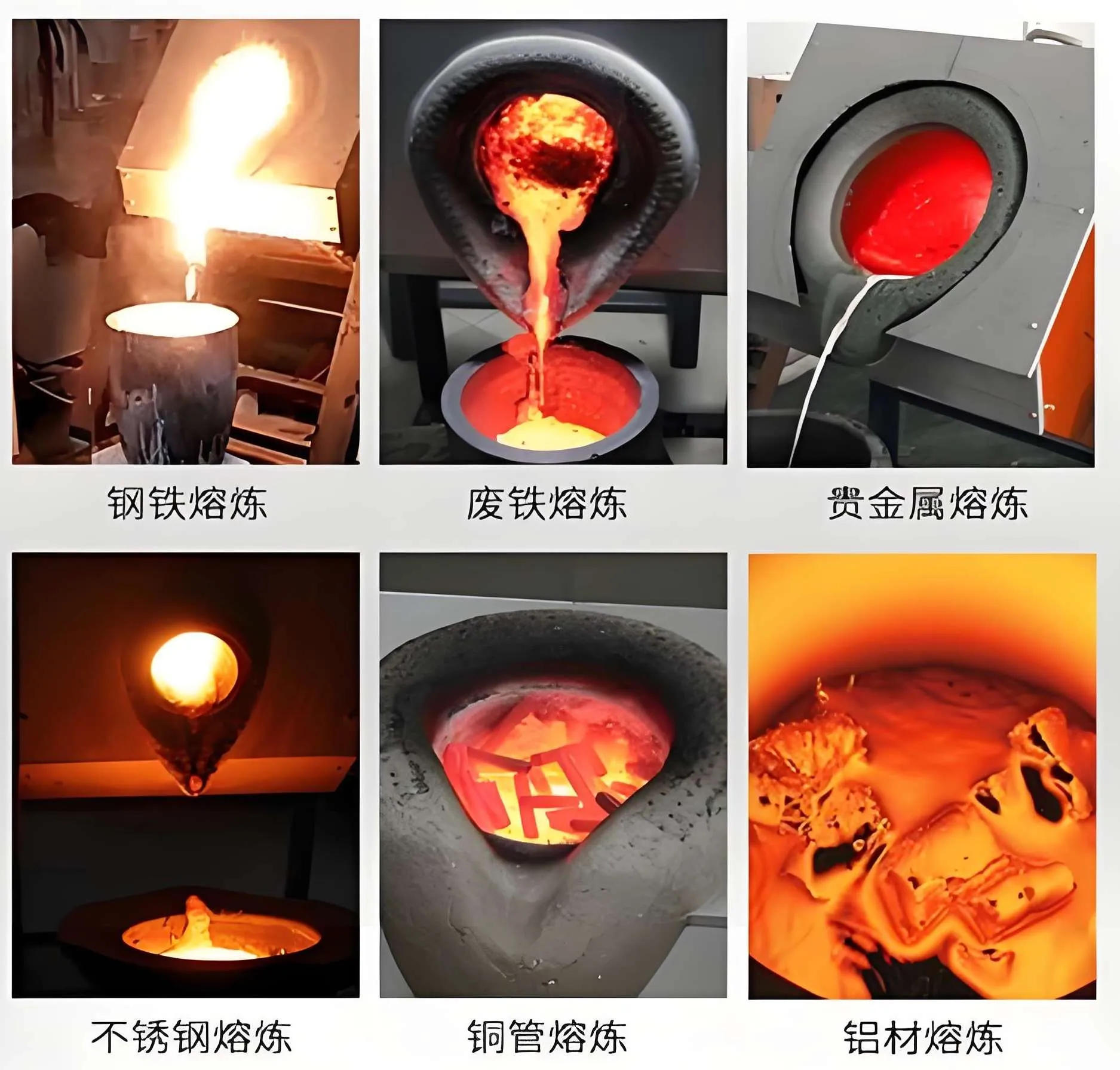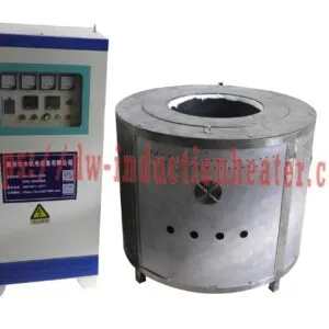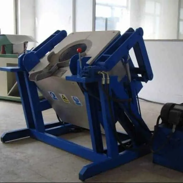


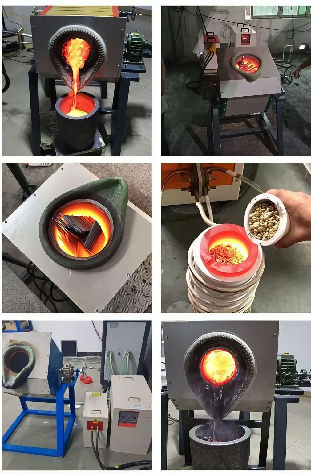



Electric Induction Melting Furnace
Electric Induction Melting Furnace with Electric Tilting Device
The HLQ DW-MF Electric Induction Melting Furnace is designed for controlled batch melting and pouring of steel, stainless steel, copper alloys, aluminum and precious metals. The published product range covers 15–160kW with a medium-frequency operating range of 1–20kHz.
What Is the Electric Induction Melting Furnace?
The HLQ Electric Induction Melting Furnace with Electric Tilting Device
is a medium-frequency batch melting system comprising an induction power generator,
resonant compensation components and a crucible furnace arranged to pour molten
metal by controlled tilting. Instead of heating a crucible with fuel flames,
a water-cooled copper inductor generates an alternating magnetic field that
induces current in conductive metal or a compatible conductive crucible.
The DW-MF series is intended for suitably configured steel, stainless steel,
copper-alloy, aluminum and precious-metal batches. Electrical tilting can
simplify repetitive pouring, but actuator type, braking, tilt limits and
fully loaded performance must be specified separately for the actual supplied unit.
Product Overview
| Parameter | Published Specification | Engineering Notes |
|---|---|---|
| Product Series | DW-MF | Medium-frequency electric melting furnace |
| Models | DW-MF-15 to DW-MF-160 | Eight published models |
| Maximum Listed Input Power | 15–160kW | Actual sustained melting power requires verification |
| Input Supply | Three-phase 380V ±10%, 50/60Hz | Confirm electrical infrastructure |
| Operating Frequency | 1–20kHz | Application and resonant load dependent |
| Tilting Arrangement | Electric Tilting Device | Drive and brake specifications must be confirmed |
| Main Components | MF Generator, Tilting Furnace, Compensation Capacitor | Verify full scope of supply |
For additional furnace configurations, compare HLQ’s
induction melting furnaces with tilting devices.
Key Applications
Electric induction melting furnaces are suitable for controlled batch
melting operations in foundries, casting workshops, metal recycling facilities
and specialized alloy production.
| Application | Typical Material | Production Objective | Critical Consideration |
|---|---|---|---|
| Steel Casting | Carbon Steel | Controlled melting and pouring | High-temperature refractory compatibility |
| Stainless Steel Casting | 304, 316 and Other Stainless Grades | Alloy melting | Temperature and composition control |
| Copper Casting | Copper and Copper Alloys | Nonferrous metal melting | Oxidation and crucible compatibility |
| Brass and Bronze Casting | Brass, Bronze | Precision alloy casting | Alloy composition and fume extraction |
| Aluminum Recycling | Aluminum Ingots and Clean Scrap | Metal recovery | Moisture, dross and contamination |
| Jewelry Manufacturing | Gold and Silver | Precious-metal casting | Purity and metal recovery |
| Laboratory Alloy Development | Specialty Alloys | Experimental batch melting | Traceability and process repeatability |
 Electric Tilting vs. Hydraulic Tilting
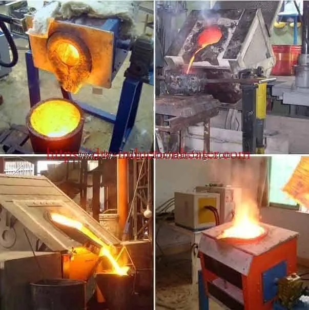 Electric Tilting vs. Hydraulic Tilting
| Comparison | Electric Tilting | Hydraulic Tilting |
|---|---|---|
| Typical Use | Small and Medium Batch Applications | Larger and Heavier Furnace Applications |
| Drive System | Electric Actuator, Configuration Dependent | Hydraulic Cylinder and Power Unit |
| Primary Design Requirement | Motor Torque and Braking | Hydraulic Force and Pressure Control |
| Safety | Travel Stops and Safe Holding | Pressure Protection and Safe Holding |
| Final Selection | Based on Actual Furnace Load | Based on Actual Furnace Load |
Suitable Materials
Material properties determine the required melting temperature,
heating energy, crucible selection and operating conditions.
| Material | Reference Melting Temperature | Engineering Consideration |
|---|---|---|
| Carbon Steel | Approximately 1425–1540°C | Depends on carbon and alloy content |
| Stainless Steel | Approximately 1370–1530°C | Grade-dependent melting range |
| Cast Iron | Composition Dependent | Carbon and silicon influence melting behavior |
| Copper | 1085°C | High electrical conductivity |
| Brass | Alloy Dependent | Zinc evaporation and fume control |
| Aluminum | 660°C for Pure Aluminum | Alloy temperature and oxidation control |
| Gold | 1064°C | Purity and crucible contamination |
| Silver | 962°C | Temperature and metal recovery |
Crucible Selection Guide
| Crucible Type | Possible Application | Engineering Requirement |
|---|---|---|
| Graphite-Based | Compatible Nonferrous Applications | Check alloy compatibility and oxidation |
| Ceramic | Selected Metal Melting Applications | Verify chemical compatibility and coupling |
| Refractory Lining | Steel and Cast Iron Melting | High-temperature and slag resistance |
| Dedicated Precious-Metal Crucible | Gold and Silver | Minimize contamination and metal losses |
For larger copper melting applications, explore
copper induction melting furnace designs.
Working Principle
The electric induction melting furnace uses electromagnetic induction
to generate heat in conductive metal.
The induction generator supplies medium-frequency alternating current
to a water-cooled copper coil. The resulting alternating magnetic field
induces eddy currents in the charge or a compatible conductive crucible.
Electrical resistance converts these currents into heat.
When the metal reaches the required temperature and composition,
the electric tilting device allows controlled pouring into a suitable
ladle or mold.
Figure 1. Working Principle Diagram
      THREE-PHASE AC INPUT
               |
               v
    +----------------------+
    | DW-MF GENERATOR      |
    +----------------------+
               |
               v
    +----------------------+
    | CAPACITOR / MATCHING |
    +----------------------+
               |
               v
    +----------------------+
    | INDUCTION COIL       |
    | WATER COOLED         |
    +----------------------+
               |
               v
     ALTERNATING MAGNETIC
             FIELD
               |
               v
    +----------------------+
    | METAL + CRUCIBLE     |
    | EDDY CURRENT HEATING |
    +----------------------+
               |
               v
       MELTING COMPLETED
               |
               v
       TEMPERATURE CHECK
               |
               v
       ELECTRIC TILTING
               |
               v
        CONTROLLED POUR

Operating Stages
| Stage | Physical Process | Monitoring Requirement |
|---|---|---|
| Initial Heating | Charge absorbs induction energy | Electrical input and cooling |
| Partial Melting | Molten pool begins forming | Load matching and power stability |
| Complete Melting | Metal becomes liquid | Temperature and slag |
| Superheating | Temperature rises toward tapping setpoint | Temperature measurement |
| Electric Tilting | Furnace rotates for pouring | Drive, brake and pouring safety |
Technical Specifications
The following specifications are based on the published DW-MF series
information. Where the original product page does not provide a verified
parameter, confirmation is required before final equipment selection.
| Parameter | Specification | Notes |
|---|---|---|
| Product Name | Electric Induction Melting Furnace | With Electric Tilting Device |
| Series | DW-MF | Medium-Frequency Equipment |
| Maximum Listed Input Power | 15–160kW | Model Dependent |
| Power Supply | 380V ±10%, Three-Phase, 50/60Hz | Published Line Supply |
| Operating Frequency | 1–20kHz | Application Dependent |
| Additional Voltage Entry | 70–550V | Meaning Requires Manufacturer Clarification |
| Duty Cycle | 100% / 24 Hours Claimed | Requires Rated Cooling Conditions |
| Electric Tilting Mechanism | Specified by Product Name | Detailed Drive Structure Not Published |
| Cooling System | Water Cooling Required | Flow and Pressure Must Be Confirmed |
| Main Components | MF Generator, Furnace and Compensation Capacitor | Confirm Complete Supply Scope |
DW-MF Power Comparison
| Model | Maximum Input Power | Published Weight | Electrical Supply |
|---|---|---|---|
| DW-MF-15 | 15kW | 50kg | 380V Three-Phase |
| DW-MF-25 | 25kW | 50kg | 380V Three-Phase |
| DW-MF-35 | 35kW | 65kg | 380V Three-Phase |
| DW-MF-45 | 45kW | 70kg | 380V Three-Phase |
| DW-MF-70 | 70kW | 80kg | 380V Three-Phase |
| DW-MF-90 | 90kW | 94kg | 380V Three-Phase |
| DW-MF-110 | 110kW | 114kg | 380V Three-Phase |
| DW-MF-160 | 160kW | 145kg | 380V Three-Phase |
The original source does not clearly establish whether the listed weights
refer to the generator cabinets or complete furnace assemblies.
Published Melting Capacity
| Model | Steel / Stainless Steel | Gold / Silver | Aluminum |
|---|---|---|---|
| DW-MF-15 | Not Published | 5 or 10kg | 3kg |
| DW-MF-25 | 4 or 8kg | 10 or 20kg | 6kg |
| DW-MF-35 | 10 or 14kg | 20 or 30kg | 12kg |
| DW-MF-45 | 18 or 22kg | 40 or 50kg | 21kg |
| DW-MF-70 | 28kg | 60 or 80kg | 30kg |
| DW-MF-90 | 50kg | 80 or 100kg | 40kg |
| DW-MF-110 | 75kg | 100 or 150kg | 50kg |
| DW-MF-160 | 100kg | 150 or 250kg | 75kg |
These figures are published batch-capacity references, not guaranteed
hourly melting production. Alternative quantities may require different
crucibles or furnace configurations.
Recommended Model Selection
An induction melting furnace should be selected according to the actual
metal charge, crucible capacity, target temperature and production cycle.
| Application | Material | Recommended Power | Frequency |
|---|---|---|---|
| Small Jewelry Casting | Gold / Silver | 15kW DW-MF-15 | Load-Matched Within Published Series |
| Small Steel Melting | Steel / Stainless Steel | 25kW DW-MF-25 | Confirm Operating Frequency |
| Aluminum Casting | Aluminum | 35kW DW-MF-35 | Crucible and Coil Dependent |
| Small Foundry Melting | Steel | 45kW DW-MF-45 | Verify Resonant Matching |
| Medium Nonferrous Melting | Aluminum | 70kW DW-MF-70 | Load-Matched |
| 50kg Steel Batch | Steel | 90kW DW-MF-90 | Verify Actual Frequency |
| 75kg Steel Batch | Steel | 110kW DW-MF-110 | Confirm Under Full Load |
| 100kg Steel Batch | Steel | 160kW DW-MF-160 | Factory Qualification Required |
Additional Selection Criteria
| Selection Factor | Required Information | Engineering Purpose |
|---|---|---|
| Material Grade | Metal Composition | Determines Crucible and Temperature |
| Batch Weight | kg per Melt | Determines Furnace Capacity |
| Production Rate | kg/h or Batches/Shift | Determines Real Productivity |
| Pouring Requirement | Ladle Position and Height | Determines Tilting Geometry |
| Electrical Supply | Voltage, Frequency and Transformer Capacity | Determines Electrical Compatibility |
| Cooling | Water Flow, Temperature and Pressure | Protects Electrical Components |
Process Workflow
  CHECK METAL GRADE
          |
          v
  INSPECT CHARGE DRYNESS
          |
          v
  CHECK CRUCIBLE AND COOLING
          |
          v
  LOAD METAL CHARGE
          |
          v
  START INDUCTION MELTING
          |
          v
  CHECK TEMPERATURE AND CHEMISTRY
          |
          v
  PREPARE DRY LADLE
          |
          v
  ACTIVATE ELECTRIC TILTING
          |
          v
  POUR MOLTEN METAL
          |
          v
  RETURN FURNACE TO HOME POSITION
          |
          v
  RECORD ENERGY AND PRODUCTION

Process Inspection Requirements
| Process Stage | Inspection | Acceptance Requirement |
|---|---|---|
| Charge Preparation | Material and Dryness | Approved Dry Charge |
| Cooling Check | Flow and Pressure | Within Equipment Limits |
| Heating | Electrical Power and Frequency | Stable Operation |
| Melting | Temperature and Chemistry | Within Casting Specification |
| Tilting | Drive and Pouring Path | Controlled Movement |
| Production Recording | Charge, Energy and Time | Complete Batch Record |
Coil and Fixture Design
The induction coil, crucible and electric tilting system must be
designed as an integrated electromagnetic and mechanical assembly.
Design Parameters
| Component | Design Requirement | Potential Failure |
|---|---|---|
| Copper Induction Coil | Correct Turns, Conductor Size and Cooling | Overheating or Electrical Short |
| Compensation Capacitor | Suitable Resonant Matching | Unstable Power |
| Crucible | Metal-Compatible Material | Cracking or Contamination |
| Furnace Frame | Rated Mechanical Strength | Uncontrolled Movement |
| Electric Tilting Drive | Correct Torque and Speed | Uncontrolled Pouring |
| Tilting Brake | Safe Holding Under Rated Load | Unexpected Movement |
| Water Hoses | Adequate Flexible Routing | Leakage or Fatigue |
| Pouring Spout | Suitable Ladle Alignment | Metal Spillage |
Electric Tilting Mechanism Inspection
| Inspection Item | Required Verification |
|---|---|
| Motor / Actuator | Rated Load and Torque |
| Gearbox | Actual Drive Configuration |
| Brake | Safe Holding During Power Loss |
| Travel Limits | Approved Maximum Tilt Angle |
| Emergency Stop | Safe Equipment Response |
| Loaded Test | Controlled Movement at Rated Furnace Load |
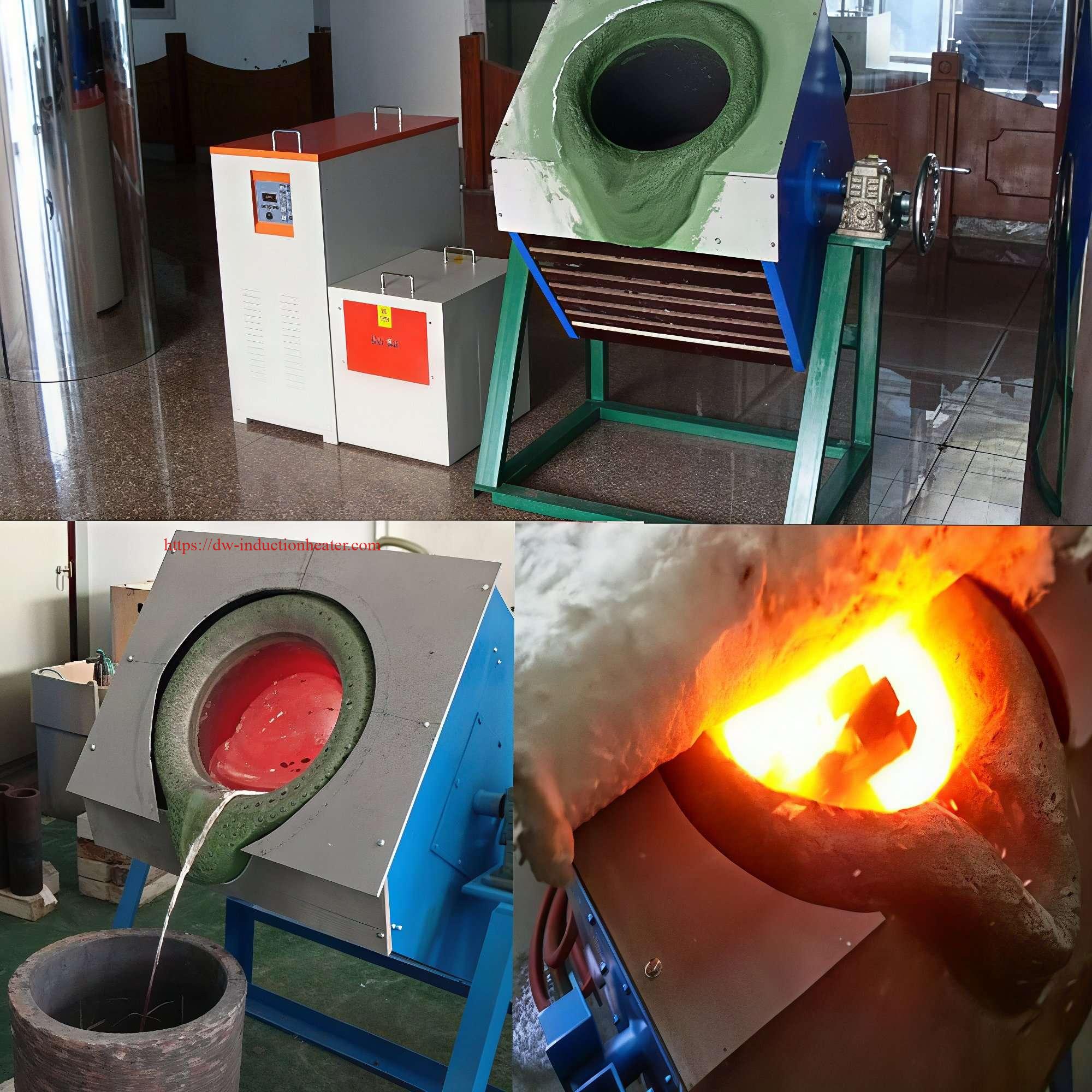
Cooling Water Calculation
For water near ordinary industrial temperatures:
Cooling Load (kW) = 1.163 × Flow (m³/h) × Temperature Rise (°C)
| Water Flow | Temperature Rise | Heat Removed |
|---|---|---|
| 3m³/h | 5°C | 17.4kW |
| 5m³/h | 5°C | 29.1kW |
| 8m³/h | 5°C | 46.5kW |
| 10m³/h | 5°C | 58.2kW |
These are illustrative calculations, not confirmed DW-MF cooling
requirements. The actual cooling system should be selected from
measured heat rejection and manufacturer-specified water conditions.
For related generator configurations, see HLQ’s
medium-frequency induction heating power supply systems.
Control System and Automation
The original page does not specify a complete PLC control architecture,
tilting-drive interface or automatic pouring system.
The following functions are recommended engineering features that
should be confirmed for the selected model.
| Control Function | Purpose | Required Verification |
|---|---|---|
| Power Regulation | Control Heating Power | Actual Regulation Range |
| Frequency Monitoring | Confirm Resonance | Measured Operating Frequency |
| Temperature Measurement | Control Melting Temperature | Sensor Accuracy |
| Water Flow Protection | Protect Coil and Generator | Flow Interlock Testing |
| Electric Tilting Control | Control Furnace Movement | Loaded Tilt Test |
| Emergency Stop | Prevent Unsafe Operation | Safe Stop Procedure |
| PLC / HMI | Process Monitoring | Optional Configuration |
| Data Logging | Production Traceability | Quote-Specific Integration |
Recommended Production KPIs
| Parameter | Unit | Purpose |
|---|---|---|
| Real Input Power | kW | Actual Electrical Load |
| Electrical Consumption | kWh | Batch Energy Cost |
| Operating Frequency | kHz | Load Matching |
| Metal Temperature | °C | Melting Quality |
| Batch Weight | kg | Productivity Calculation |
| Tap-to-Tap Time | min | Actual Production Capacity |
| Cooling Water Flow | m³/h | Equipment Protection |
Common Problems and Solutions
| Problem | Possible Cause | Recommended Solution |
|---|---|---|
| Melting Time Too Long | Low Average Power or Excessive Heat Loss | Measure Actual kW and kWh |
| Unstable Electrical Power | Resonant Mismatch | Inspect Coil and Capacitor Matching |
| Coil Overheating | Insufficient Cooling | Check Water Flow and Connections |
| Crucible Cracking | Thermal Shock or Material Incompatibility | Follow Approved Crucible Procedures |
| Excessive Oxidation | High Temperature or Long Holding Time | Optimize Melting Temperature |
| Inverter Trips | Electrical Fault or Load Mismatch | Use Approved Diagnostic Procedure |
| Unstable Electric Tilting | Drive or Mechanical Fault | Inspect Actuator and Brake |
| Incorrect Pouring Direction | Improper Ladle Alignment | Review Pouring Geometry |
| Water Leakage | Damaged Cooling Components | Follow Emergency Safety Procedure |
| High Metal Loss | Oxidation, Slag or Spillage | Improve Charge Preparation and Pouring |
Engineering Selection Guide
1. Calculate Electrical Energy Required for Melting
The electrical energy required for batch melting depends on the
material, initial temperature, melting point, superheat and
overall system losses.
Electrical Energy (kWh) = Charge Weight (tonnes) × Specific Consumption (kWh/t)
Illustrative Melting Energy Planning
| Material | Illustrative Electricity Consumption | Engineering Notes |
|---|---|---|
| Steel | 650–950kWh/t | Depends on Furnace Conditions |
| Aluminum | 350–550kWh/t | Depends on Scrap and Dross Losses |
| Copper Alloys | 350–600kWh/t | Depends on Crucible and Charge |
| Gold / Silver | Model-Specific Measurement Required | Small Batch Losses Can Be Significant |
These values are preliminary planning assumptions and are not
independently verified DW-MF performance data.
2. Estimate Melting Time
Estimated Energized Time (min) =
60 × Electrical Energy (kWh) / Average Real Input Power (kW)
| Illustrative Scenario | Energy Required | Assumed Average Power | Estimated Time |
|---|---|---|---|
| 8kg Steel | 6.4kWh | 20kW | 19.2min |
| 22kg Steel | 17.6kWh | 35kW | 30.2min |
| 50kg Steel | 40kWh | 75kW | 32min |
| 75kg Aluminum | 33.75kWh | 120kW | 16.9min |
| 100kg Steel | 80kWh | 120kW | 40min |
The table is based on hypothetical energy consumption and average
electrical input. It does not represent tested heating times or
guaranteed production output.
Figure 3. Melting Time vs. Average Electrical Power
ASSUMED 100kg STEEL BATCH
TOTAL ELECTRICAL ENERGY: 80kWh

AVERAGE POWER       ENERGIZED TIME

80kW    ########################   60min

100kW   ###################        48min

120kW   ################           40min

160kW   ############               30min

Illustrative calculation only.
3. Calculate Actual Production Capacity
Gross Production (kg/h) =
60 × Batch Weight (kg) / Tap-to-Tap Time (min)
| Batch Weight | Tap-to-Tap Time | Gross Production |
|---|---|---|
| 10kg | 25min | 24kg/h |
| 25kg | 40min | 37.5kg/h |
| 50kg | 45min | 66.7kg/h |
| 75kg | 50min | 90kg/h |
| 100kg | 60min | 100kg/h |
Actual saleable production also depends on metal yield,
slag losses, casting acceptance and equipment downtime.
4. Calculate Three-Phase Electrical Requirements
For balanced three-phase electrical supply:
Apparent Power (kVA) = 1.732 × Voltage (V) × Current (A) / 1000
Real Power (kW) = Apparent Power (kVA) × Power Factor
| Assumed Input Power | Assumed Power Factor | Calculated Apparent Power | Approximate Current at 380V |
|---|---|---|---|
| 25kW | 0.90 | 27.8kVA | 42A |
| 45kW | 0.90 | 50kVA | 76A |
| 90kW | 0.90 | 100kVA | 152A |
| 160kW | 0.90 | 177.8kVA | 270A |
These calculations assume a power factor of 0.90.
The actual electrical design should use measured or certified
equipment data, including harmonic and transformer requirements.
5. Electric Tilting System Selection
| Design Parameter | Engineering Requirement |
|---|---|
| Furnace Weight | Include Furnace Body, Crucible and Molten Metal |
| Center of Gravity | Evaluate Changes During Tilting |
| Tilting Speed | Controlled Pouring Requirement |
| Brake | Safe Holding Under Full Load |
| Travel Limits | Prevent Mechanical Overtravel |
| Power Failure | Documented Safe Response |
| Cooling Connections | Flexible Routing During Movement |
6. Factory Acceptance Testing
| Acceptance Test | Required Measurement |
|---|---|
| Equipment Identification | Model, Nameplate and Technical Drawings |
| Electrical Performance | Actual kW, kWh, Current and Frequency |
| Melting Test | Metal, Charge Weight and Temperature |
| Production Capacity | Complete Tap-to-Tap Time |
| Electric Tilting | Loaded Movement, Brake and Travel Limits |
| Cooling System | Water Flow, Pressure and Temperature |
| Safety | Emergency Stop and Interlock Testing |

Advantages
| Advantage | Industrial Benefit | Qualification |
|---|---|---|
| Induction Heating | Electrical Heating of Conductive Metal | Efficiency Depends on Coupling |
| Electric Tilting | Controlled Pouring Operation | Requires Safe Drive Design |
| Power Control | Adjustable Melting Process | Actual Control Range Must Be Verified |
| Multiple Models | 15–160kW Range | Material-Specific Capacity |
| Batch Production | Suitable for Small Foundries | Actual Throughput Must Be Tested |
| Process Monitoring | Energy and Production Records | Requires Suitable Instruments |
Limitations
| Limitation | Engineering Impact | Recommended Action |
|---|---|---|
| Generalized Melting Time | Not Verified for Every Model | Perform Factory Melting Tests |
| Ambiguous Voltage Parameter | Potential Electrical Design Error | Confirm Meaning of 70–550V |
| Unspecified Tilting Drive | Cannot Confirm Torque and Safety | Request Mechanical Drawings |
| Different Crucible Requirements | Possible Contamination or Damage | Use Metal-Compatible Crucibles |
| Cooling Water Dependence | Risk of Overheating | Provide Reliable Cooling Interlocks |
| Molten Metal Hazards | Risk of Splashing and Water-Contact Explosions | Apply Approved Safety Procedures |
| Reactive Alloy Limitations | Special Atmosphere May Be Required | Use Purpose-Designed Equipment |
Why Choose HLQ Induction Equipment?
HLQ Induction Equipment Co., Ltd. supplies medium-frequency induction
heating generators and metal melting equipment for industrial applications.
For an electric tilting furnace project, the correct solution must
combine suitable electrical power, a matched induction coil, a compatible
crucible, reliable cooling and a properly designed tilting mechanism.
Customers should request complete technical specifications and
factory acceptance results based on their actual metal and required
production capacity.
Information Required for Quotation
| Customer Requirement | Information to Provide |
|---|---|
| Material | Metal Grade and Composition |
| Batch Capacity | kg per Melt |
| Production | kg/h or Batches per Shift |
| Temperature | Initial and Tapping Temperature |
| Electricity | Voltage, Frequency and Transformer Capacity |
| Cooling | Water Temperature, Flow and Pressure |
| Electric Tilting | Ladle Height, Pouring Position and Drive Requirements |
| Acceptance Test | Melting Time, kWh/t and Loaded Tilting Test |
For larger ferrous foundries, explore HLQ
industrial induction furnaces for steel and cast iron melting.
For precious-metal applications, compare
induction gold melting furnace systems.
Core FAQs
FAQ 1. What is an electric induction melting furnace?
An electric induction melting furnace is a system that melts conductive
metal using electromagnetic induction. Alternating current in an induction
coil creates a magnetic field that induces electrical currents and
heat within the charge or a suitable conductive crucible.
FAQ 2. What is the purpose of an electric tilting device?
The electric tilting device moves the furnace into a controlled pouring
position. Its mechanical design must provide adequate load capacity,
travel limits, braking and safe handling of molten metal.
FAQ 3. Which DW-MF models are available?
The published DW-MF series includes eight models:
DW-MF-15, DW-MF-25, DW-MF-35, DW-MF-45, DW-MF-70,
DW-MF-90, DW-MF-110 and DW-MF-160.
Their maximum listed input powers range from 15kW to 160kW.
FAQ 4. How much steel can DW-MF-160 melt?
The published capacity table lists 100kg of steel or stainless steel
for the DW-MF-160 configuration. This is a batch-capacity reference
rather than a guaranteed hourly melting rate.
FAQ 5. How long does one batch take to melt?
The original product page describes approximately 30–50 minutes for
an initial cold furnace and 20–30 minutes for subsequent hot-furnace
melts. The actual time depends on charge mass, material, crucible,
temperature and sustained electrical power.
FAQ 6. What cooling system is required?
The cooling system must provide adequate water flow, pressure and
temperature control for the generator, induction coil and other
water-cooled components. Cooling equipment should be selected from
the actual heat load and manufacturer’s requirements.
FAQ 7. Can one electric induction furnace melt different metals?
Different metals may be melted using suitably configured induction
furnaces, but the same crucible, lining and process settings should
not automatically be used for all alloys.
Material compatibility and operating temperature must be verified.
FAQ 8. How should an electric induction melting furnace be selected?
Select the furnace according to the metal grade, batch weight,
target melting temperature, production rate, available electricity,
cooling conditions and pouring requirements.
The final selection should be validated through a factory acceptance
test using representative material.