Induction Hardening of Large-Diameter Shafts and Cylinders
Introduction
A. Definition of induction hardening
Induction hardening is a heat treatment process that selectively hardens the surface of metallic components using electromagnetic induction. It is widely employed in various industries to enhance the wear resistance, fatigue strength, and durability of critical components.
B. Importance for large-diameter components
Large-diameter shafts and cylinders are essential components in numerous applications, ranging from automotive and industrial machinery to hydraulic and pneumatic systems. These components are subjected to high stresses and wear during operation, necessitating a robust and durable surface. Induction hardening plays a crucial role in achieving the desired surface properties while maintaining the ductility and toughness of the core material.
II. Principles of Induction Hardening
A. Heating mechanism
1. Electromagnetic induction
The induction hardening process relies on the principle of electromagnetic induction. An alternating current flows through a copper coil, creating a rapidly alternating magnetic field. When a electrically conductive workpiece is placed within this magnetic field, eddy currents are induced within the material, causing it to heat up.
2. Skin effect
The skin effect is a phenomenon where the induced eddy currents are concentrated near the surface of the workpiece. This results in rapid heating of the surface layer while minimizing heat transfer to the core. The depth of the hardened case can be controlled by adjusting the induction frequency and power levels.
B. Heating pattern
1. Concentric rings
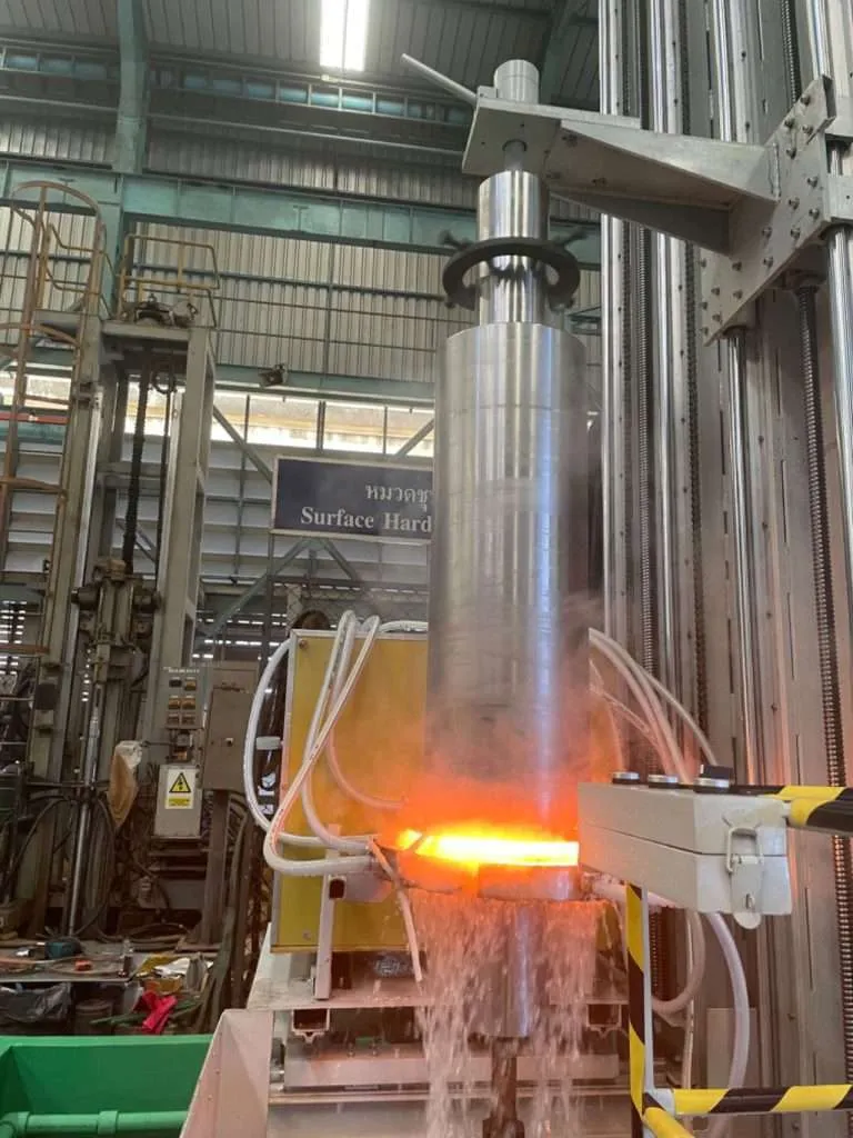
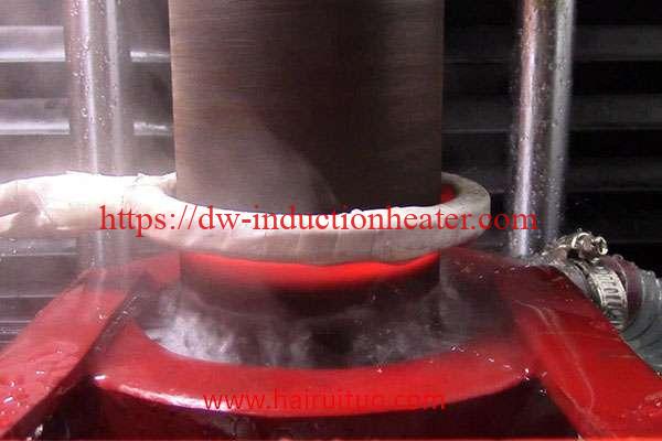
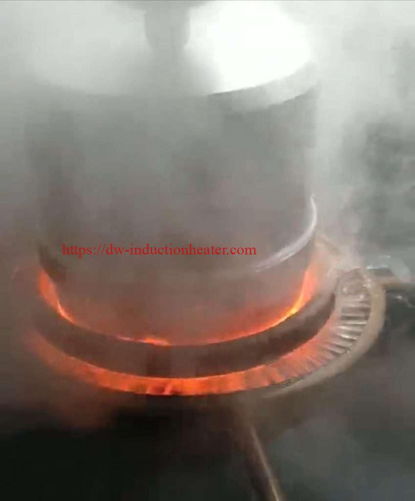
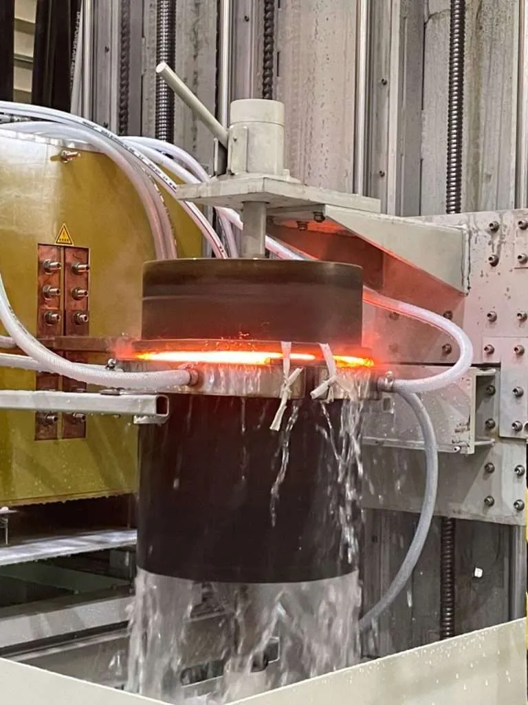
During induction hardening of large-diameter components, the heating pattern typically forms concentric rings on the surface. This is due to the distribution of the magnetic field and the resulting eddy current patterns.
2. End effects
At the ends of the workpiece, the magnetic field lines tend to diverge, leading to a non-uniform heating pattern known as the end effect. This phenomenon requires specific strategies to ensure consistent hardening throughout the component.
III. Advantages of Induction Hardening
A. Selective hardening
One of the primary advantages of induction hardening is its ability to selectively harden specific areas of a component. This allows for the optimization of wear resistance and fatigue strength in critical regions while maintaining ductility and toughness in non-critical areas.
B. Minimal distortion
Compared to other heat treatment processes, induction hardening results in minimal distortion of the workpiece. This is because only the surface layer is heated, while the core remains relatively cool, minimizing thermal stresses and deformation.
C. Improved wear resistance
The hardened surface layer achieved through induction hardening significantly enhances the wear resistance of the component. This is particularly important for large-diameter shafts and cylinders that are subjected to high loads and friction during operation.
D. Increased fatigue strength
The compressive residual stresses induced by the rapid cooling during the induction hardening process can improve the fatigue strength of the component. This is crucial for applications where cyclic loading is a concern, such as in automotive and industrial machinery.
IV. Induction Hardening Process
A. Equipment
1. Induction heating system
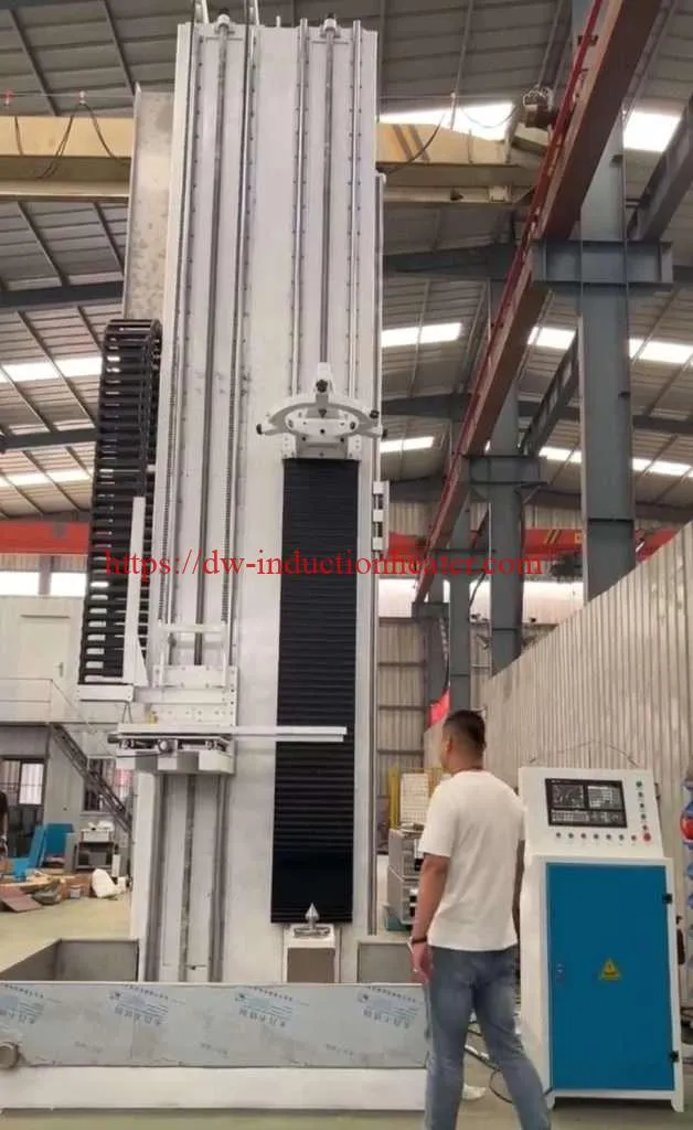
The induction heating system consists of a power supply, a high-frequency inverter, and an induction coil. The power supply provides the electrical energy, while the inverter converts it to the desired frequency. The induction coil, typically made of copper, generates the magnetic field that induces eddy currents in the workpiece.
2. Quenching system
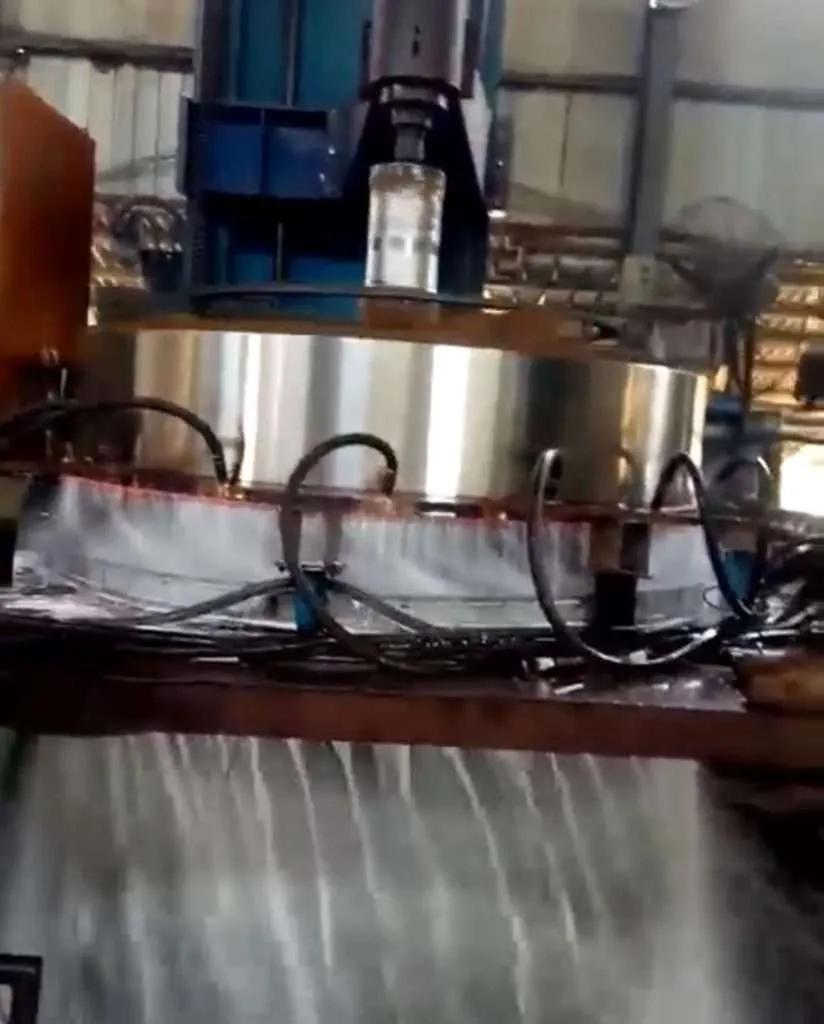
After the surface layer is heated to the desired temperature, rapid cooling (quenching) is necessary to achieve the desired microstructure and hardness. Quenching systems can utilize various media, such as water, polymer solutions, or gas (air or nitrogen), depending on the component’s size and geometry.
B. Process parameters
1. Power
The power level of the induction heating system determines the rate of heating and the depth of the hardened case. Higher power levels result in faster heating rates and deeper case depths, while lower power levels provide better control and minimize potential distortion.
2. Frequency
The frequency of the alternating current in the induction coil influences the depth of the hardened case. Higher frequencies result in shallower case depths due to the skin effect, while lower frequencies penetrate deeper into the material.
3. Heating time
The heating time is crucial for achieving the desired temperature and microstructure in the surface layer. Precise control of the heating time is essential to prevent overheating or underheating, which can lead to undesirable properties or distortion.
4. Quenching method
The quenching method plays a vital role in determining the final microstructure and properties of the hardened surface. Factors such as quenching medium, flow rate, and uniformity of coverage must be carefully controlled to ensure consistent hardening throughout the component.
V. Challenges with Large-Diameter Components
A. Temperature control
Achieving uniform temperature distribution across the surface of large-diameter components can be challenging. Temperature gradients can lead to inconsistent hardening and potential distortion or cracking.
B. Distortion management
Large-diameter components are more susceptible to distortion due to their size and the thermal stresses induced during the induction hardening process. Proper fixturing and process control are essential to minimize distortion.
C. Quenching uniformity
Ensuring uniform quenching across the entire surface of large-diameter components is crucial for achieving consistent hardening. Inadequate quenching can result in soft spots or uneven hardness distribution.
VI. Strategies for Successful Hardening
A. Heating pattern optimization
Optimizing the heating pattern is essential for achieving uniform hardening on large-diameter components. This can be accomplished through careful coil design, adjustments to the induction frequency and power levels, and the use of specialized scanning techniques.
B. Induction coil design
The design of the induction coil plays a crucial role in controlling the heating pattern and ensuring uniform hardening. Factors such as coil geometry, turn density, and positioning relative to the workpiece must be carefully considered.
C. Quenching system selection
Selecting the appropriate quenching system is vital for successful hardening of large-diameter components. Factors such as quenching medium, flow rate, and coverage area must be evaluated based on the component’s size, geometry, and material properties.
D. Process monitoring and control
Implementing robust process monitoring and control systems is essential for achieving consistent and repeatable results. Temperature sensors, hardness testing, and closed-loop feedback systems can help maintain process parameters within acceptable ranges.
VII. Applications
A. Shafts
1. Automotive
Induction hardening is widely used in the automotive industry for hardening large-diameter shafts in applications such as driveshafts, axles, and transmission components. These components require high wear resistance and fatigue strength to withstand the demanding operating conditions.
2. Industrial machinery
Large-diameter shafts are also commonly hardened using induction hardening in various industrial machinery applications, such as power transmission systems, rolling mills, and mining equipment. The hardened surface ensures reliable performance and extended service life under heavy loads and harsh environments.
B. Cylinders
1. Hydraulic
Hydraulic cylinders, particularly those with large diameters, benefit from induction hardening to improve wear resistance and extend service life. The hardened surface minimizes wear caused by high-pressure fluid and sliding contact with seals and pistons.
2. Pneumatic
Similar to hydraulic cylinders, large-diameter pneumatic cylinders used in various industrial applications can be induction hardened to enhance their durability and resistance to wear caused by compressed air and sliding components.
VIII. Quality Control and Testing
A. Hardness testing
Hardness testing is a crucial quality control measure in induction hardening. Various methods, such as Rockwell, Vickers, or Brinell hardness testing, can be employed to ensure that the hardened surface meets the specified requirements.
B. Microstructural analysis
Metallographic examination and microstructural analysis can provide valuable insights into the quality of the hardened case. Techniques such as optical microscopy and scanning electron microscopy can be used to evaluate the microstructure, case depth, and potential defects.
C. Residual stress measurement
Measuring residual stresses in the hardened surface is important for assessing the potential for distortion and cracking. X-ray diffraction and other non-destructive techniques can be used to measure residual stresses and ensure they are within acceptable limits.
IX. Conclusion
A. Summary of key points
Induction hardening is a crucial process for enhancing the surface properties of large-diameter shafts and cylinders. By selectively hardening the surface layer, this process improves wear resistance, fatigue strength, and durability while maintaining the ductility and toughness of the core material. Through careful control of process parameters, coil design, and quenching systems, consistent and repeatable results can be achieved for these critical components.
B. Future trends and developments
As industries continue to demand higher performance and longer service life from large-diameter components, advancements in induction hardening technologies are expected. Developments in process monitoring and control systems, coil design optimization, and the integration of simulation and modeling tools will further improve the efficiency and quality of the induction hardening process.
Q1: What is the typical hardness range achieved through induction hardening of large-diameter components?
A1: The hardness range achieved through induction hardening depends on the material and the desired application. For steels, hardness values typically range from 50 to 65 HRC (Rockwell Hardness Scale C), providing excellent wear resistance and fatigue strength.
Q2: Can induction hardening be applied to non-ferrous materials?
A2: While induction hardening is primarily used for ferrous materials (steels and cast irons), it can also be applied to certain non-ferrous materials, such as nickel-based alloys and titanium alloys. However, the heating mechanisms and process parameters may differ from those used for ferrous materials.
Q3: How does the induction hardening process affect the core properties of the component?
A3: Induction hardening selectively hardens the surface layer while leaving the core material relatively unaffected. The core retains its original ductility and toughness, providing a desirable combination of surface hardness and overall strength and impact resistance.
Q4: What are the typical quenching media used for induction hardening of large-diameter components?
A4: Common quenching media for large-diameter components include water, polymer solutions, and gas (air or nitrogen). The choice of quenching medium depends on factors such as the component’s size, geometry, and the desired cooling rate and hardness profile.
Q5: How is the depth of the hardened case controlled in induction hardening?
A5: The depth of the hardened case is primarily controlled by adjusting the induction frequency and power levels. Higher frequencies result in shallower case depths due to the skin effect, while lower frequencies allow for deeper penetration. Additionally, the heating time and cooling rate can also influence the case depth.

