-
1/6

-
2/6
-
3/6
-
4/6
-
5/6
-
6/6
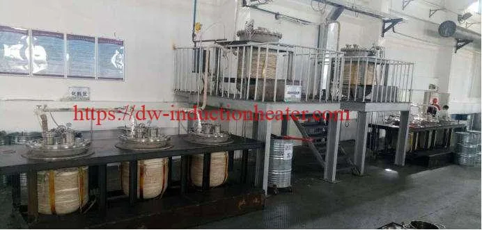
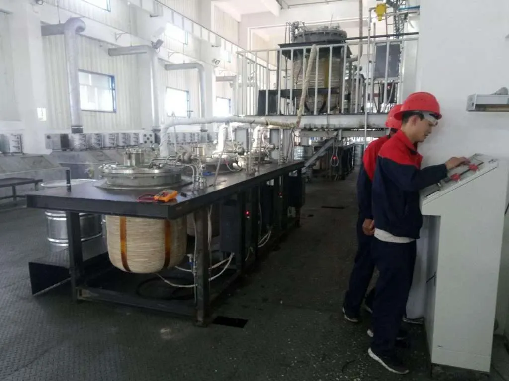
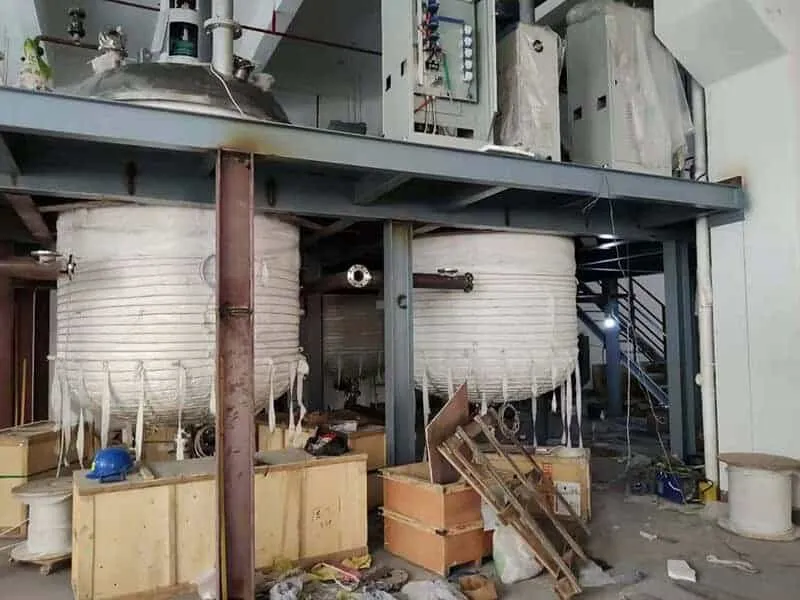
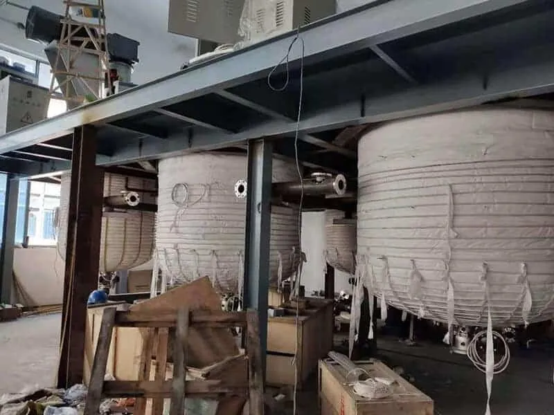
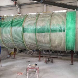
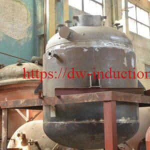
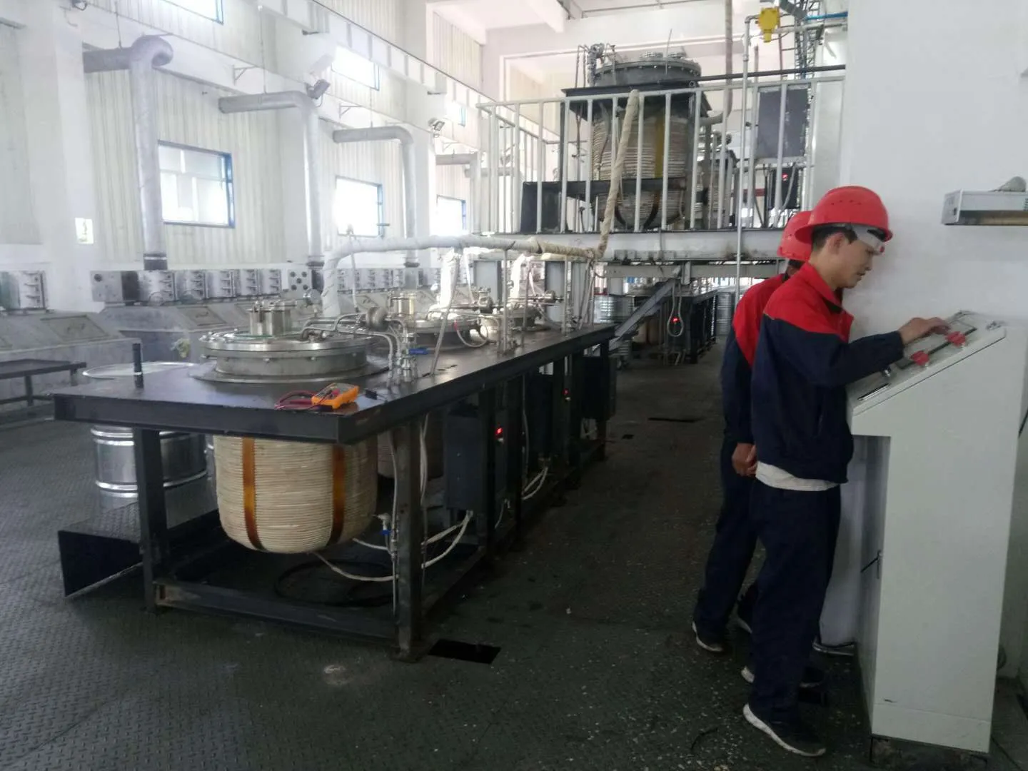
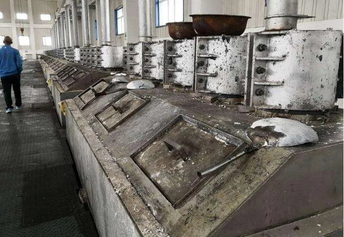
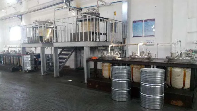
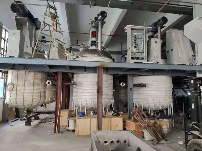
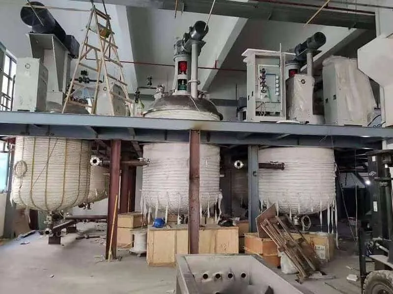
Stainless Steel Reactor Heating Induction
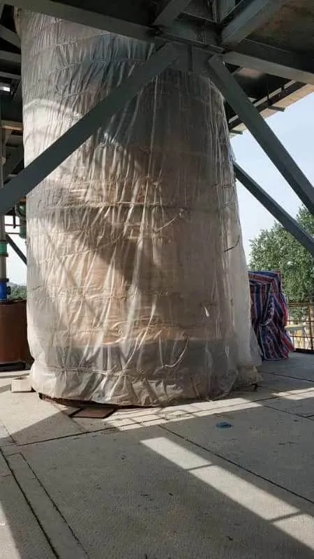
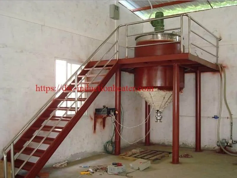
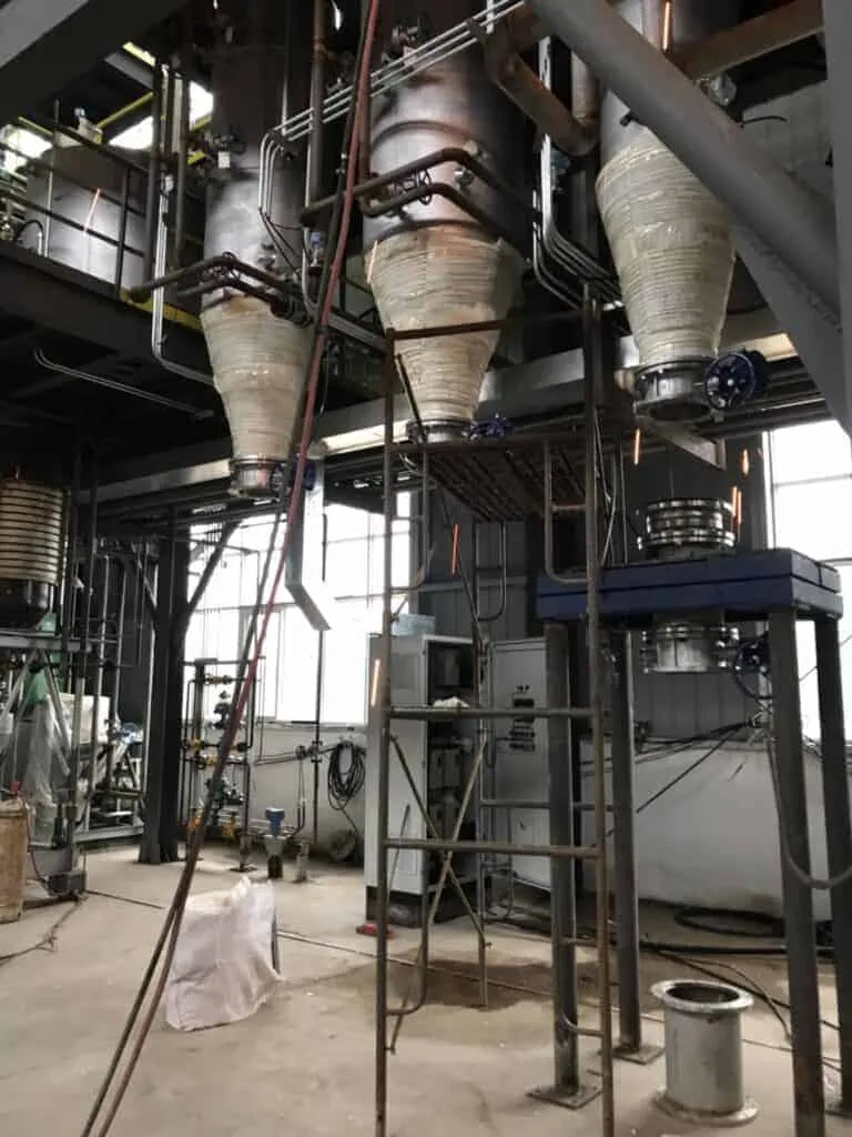
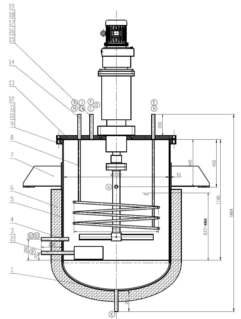
Induction Heating 304#, 310#, 316# stainless steel reaction kettle, stainless container
Induction heating chemical reactors for Reactors and Kettles, Autoclaves, Process Vessels, Storage and Settling Tanks, Baths, Vats and Still Pots, Pressure Vessels, Vapourisors and superheaters, Heat Exchangers, Rotary Drums, Pipes, Dual Fuel Heated Vessels and chemical vessels are the most advanced precision heating method available for any fluid processing.
 The traditional heating methods of various types of reactors basically use resistance wire, gas, fuel oil, biofuel or other indirect heating. Almost all heating methods use the principle of temperature difference to achieve heat transfer. On the one hand, this traditional heating process Heat energy will be wasted during the transfer process, and on the other hand, the production efficiency of the equipment will be reduced because the size of the temperature difference will affect the heating speed.
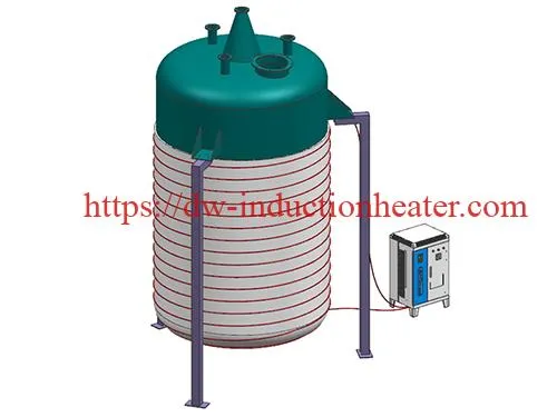
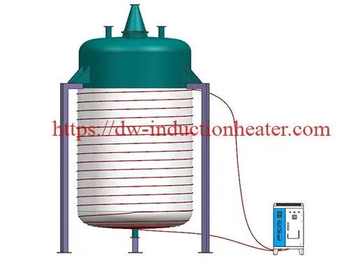
The electromagnetic induction heater uses the reaction kettle as the carrier, and replaces the traditional transfer heating by electromagnetic drive heating, and directly induces heating to the reaction kettle body, so the heating speed can be improved. At the same time, the coil can be arranged on the outer wall o f the reaction kettle, and the heating device will not be damaged due to the high temperature in the reaction kettle. At the same time, there is no emission caused by the heating process during the heating process, which solves the problem of low production efficiency of traditional heating equipment and maintenance of heating elements. Frequent problems and environmental pollution caused by burning.
- Energy efficient
Induction heating is over 98% efficient at converting electricity to heat, providing energy savings of 30% and more. - Safe and reliable
Coupled with intelligent control, the induction heating eliminates the need for open flame and heating mediums, ensuring a safer operation. - Eco-friendly
With no need for open flame, induction heating does not produce dust, odor, noise and hazardous gases, compliant with the requirements of National Energy Conservation Policy. - Digital control
Digital control system ensures accurate temperature control, offering an intelligent operation. - Compact structure, easy maintenance
We have induction heating machine from 1 KW ~ 500KW. The heating temperature 0~650 C. We can make suitable induction heating machine for different type reactor.
The advantage of induction heating for reacor heating:
1. Quickly heating speed with high heating effect
2. No physical contact between induction coil and heated vessel wall
3. Instant start-up and shut-down; no thermal inertia
4. Low heat loss
5. Precision product and vessel wall temperature control without over shoot
6. High energy input, ideal for automatic or micro-processor control
7. Safe hazard area or standard industrial operation at line voltage
8. Pollution free uniform heating at high efficiency
10. Low or high temperature
11. Simple and flexible to operate
12. Minimum maintenance
13. Consistent product quality
14. Heater is self-contained with minimum floor space requirement
15. Safty and stable for 24 hours working &More than 10 years working life
Induction heating coil designs are available to suit metallic vessel and tanks of most forms and shapes ranging from a few centimeters to several meters diameter or length. Mild steel, clad mild steel, solid stainless steel or non ferrous vessels can be successfully heated. Generally a minimum wall thickness of 6~10mm is recommended.
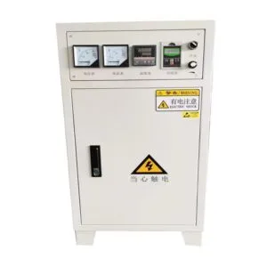
The induction weld preheating machine include:
1. induction heating power.
2. Induction heating coil.
3. Extend cable
4. K type thermocouple and so on.
Induction heating offers benefits not found in other systems: improved plant production efficiency and better operating conditions with no significant emission of heat to the surroundings.
Typical industries using induction process heating:
• Reactors and kettles.
• Adhesive and special coatings.
• Chemical, gas and oil.
• Food processing.
• Metallurgical and metal finishing and so on.
HLQ Induction Heating Chemical Reactor/Vessels System Manufacturer
We have over 20 years experience in induction heating and have developed, designed, manufactured, installed and commissioned Vessel and Pipe Heating systems to many countries all over the world.Due to the heating system being naturally simple and very reliable, the option of heating by induction should be regarded as the preferred choice.Induction heating embodies all the conveniences of electricity taken direct to the process and transformed to heat exactly where it is required. It can be applied successfully to virtually any vessel or pipe system needing a source of heat.
Induction offers many benefits unobtainable by other means and gives improved plant production efficiency and better operating conditions since there is no significant emission of heat to the surroundings. The system is particularly suitable for close control reaction processes such as the production of synthetic resins in a Hazard Area.
As each induction heating vessel is bespoke to each customers specific needs and requirements, we offer varying sizes with differing heat up rates. Our engineers have had many years of experience in evolving custom built induction heating systems for a wide range of applications in a wide range of industries. Heaters are designed to suit the precise requirements of the process and are constructed for quick fitting onto the vessel either in our works or on site.
UNIQUE BENEFITS
• No physical contact between induction coil and heated vessel wall.
• Rapid start-up and shut-down. No thermal inertia.
• Low heat loss
• Precision product and vessel wall temperature control without over shoot.
• High energy input. Ideal for automatic or micro-processor control
• Safe hazard area or standard industrial operation at line voltage.
• Pollution free uniform heating at high efficiency.
• Low running costs.
• Low or high temperature working.
• Simple and flexible to operate.
• Minimum maintenance.
• Consistent product quality.
• Heater self-contained on vessel generating minimum floor space requirement.
Induction heating coil designs are available to suit metallic vessels and tanks of most forms and shapes in current use. Ranging from a few centremetres to several metres diameter or length. Mild steel, clad mild steel, solid stainless steel or non ferrous vessels can all be successfully heated. Generally a minimum wall thickness of 6mm is recommended.
Unit rating designs range from 1KW to 1500KW. With induction heating systems there is no limit on power density input. Any limitation that exists is imposed by the maximum heat absorption capacity of the product, process or metallurgical characteristics of the vessel wall material.
Induction heating embodies all the conveniences of electricity taken direct to the process and transformed to heat exactly where it is required. Since heating takes place direct in the vessel wall in contact with the product and the heat losses are extremely low, the system is highly efficient (up to 90%).
Induction heating offers a great many benefits unobtainable by other means and gives improved plant production efficiency and better operating conditions since there is no significant emission of heat to the surroundings.
Typical industries using induction process heating:
• Reactors and kettles
• Adhesive and special coatings
• Chemical, gas and oil
• Food processing
• Metallurgical and metal finishing
• Preheating Welding
• Coating
• Mold heating
• Fitting&Unfitting
• Thermal Assembly
• Food Drying
• Pipeline Fluid Heating
• Tank & Vessel Heating and Insulation
The HLQ Induction In-Line Heater arrangement can be used for applications include:
• Air and Gas heating for Chemical and Food Processing
• Hot Oil Heating for Process and Edible Oils
• Vaporising and Superheating: Instant steam raising, low and high temperature / pressure (up to 800ºC at 100 bar)
Previous Vessel and Continuous Heater projects include:
Reactors and Kettles, Autoclaves, Process Vessels, Storage and Settling Tanks, Baths, Vats and Still Pots, Pressure Vessels, Vapourisors and superheaters, Heat Exchangers, Rotary Drums, Pipes, Dual Fuel Heated Vessels
Previous In-Line Heater project include:
High Pressure Super Heated Steam heaters, Regenerative Air Heaters, Lubricating Oil Heaters, Edible Oil and Cooking Oil Heaters, Gas heaters including Nitrogen, Nitrogen Argon and Catalytic Rich Gas (CRG) heaters.
Induction heating is a non-contact method of selectively heating electrically-conductive materials by applying an alternating magnetic field to induce an electric current, known as an eddy current, in the material, known as a susceptor, thereby heating the susceptor. Induction heating has been used in the metallurgical industry for many years for the purpose of heating metals, e.g. melting, refining, heat treating, welding, and soldering. Induction heating is practiced over a wide range of frequencies, from AC powerline frequencies as low as 50 Hz up to frequencies of tens of MHz.
At a given induction frequency the heating efficiency of the induction field increases when a longer conduction path is present in an object. Large solid work pieces may be heated with lower frequencies, while small objects require higher frequencies. For a given size object to be heated, too low a frequency provides inefficient heating since the energy in the induction field does not generate the desired intensity of eddy currents in the object. Too high a frequency, on the other hand, causes non-uniform heating since the energy in the induction field does not penetrate into the object and eddy currents are only induced at or near the surface. However, induction heating of gas-permeable metallic structures is not known in the prior art.
Prior art processes for gas phase catalytic reactions require that the catalyst have a high surface area in order for the reactant gas molecules to have maximum contact with the catalyst surface. The prior art processes typically use either a porous catalyst material or many small catalytic particles, suitably supported, to achieve the required surface area. These prior art processes rely on conduction, radiation or convection to provide the necessary heat to the catalyst. To achieve good selectivity of chemical reaction all portions of the reactants should experience uniform temperature and catalytic environment. For an endothermic reaction, the rate of heat delivery therefore needs to be as uniform as possible over the entire volume of the catalytic bed. Both conduction, and convection, as well as radiation, are inherently limited in their ability to provide the necessary rate and uniformity of heat delivery.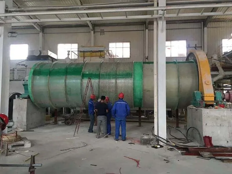
GB Patent 2210286 (GB ‘286), which is typical of the prior art, teaches mounting small catalyst particles that are not electrically conductive on a metallic support or doping the catalyst to render it electrically conductive. The metallic support or the doping material is induction heated and in turn heats the catalyst. This patent teaches the use of a ferromagnetic core passing centrally through the catalyst bed. The preferred material for the ferromagnetic core is silicon iron. Although useful for reactions up to about 600 degrees C., the apparatus of GB Patent 2210286 suffers from severe limitations at higher temperatures. The magnetic permeability of the ferromagnetic core would degrade significantly at higher temperatures. According to Erickson, C. J., “Handbook of Heating for Industry”, pp 84–85, the magnetic permeability of iron starts to degrade at 600 C and is effectively gone by 750 C. Since, in the arrangement of GB ‘286, the magnetic field in the catalyst bed depends upon the magnetic permeability of the ferromagnetic core, such an arrangement would not effectively heat a catalyst to temperatures in excess of 750 C, let alone reach the greater than 1000 C required for the production of HCN.
The apparatus of GB Patent 2210286 is also believed chemically unsuitable for the preparation of HCN. HCN is made by reacting ammonia and a hydrocarbon gas. It is known that iron causes the decomposition of ammonia at elevated temperatures. It is believed that the iron present in the ferromagnetic core and in the catalyst support within the reaction chamber of GB ‘286 would cause decomposition of the ammonia and would inhibit, rather than promote, the desired reaction of ammonia with a hydrocarbon to form HCN.
Hydrogen cyanide (HCN) is an important chemical with many uses in the chemical and mining industries. For example, HCN is a raw material for the manufacture of adiponitrile, acetone cyanohydrin, sodium cyanide, and intermediates in the manufacture of pesticides, agricultural products, chelating agents, and animal feed. HCN is a highly toxic liquid which boils at 26 degrees C., and as such, is subject to stringent packaging and transportation regulations. In some applications, HCN is needed at remote locations distant from large scale HCN manufacturing facilities. Shipment of HCN to such locations involves major hazards. Production of the HCN at sites at which it is to be used would avoid hazards encountered in its transportation, storage, and handling. Small scale on-site production of HCN, using prior art processes, would not be economically feasible. However, small scale, as well as large scale, on-site production of HCN is technically and economically feasible using the processes and apparatus of the present invention.
HCN can be produced when compounds containing hydrogen, nitrogen, and carbon are brought together at high temperatures, with or without a catalyst. For example, HCN is typically made by the reaction of ammonia and a hydrocarbon, a reaction which is highly endothermic. The three commercial processes for making HCN are the Blausaure aus Methan und Ammoniak (BMA), the Andrussow, and the Shawinigan processes. These processes can be distinguished by the method of heat generation and transfer, and by whether a catalyst is employed.
The Andrussow process uses the heat generated by combustion of a hydrocarbon gas and oxygen within the reactor volume to provide the heat of reaction. The BMA process uses the heat generated by an external combustion process to heat the outer surface of the reactor walls, which in turn heats the inner surface of the reactor walls and thus provides the heat of reaction. The Shawinigan process uses an electric current flowing through electrodes in a fluidized bed to provide the heat of reaction.
 In the Andrussow process, a mixture of natural gas (a hydrocarbon gas mixture high in methane), ammonia, and oxygen or air are reacted in the presence of a platinum catalyst. The catalyst typically comprises a number of layers of platinum/rhodium wire gauze. The quantity of oxygen is such that the partial combustion of the reactants provides sufficient energy to preheat the reactants to an operating temperature in excess of 1000° C. as well as the required heat of reaction for HCN formation. The reaction products are HCN, H2, H2O, CO, CO2, and trace amounts of higher nitrites, which must then be separated.
In the BMA process, a mixture of ammonia and methane flows inside non-porous ceramic tubes made of a high temperature refractory material. The inside of each tube is lined or coated with platinum particles. The tubes are placed in a high temperature furnace and externally heated. The heat is conducted through the ceramic wall to the catalyst surface, which is an integral part of the wall. The reaction is typically carried out at 1300° C. as the reactants contact the catalyst. The heat flux required is high due to the elevated reaction temperature, the large heat of reaction, and the fact that coking of the catalyst surface can occur below the reaction temperature, which deactivates the catalyst. Since each tube is typically about 1″ in diameter, a large number of tubes are needed to meet production requirements. Reaction products are HCN and hydrogen.
In the Shawinigan process, the energy required for reaction of a mixture consisting of propane and ammonia is provided by an electric current flowing between electrodes immersed in a fluidized bed of non-catalytic coke particles. The absence of a catalyst, as well as the absence of oxygen or air, in the Shawinigan process means that the reaction must be run at very high temperatures, typically in excess of 1500 degrees C. The higher temperatures required place even greater constraints on the materials of construction for the process.
While, as disclosed above, it is known that HCN can be produced by the reaction of NH3 and a hydrocarbon gas, such as CH4 or C3H8, in the presence of a Pt group metal catalyst, there is still a need to improve the efficiency of such processes, and related ones, so as to improve the economics of HCN production, especially for small scale production. It is particularly important to minimize energy use and ammonia breakthrough while maximizing the HCN production rate in comparison to the amount of precious metal catalyst used. Moreover, the catalyst should not detrimentally affect production of HCN by promoting undesirable reactions such as coking. Furthermore, it is desired to improve activity and life of catalysts used in this process. Significantly, a large part of the investment in production of HCN is in the platinum group catalyst. The present invention heats the catalyst directly, rather than indirectly as in the prior art, and thus accomplishes these desiderata.
 As previously discussed, relatively low frequency induction heating is known to provide good uniformity of heat delivery at high power levels to objects that have relatively long electrical conduction paths. When providing the reaction energy to an endothermic gas phase catalytic reaction, the heat needs to be directly delivered to the catalyst with minimum energy loss. The requirements of uniform and efficient heat delivery to a high-surface-area, gas-permeable catalyst mass seem to conflict with the capabilities of induction heating. The present invention is based on unexpected results obtained with a reactor configuration wherein the catalyst has a novel structural form. This structural form combines the features of: 1) an effectively long electrical conduction path length, which facilitates efficient direct induction heating of the catalyst in a uniform manner, and 2) a catalyst having a high surface area; these features cooperate to facilitate endothermic chemical reactions. The complete lack of iron in the reaction chamber facilitates the production of HCN by the reaction of NH3 and a hydrocarbon gas.
Induction Heating Power Calculation
Example: Atmospheric Pressure Reactor
Material: 304 stainless steel
Dimensions: 2m(diameter)*3m(height)
Wall thickness: 8mm
Reactor weight: 1000kg (approx.)
Volume: 7m3
Liquid material weight: 7t
Specific heat capacity of liquid material: 4200J/kg*ºC
Requirements: to heat from 20ºC to 280ºC within 3 hours
Heat calculation formula: Q=cm▲t+km
Power calculation formula: specific heat capacity J/(kg*ºC)×temperature differenceºC×weight KG ÷ time S = power W
i.e. P=4200J/kg*ºC×(280-20)ºC×7000kg÷10800s=707777W≈708kW
Conclusion
The theoretical power is 708kW, but the actual power is commonly increased by 20% because of taking the heat loss into consideration, that is, the actual power is 708kW*1.2≈850kW. Seven sets of 120kW induction heating system as a combination are required.
 Induction heating vessels reactors

