




Induction Brazing Soldering Machine
DW-HF-45KW High Frequency Induction Brazing & Soldering Machine
Quick Answer
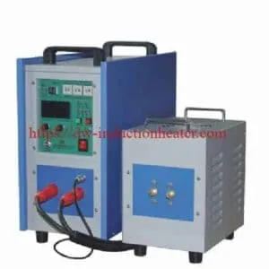
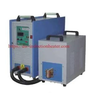
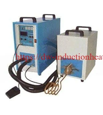
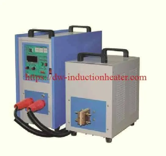
What is the DW-HF-45KW Induction Brazing and Soldering Machine? The HLQ DW-HF-45KW is a high-frequency induction heating system designed for industrial metal joining, including copper tube brazing, brass fitting brazing, carbide tool brazing, and selected electrical soldering applications. The manufacturer publishes a maximum oscillation rating of 45kVA, a maximum input rating of 50kVA, an operating frequency range of 30–80kHz, and a three-phase 380V, 50/60Hz electrical supply. The system uses an IGBT inverter, a separated heating unit, and application-specific water-cooled copper induction coils to generate localized electromagnetic heating.
Best-Fit Applications: HVAC copper pipe brazing, refrigeration tube connections, copper-to-brass fittings, carbide tool joining, electrical copper connectors, selected stainless steel assemblies, and industrial brazing workstations.
Engineering Selection: The DW-HF-45KW should be selected according to the joining process, base materials, filler metal, joint geometry, target temperature, effective heated mass, heating cycle, operating frequency, coil design, and cooling conditions. The published 45kVA maximum oscillation rating is not equivalent to 45kW of guaranteed useful heating power delivered to the workpiece.
Table of Contents
- What Is the DW-HF-45KW Induction Brazing & Soldering Machine?
- Key Applications
- Suitable Materials
- Working Principle
- Technical Specifications
- Recommended Model Selection
- Process Workflow
- Common Problems and Solutions
- Engineering Selection Guide
- Advantages and Limitations
- Why Choose HLQ?
- 10 Core FAQs
What Is the DW-HF-45KW Induction Brazing & Soldering Machine?
The DW-HF-45KW Induction Brazing and Soldering Machine is an industrial electromagnetic heating system designed to heat electrically conductive metal assemblies during brazing, soldering, and selected localized heat-treatment operations.
The system converts three-phase electrical power into high-frequency alternating current. This current flows through an induction coil, generating a changing magnetic field around the workpiece.
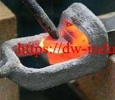
The changing magnetic field induces electrical currents in conductive metal components. Electrical resistance converts the induced currents into heat, allowing the joining area to reach the required processing temperature.
Unlike fusion welding, induction brazing and induction soldering do not require the base materials to melt. A compatible filler metal melts, wets the prepared joining surfaces, and solidifies to form the connection.
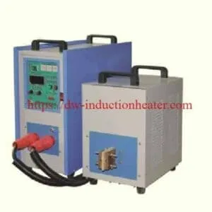
The DW-HF-45KW uses a separated equipment arrangement consisting of a main power unit and an extension unit. This configuration provides installation flexibility when the heating station must be positioned near industrial fixtures or production equipment.
Main Components of the DW-HF-45KW System
| Component | Function | Engineering Requirement |
|---|---|---|
| Main Power Supply | Converts industrial electrical input into controlled power for induction heating | Compatible electrical supply and protective devices |
| IGBT Inverter | Generates high-frequency alternating electrical current | Correct inverter rating and operating frequency |
| Resonant Matching Circuit | Matches the induction load to the inverter | Compatible coil inductance and load characteristics |
| Extension Unit | Provides a separated heating-head or transformer arrangement | Approved electrical and cooling connections |
| Induction Coil | Generates the alternating magnetic field | Application-specific geometry and cooling |
| Workpiece Fixture | Positions and supports the joint assembly | Repeatable alignment and suitable operating clearance |
| Control System | Regulates selected heating parameters | Appropriate power, timer, and protection functions |
| Cooling System | Removes heat from designated components | Approved water flow, pressure, and temperature |

Induction Brazing vs. Induction Soldering
Induction brazing and induction soldering both use electromagnetic induction as a heating method. The fundamental difference is the liquidus temperature of the filler metal.
Brazing uses a filler metal with a liquidus temperature above 450°C and below the solidus temperature of the base materials.
Soldering uses a filler metal with a liquidus temperature at or below 450°C.
Both processes require compatible base materials, correct surface preparation, suitable filler metal, and controlled heating.
| Parameter | Induction Brazing | Induction Soldering |
|---|---|---|
| Filler Metal Liquidus | Above 450°C | At or below 450°C |
| Base Metal Melting | Not required | Not required |
| Joining Mechanism | Filler wetting and capillary action | Solder wetting and joint formation |
| Typical Materials | Copper, brass, steel, stainless steel, carbide assemblies | Copper terminals, connectors, selected electronic and electrical assemblies |
| Typical Applications | HVAC tubes, carbide tools, industrial fittings | Electrical contacts, terminals, low-temperature joints |
| Main Process Concern | Joint temperature, filler flow, oxide control | Controlled reflow and protection of nearby components |
| Coil Design Priority | Heating the complete brazing interface | Localized heating with limited thermal exposure |
Technical Note: The DW-HF-45KW operating frequency range does not establish that every low-temperature soldering application is suitable. Very small electronic joints may require lower-power or higher-frequency equipment, specialized coils, and more precise temperature control.
Key Applications
The DW-HF-45KW can be considered for different industrial joining and heating applications. The correct configuration depends on the material combination, workpiece geometry, filler metal, and production requirements.
1. Copper Tube Induction Brazing
Induction brazing is commonly used to join copper tubes, elbows, connectors, and compatible fittings.
A suitably designed induction coil concentrates the heating field around the joining area. The base materials are heated to the required brazing temperature so that the selected filler metal can wet the surfaces and flow into the joint.
The process is relevant to HVAC, refrigeration, heat exchangers, and industrial copper piping.
2. Copper-to-Brass Fitting Brazing
Copper tubes and brass fittings may be joined through induction brazing using a compatible filler metal.
The heating process must account for differences in component geometry, thermal conductivity, and mass.
Excessive heating of brass components should be avoided because zinc-containing alloys can be sensitive to overheating and may produce hazardous fumes.
3. Carbide Tool Brazing
Induction heating can be used to braze suitable carbide cutting tips to steel tool holders.
The induction coil must provide the required heating at the brazing interface while limiting excessive temperature gradients between the carbide and steel components.
The filler metal, joint clearance, and cooling procedure must be selected according to the tool requirements.
4. HVAC and Refrigeration Connections
Induction brazing can be integrated into manufacturing processes involving copper refrigeration pipes, compressor connections, manifolds, and related fittings.
Repeatable coil positioning and controlled heating cycles support consistent production when the complete joining procedure has been validated.
5. Electrical Connector Soldering
The equipment may be evaluated for soldering suitable copper connectors, busbars, terminals, and other electrically conductive assemblies.
However, the heating cycle must be selected according to the solder alloy and the temperature limits of nearby insulation or other sensitive components.
6. Industrial Metal Joining
Selected steel, stainless steel, copper, and brass components can be heated for compatible brazing operations.
Dissimilar-material assemblies may require specialized filler metals, carefully controlled temperatures, and customized induction coil geometry.
| Application | Materials | Process | Main Engineering Requirement |
|---|---|---|---|
| HVAC Copper Tube Joint | Copper-to-copper | Brazing | Circumferential joint heating and filler flow |
| Brass Valve Connection | Copper-to-brass | Brazing | Balanced heating of dissimilar components |
| Heat Exchanger Connection | Copper and compatible alloys | Brazing | Access and repeatable joint positioning |
| Carbide Tool Assembly | Steel and carbide | Brazing | Thermal stress and filler compatibility |
| Electrical Copper Terminal | Copper and compatible metals | Soldering or brazing | Appropriate filler and temperature control |
| Stainless Steel Joint | Stainless steel and compatible metals | Brazing | Oxide control and qualified filler metal |
| Diamond Tool Segment | Tool steel and cutting segment | Brazing | Localized heating and thermal damage prevention |
For an application example involving copper tube joints, see HLQ’s induction brazing copper tubing application.
Suitable Materials
Induction brazing and soldering can be used with many electrically conductive metals. However, electromagnetic heating suitability and metallurgical joining compatibility must be evaluated separately.
Electrical resistivity, magnetic permeability, thermal conductivity, joint geometry, and filler metal properties influence the required equipment configuration.
Base Material Compatibility
| Material Combination | Heating Characteristics | Joining Considerations |
|---|---|---|
| Copper-to-Copper | High electrical and thermal conductivity | Suitable filler metal, capillary clearance, and heat balance |
| Copper-to-Brass | Different thermal properties and component masses | Qualified filler and suitable oxide control |
| Copper-to-Stainless Steel | Dissimilar electrical and thermal properties | Qualified filler, flux or atmosphere, and joint design |
| Steel-to-Carbide | Different thermal expansion behavior | Thermal stress management and compatible filler |
| Brass-to-Brass | Conductive copper-zinc alloy | Temperature control and zinc-related process considerations |
| Copper Electrical Contacts | High conductivity; potentially temperature-sensitive surroundings | Suitable solder alloy and controlled local heating |
| Selected Nickel Alloys | Alloy-specific electrical and thermal properties | Qualified filler metal and atmosphere requirements |
Brazing Filler Metal Selection
A suitable filler metal must be selected according to the base materials, intended service environment, joint design, and mechanical requirements.
Induction heating can supply the required thermal energy, but it cannot compensate for an incompatible brazing alloy.
| Joint Materials | Potential Filler Family | Engineering Consideration |
|---|---|---|
| Copper-to-Copper | Qualified copper-phosphorus or copper-phosphorus-silver alloys | Check joint fit, service environment, and alloy suitability |
| Copper-to-Brass | Compatible silver-based or other qualified brazing filler | Evaluate flux requirements and oxidation |
| Copper-to-Stainless Steel | Qualified silver-based or other suitable filler | Avoid unsuitable phosphorus-bearing fillers on ferrous or nickel-containing materials |
| Steel-to-Carbide | Qualified carbide-brazing filler or suitable silver-based alloy | Consider differential expansion and residual stress |
| Steel-to-Steel | Application-qualified silver, copper, or other compatible brazing alloys | Verify joint strength and operating conditions |
Solder Alloy Selection
For induction soldering, the filler metal must be selected according to the electrical, mechanical, and thermal requirements of the joint.
Common solder families may include tin-based alloys, but the actual solder specification must be selected for the application.
| Parameter | Requirement | Potential Problem |
|---|---|---|
| Solder Alloy | Suitable liquidus temperature and joint properties | Incomplete reflow or unsuitable service performance |
| Flux | Compatible with the solder and base materials | Poor wetting or harmful residues |
| Joint Temperature | Above the required solder-flow temperature | Cold solder joints |
| Temperature-Sensitive Parts | Remain within specified limits | Insulation or component damage |
| Heating Time | Sufficient for uniform joint heating | Overheating or incomplete solder flow |
| Post-Solder Inspection | Verify wetting and electrical or mechanical requirements | Undetected defects |
For additional soldering examples, review HLQ’s induction soldering applications and technical examples.
Working Principle
The DW-HF-45KW operates according to electromagnetic induction.
The main power supply converts three-phase industrial electricity into high-frequency alternating current using an inverter-based electrical circuit.
This current flows through a water-cooled copper induction coil and generates a changing magnetic field.
When a conductive metal component is positioned within the effective magnetic field, electrical currents are induced inside the workpiece.
Electrical resistance converts the induced currents into heat.
During brazing or soldering, the base materials are heated to the required joining temperature. The selected filler metal melts, wets the prepared surfaces, and forms the joint after cooling.
Electromagnetic Induction Heating Process
| Step | Component | Function |
|---|---|---|
| 1 | Three-Phase Electrical Supply | Provides electrical input power |
| 2 | IGBT Power Inverter | Generates high-frequency alternating electrical current |
| 3 | Resonant Matching Circuit | Matches the induction load to the power stage |
| 4 | Copper Induction Coil | Produces a changing magnetic field |
| 5 | Metal Workpiece | Absorbs electromagnetic energy and generates heat |
| 6 | Filler Metal | Melts and wets the joining surfaces |
| 7 | Cooling and Solidification | Forms the completed joint |
| 8 | Quality Inspection | Verifies joint acceptance requirements |
Induction Frequency and Heating Distribution
The DW-HF-45KW product page lists an operating frequency range of 30–80kHz.
Operating frequency influences the distribution of induced electrical currents within the workpiece.
Under simplified electromagnetic conditions, higher frequencies produce a smaller reference electrical penetration depth.
However, the final temperature distribution also depends on heating duration, thermal conduction, material properties, and workpiece geometry.
For a suitable homogeneous material, the reference electrical skin depth can be estimated using:
δ = √[ρ / (π × f × μ)]
Where:
- δ = Reference electrical skin depth, in meters.
- ρ = Electrical resistivity, in Ω·m.
- f = Operating frequency, in Hz.
- μ = Absolute magnetic permeability, in H/m.
Engineering Note: Electrical skin depth is not identical to the final heating depth or temperature penetration depth. Actual heating performance must be evaluated under the selected operating conditions.
Induction Coil Design
The induction coil determines the distribution of the electromagnetic field around the workpiece.
Its geometry, turn spacing, active heating length, coupling distance, and electrical matching influence the heating pattern.
For copper tube brazing, helical coils are frequently considered because they can surround the joint.
For restricted-access assemblies, split, U-shaped, pancake, or custom-profile coils may be required.
| Application | Recommended Coil Concept | Design Priority |
|---|---|---|
| Copper Tube Brazing | Helical Coil | Heat the joint around its circumference |
| Brass Fitting Brazing | Helical or U-Shaped Coil | Balanced heating of the joining components |
| Restricted HVAC Connections | Split or Custom-Profile Coil | Mechanical access and positioning |
| Carbide Tool Brazing | Pancake or Profile Coil | Localized heating of the brazing interface |
| Electrical Connector Soldering | Small Helical or Profile Coil | Control local temperature and protect nearby components |
| Heat Exchanger Connections | Specialized Multi-Position Coil | Repeatable heating in restricted spaces |
For specialized coil configurations, see HLQ’s custom induction brazing coil design guide.

Technical Specifications
The following technical specifications are based on the original HLQ DW-HF-45KW product page.
Actual electrical ratings, cooling requirements, operating duty, and supplied control functions should be verified using the technical documentation for the delivered machine.
DW-HF-45KW Published Specifications
| Parameter | Published Specification | Engineering Notes |
|---|---|---|
| Model | DW-HF-45KW | Manufacturer-published designation |
| Equipment Type | High-Frequency Induction Heating Equipment | Brazing, soldering, and localized metal heating |
| Input Voltage | 3 × 380V AC | Three-phase industrial power supply |
| Input Frequency | 50/60Hz | Utility supply frequency |
| Maximum Oscillation Rating | 45kVA | Published electrical rating |
| Maximum Input Rating | 50kVA | Published input apparent-power rating |
| Operating Frequency | 30–80kHz | Actual frequency depends on load matching |
| Oscillation Current | 15–90A | Not necessarily mains input current |
| Cooling Method | Water Cooling | Required for designated electrical and coil components |
| Cooling Water Flow | At least 6L/min | Confirm total circuit requirements |
| Cooling Pressure Reference | 0.3MPa | Confirm whether maximum permitted pressure |
| Duty Cycle | 100% at 30°C | Manufacturer claim requiring defined operating conditions |
| Published Equipment Weight | 75kg | Confirm total or net weight |
| Main Unit Dimensions | 550 × 240 × 535mm | Length × Width × Height |
| Extension Unit Dimensions | 470 × 265 × 440mm | Length × Width × Height |
| Interconnecting Cable | 2m | Changes require electrical matching approval |
| Inverter Technology | IGBT | Verify actual supplied power-stage version |
| Control Functions | Constant-current or constant-power operation described | Confirm actual available modes |
| Timer Control | Available on timer-equipped models | Confirm standard or optional configuration |
Electrical Rating Interpretation
The manufacturer’s original specifications list a maximum oscillation rating of 45kVA and a maximum input rating of 50kVA.
Apparent electrical power, active electrical power, inverter output power, and useful workpiece heating power are different quantities.
| Parameter | Meaning | Required Verification |
|---|---|---|
| Input Apparent Power | Electrical apparent power supplied to the machine | Rated kVA |
| Input Active Power | Actual electrical power consumption | Measured input kW |
| Inverter Output | Electrical power delivered to the induction circuit | Manufacturer-defined rating |
| Useful Heating Power | Thermal power absorbed by the workpiece | Application-specific test |
| Power Factor | Relationship between input active and apparent power | Actual supply-side measurement |
Three-Phase Input Current Calculation
For a balanced three-phase electrical system:
S = √3 × Vline × Iline
Where S is apparent power, Vline is line voltage, and Iline is line current.
For a theoretical 50kVA three-phase input at 380V, the corresponding line current is approximately 76A.
This is a reference calculation, not a verified DW-HF-45KW operating-current measurement.
Cooling System Requirements
The DW-HF-45KW is a water-cooled induction heating system.
The cooling circuit must provide sufficient heat removal from the induction coil and designated power electronics.
| Cooling Parameter | Published or Required Information | Engineering Verification |
|---|---|---|
| Cooling Medium | Water | Confirm manufacturer-approved quality |
| Published Water Flow | ≥6L/min | Confirm total system requirement |
| Published Pressure Reference | 0.3MPa | Confirm allowable inlet-pressure range |
| Inlet Temperature | Not specified on the target page | Confirm operating limit |
| Cooling Water Quality | Not fully specified | Verify filtration, hardness, conductivity, and corrosion requirements |
| Cooling Circuit Integrity | Leak-free operation | Inspect hoses and connections |
| Water-Flow Protection | Water-failure protection described | Verify installed interlock |
| Cooling Capacity | Application-dependent | Size according to total heat rejection |
Illustrative Cooling Water Calculation
The theoretical heat removed by a water-cooling circuit can be estimated using:
P = mflow × Cp × ΔT
For an illustrative water flow of 6L/min and a water temperature increase of 8°C, the theoretical heat removal is approximately 3.34kW.
This value is an engineering example, not a measured DW-HF-45KW cooling load.
Recommended Model Selection
The correct induction brazing or soldering machine must be selected according to the complete joining process rather than nominal machine rating alone.
Joint mass, filler-metal melting temperature, heating cycle, operating frequency, and coil geometry all influence the required equipment.
Application-Based Model Selection
| Application | Material | Power Class to Evaluate | Frequency Consideration |
|---|---|---|---|
| Small Copper Tube Brazing | Copper | DW-HF-15 / DW-HF-25 | Application-specific |
| Medium Copper Tube Brazing | Copper and brass | DW-HF-25 / DW-HF-35 | Matched to joint geometry |
| Larger Copper Brazing Assemblies | Copper and compatible alloys | DW-HF-35 / DW-HF-45 | Matched to effective heated mass and coil |
| Carbide Tool Brazing | Steel and carbide | DW-HF-35 / DW-HF-45 candidates | Selected for localized heating requirements |
| Electrical Terminal Soldering | Copper and compatible metals | Smaller HF or specialized UHF system | Depends on solder temperature and local heating needs |
| Heat Exchanger Brazing | Copper and brass | DW-HF-45 or project-specific system | Depends on the number and size of joints |
| Heavy Metal Heating | Steel, copper, or other alloys | Higher-power or alternative-frequency system | Determine from thermal load and required heating depth |
Selection Qualification: The table above provides initial equipment-screening categories rather than guaranteed model capacities. Final selection requires material and workpiece information and, where necessary, representative application testing.
DW-HF Product Family Comparison
| Product | Published Power Class | Typical Positioning | Engineering Consideration |
|---|---|---|---|
| DW-HF-15 | 15kVA class | Small localized heating and joining | Verify electrical input and actual frequency variant |
| DW-HF-25 | 25kVA class | Copper brazing and small component heating | Confirm process mass and cycle time |
| DW-HF-35 | 35kVA class | Medium localized brazing and joining | Match to coil and cooling requirements |
| DW-HF-45 | 45kVA class | Industrial brazing and soldering equipment | Confirm electrical ratings and application performance |
| DW-HF-60 | 60kVA class | Higher heating-load applications | Verify required electrical and cooling utilities |
| DW-UHF Series | Multiple output classes | Specialized high-frequency or ultra-high-frequency joining | Consider very small components or higher frequency requirements |
For the general equipment configuration and other applications of this power class, review HLQ’s DW-HF-45KW high-frequency induction heating equipment guide.
Process Workflow
A controlled induction brazing or soldering process involves material identification, joint preparation, filler selection, coil positioning, heating, cooling, and inspection.
Standard Induction Brazing Process
| Step | Operation | Engineering Objective |
|---|---|---|
| 1 | Material Identification | Confirm base materials and joining requirements |
| 2 | Surface Preparation | Remove contamination and harmful oxides |
| 3 | Joint Assembly | Maintain specified clearance and alignment |
| 4 | Filler Metal Selection | Use a compatible brazing alloy |
| 5 | Induction Coil Positioning | Maintain suitable electromagnetic coupling |
| 6 | Cooling System Inspection | Verify approved water flow and temperature |
| 7 | Induction Heating | Raise the joint to the required brazing temperature |
| 8 | Filler Metal Flow | Allow complete wetting and joint filling |
| 9 | Controlled Cooling | Allow satisfactory filler solidification |
| 10 | Quality Inspection | Verify joint integrity and applicable acceptance criteria |
Induction Soldering Process
Induction soldering follows a related workflow but operates with a filler metal whose liquidus temperature does not exceed 450°C.
Many soldering applications require tighter control of thermal exposure because nearby electrical insulation, coatings, or other components may be temperature-sensitive.
| Stage | Requirement | Quality Risk |
|---|---|---|
| Cleaning | Compatible surface preparation | Poor solder wetting |
| Solder Placement | Correct solder volume and position | Insufficient or excessive solder |
| Flux Application | Suitable flux and residue control | Incomplete wetting or contamination |
| Coil Positioning | Controlled local heating | Heating of sensitive components |
| Heating Cycle | Correct solder reflow temperature | Cold joints or overheating |
| Cooling | Suitable solidification conditions | Disturbed or defective joints |
| Inspection | Relevant electrical and mechanical acceptance tests | Undetected joint defects |
Control System and Production Repeatability
The DW-HF-45KW product page describes constant-current and constant-power operation, along with timer functions available on selected configurations.
For industrial production, these functions can help establish repeatable heating cycles.
The exact control modes, timer ranges, and temperature-monitoring options must be verified for the supplied machine.
| Parameter | Purpose | Verification |
|---|---|---|
| Heating Power | Controls the applied electrical heating load | Record loaded operating conditions |
| Operating Frequency | Influences electromagnetic current distribution | Confirm actual loaded frequency |
| Heating Time | Defines the selected thermal cycle | Verify repeatability |
| Joint Temperature | Confirms suitable joining conditions | Use an appropriate calibrated measurement method |
| Coil Position | Maintains electromagnetic coupling | Fixture inspection |
| Cooling Flow | Protects the machine and coil | Flow measurement and interlock verification |
| Joint Quality | Confirms process acceptance | Visual, leak, electrical, or mechanical testing as applicable |
Common Problems and Solutions
Induction brazing and soldering defects may result from incorrect heating conditions, unsuitable filler metals, joint contamination, inconsistent coil positioning, or electrical and cooling problems.
| Problem | Possible Cause | Recommended Solution |
|---|---|---|
| Incomplete Brazing Filler Flow | Insufficient joint temperature or poor wetting | Verify joint temperature, surface preparation, and filler compatibility |
| Uneven Joint Heating | Incorrect coil geometry or positioning | Review field distribution and fixture alignment |
| Excessive Heating Time | Poor coupling or excessive heated mass | Review coil design and useful power delivery |
| Cold Solder Joint | Insufficient reflow temperature or inadequate solder wetting | Verify solder specification, flux, and heating cycle |
| Excessive Oxidation | Overheating or inadequate oxide control | Review process temperature, heating time, and atmosphere |
| Weak Brazed Joint | Incorrect filler metal or unsuitable joint clearance | Verify joint design and filler compatibility |
| Joint Porosity | Contamination, trapped gases, or unsuitable filler flow | Improve preparation and validate the brazing procedure |
| Coil Overheating | Insufficient cooling or excessive electrical losses | Stop operation and inspect water flow and electrical conditions |
| Water-Cooling Alarm | Insufficient flow, blockage, or excessive coolant temperature | Restore approved cooling conditions before operation |
| Overcurrent Protection | Electrical mismatch or component fault | Isolate the equipment and conduct qualified electrical inspection |
| Unstable Frequency | Changing load or resonant matching problem | Verify coil and matching-network compatibility |
| Inconsistent Production Quality | Variable positioning, material, or heating cycle | Improve fixture repeatability and validate the process recipe |
Engineering Selection Guide
Correct induction brazing and soldering machine selection begins with the complete joining process rather than only the advertised power rating.
Step 1: Define the Joining Process
Determine whether the application requires induction brazing or induction soldering.
The process classification depends on the liquidus temperature of the selected filler metal.
Step 2: Identify the Base Materials
Specify the actual metal grades, component dimensions, wall thicknesses, and relevant coatings.
Step 3: Select the Filler Metal
Choose a compatible filler alloy and confirm the melting range, flux requirements, joint properties, and service conditions.
Step 4: Evaluate Joint Geometry
Determine joint clearance, overlap length, accessibility, surrounding conductive materials, and available coil clearance.
Step 5: Define the Target Temperature
Specify the required joining temperature according to the filler metal and base-material limitations.
Step 6: Calculate the Effective Heated Mass
The effective heated mass may include only the joint and adjacent metal regions that become hot during the heating cycle.
This mass may be significantly different from the total weight of the assembly.
Step 7: Estimate Heating Energy
For a simplified sensible-heating calculation:
Q = m × Cp × ΔT
Where:
- Q = Theoretical useful thermal energy, kJ.
- m = Effective heated mass, kg.
- Cp = Approximate mean specific heat capacity, kJ/kg·K.
- ΔT = Temperature increase, K.
Engineering Example A: Copper Brazing
Consider a hypothetical copper joint assembly with an effective heated mass of 0.30kg.
Assume the copper is heated from 25°C to 725°C using an approximate mean specific heat capacity of 0.43kJ/kg·K.
The theoretical heating energy is:
Q = 0.30 × 0.43 × 700 = 90.3kJ
This is equivalent to approximately 0.0251kWh of useful thermal energy.
| Parameter | Value | Data Status |
|---|---|---|
| Material | Copper | Illustrative example |
| Effective Heated Mass | 0.30kg | Assumed |
| Initial Temperature | 25°C | Assumed |
| Target Temperature | 725°C | Assumed |
| Temperature Increase | 700K | Calculated |
| Mean Specific Heat | 0.43kJ/kg·K | Approximate assumption |
| Theoretical Heating Energy | 90.3kJ | Calculated |
| Equivalent Thermal Energy | 0.0251kWh | Calculated |
Engineering Example B: Copper Connector Soldering
Consider a hypothetical copper connector with an effective heated mass of 0.08kg.
Assume the connector is heated from 25°C to 240°C using an approximate mean specific heat capacity of 0.39kJ/kg·K.
The theoretical heating energy is:
Q = 0.08 × 0.39 × 215 = 6.708kJ
This is equivalent to approximately 0.00186kWh of useful thermal energy.
| Parameter | Value | Data Status |
|---|---|---|
| Material | Copper | Illustrative example |
| Effective Heated Mass | 0.08kg | Assumed |
| Initial Temperature | 25°C | Assumed |
| Target Temperature | 240°C | Assumed |
| Temperature Increase | 215K | Calculated |
| Mean Specific Heat | 0.39kJ/kg·K | Approximate assumption |
| Theoretical Heating Energy | 6.708kJ | Calculated |
| Equivalent Thermal Energy | 0.00186kWh | Calculated |
Step 8: Compare Heating Time and Power
For the same theoretical copper brazing heat requirement of 90.3kJ, the useful thermal power changes with heating time.
| Heating Time | Useful Thermal Power | Hypothetical Electrical Input at 50% Overall Efficiency |
|---|---|---|
| 8 seconds | 11.29kW | 22.58kW |
| 10 seconds | 9.03kW | 18.06kW |
| 15 seconds | 6.02kW | 12.04kW |
| 20 seconds | 4.52kW | 9.03kW |
| 30 seconds | 3.01kW | 6.02kW |
| 45 seconds | 2.01kW | 4.01kW |
Engineering Qualification: These figures are theoretical estimates rather than measured DW-HF-45KW performance. The assumed 50% electrical-to-workpiece heating efficiency is used only to illustrate the relationship between useful heating energy and electrical input.
The calculations exclude detailed temperature-dependent material properties, fixture heating, filler melting, electromagnetic losses, radiation, and other process effects.
Step 9: Select the Induction Coil
Choose a coil according to joint dimensions, workpiece accessibility, electrical matching, and required temperature distribution.
Step 10: Verify Electrical and Cooling Requirements
Confirm the three-phase electrical supply, actual input current, power factor, cooling-water flow, inlet pressure, operating temperature, and protection functions.
Step 11: Validate the Application
Where practical, perform a representative application test using actual materials and joint assemblies.
Record the heating cycle, joint temperature, filler-metal flow, electrical input, cooling conditions, and applicable quality results.
Published HLQ Application Reference
HLQ has published a separate copper tube induction brazing test using a DW-UHF-10KW induction system and an available split laboratory coil.
The reported test involved heavy-wall 5/16-inch copper tubing and brazing paste, with a temperature reference of approximately 815°C and a heating time of approximately 5.0–5.2 seconds.
| Parameter | Published Information | Qualification |
|---|---|---|
| Application | Copper Tube Brazing | Related induction joining process |
| Equipment | DW-UHF-10KW | Not a DW-HF-45KW test |
| Material | Copper Tubing | Heavy-wall 5/16-inch test tubing |
| Induction Coil | Split Laboratory Coil | Production coil may differ |
| Brazing Material | 505 Alloy Brazing Paste | As reported in the original application |
| Temperature Reference | Approximately 815°C | Published application value |
| Heating Time | Approximately 5.0–5.2 seconds | Specific reported test result |
| DW-HF-45KW Performance | Not measured in this test | Separate validation required |
This example demonstrates the importance of coil design, workpiece positioning, and controlled heating during induction brazing.
It does not establish guaranteed DW-HF-45KW heating time or production capacity.
Recommended Factory Acceptance Test
| Test Item | Verification Method | Acceptance Requirement |
|---|---|---|
| Electrical Input | Measure input voltage, current, and power | Approved electrical limits |
| Operating Frequency | Record actual loaded frequency | Approved operating range |
| Heating Time | Measure representative cycles | Agreed process duration |
| Joint Temperature | Use a suitable calibrated measurement method | Specified joining temperature |
| Filler Flow | Inspect the completed joint | Acceptable wetting and distribution |
| Cooling Water Flow | Measure actual circulation | Manufacturer-specified minimum |
| Cooling Water Pressure | Measure operating pressure | Approved pressure range |
| Coil Compatibility | Verify electrical matching and mechanical clearance | Stable operating conditions |
| Protection Functions | Test defined alarms and interlocks | Safe fault response |
| Joint Quality | Visual, leak, electrical, or mechanical inspection as applicable | Agreed acceptance criteria |
Advantages and Limitations
Advantages of DW-HF-45KW Induction Brazing and Soldering Equipment
| Advantage | Engineering Benefit |
|---|---|
| Localized Heating | Allows heating energy to be concentrated around the joining region |
| Adjustable Heating Power | Supports controlled heating cycles |
| No Direct Burner Flame | Eliminates the need for direct combustion at the heating station |
| Repeatable Heating | Supports consistent operation when positioning and process parameters are controlled |
| Custom Induction Coils | Allows different joint geometries to be considered |
| Separated Equipment Arrangement | Provides installation flexibility |
| Industrial Automation Compatibility | Can be integrated with suitable fixtures and controls |
| Process Timer Options | Supports repeatable heating cycles when included |
| Application Flexibility | Supports evaluation of different brazing and soldering processes |
Limitations and Engineering Considerations
| Limitation | Engineering Consideration |
|---|---|
| Power Capacity | Large assemblies may require higher-power equipment |
| Workpiece-Specific Coil | Different joints may require dedicated induction coils |
| Filler Metal Compatibility | Induction heating cannot compensate for an unsuitable filler metal |
| Joint Preparation | Contamination and oxides can prevent satisfactory wetting |
| Electrical Supply | Requires a suitable three-phase industrial installation |
| Cooling Requirements | Water-cooled components require reliable circulation |
| Low-Temperature Soldering | Very small or sensitive joints may require specialized lower-power or higher-frequency equipment |
| Duty Cycle | Continuous-duty claims require verification under defined conditions |
| Equipment Ratings | 45kVA does not equal guaranteed useful thermal power |
| Process Qualification | Critical joints require representative testing |

Why Choose HLQ?
HLQ Induction Equipment Co., Ltd. provides induction heating equipment for brazing, soldering, hardening, annealing, forging, melting, and other industrial metalworking applications.
The DW-HF-45KW belongs to HLQ’s high-frequency induction heating product range and can be evaluated for different industrial joining processes.
Application-Based Equipment Selection
Equipment selection can be based on material properties, joint dimensions, filler metal, target temperature, heating cycle, production requirements, and available factory utilities.
IGBT High-Frequency Inverter Technology
The original DW-HF-45KW product page describes IGBT inverter technology and high-frequency operation.
The actual electrical configuration should be verified for the supplied machine.
Custom Induction Coil Solutions
Different brazing and soldering assemblies may require different coil geometries.
Coil selection should consider electromagnetic coupling, operating frequency, electrical matching, mechanical clearance, and cooling.
Industrial Joining Applications
The equipment can be considered for copper tube joints, brass fittings, carbide tools, electrical connectors, and other qualified industrial joining processes.
Engineering Process Validation
Representative application testing can help verify the required heating time, joint temperature, filler-metal flow, and production repeatability.
For a wider selection of joining equipment, review HLQ’s industrial induction brazing machine range.
10 Core FAQs
1. What is the DW-HF-45KW induction brazing and soldering machine?
The DW-HF-45KW is a high-frequency induction heating system designed for industrial joining and localized metal heating. Typical applications include copper tube brazing, brass fitting brazing, carbide tool joining, and selected electrical soldering operations.
2. What is the rated power of the DW-HF-45KW?
The original product page publishes a maximum oscillation rating of 45kVA and a maximum input rating of 50kVA. These electrical ratings do not establish 45kW of useful thermal power absorbed by a workpiece.
3. What electrical supply does the machine require?
The published electrical input is three-phase 380V, 50/60Hz. Actual input current, electrical protection, voltage tolerance, and installation requirements should be confirmed from the equipment datasheet.
4. What is the operating frequency?
The original product page lists an operating frequency range of 30–80kHz. The actual loaded frequency depends on the induction coil, resonant matching, and workpiece characteristics.
5. What is the difference between induction brazing and induction soldering?
Induction brazing uses a filler metal with a liquidus temperature above 450°C, while induction soldering uses a filler with a liquidus temperature at or below 450°C. Both processes use induction heating and do not intentionally melt the base materials.
6. Can the DW-HF-45KW braze copper tubes and brass fittings?
Yes, the equipment can be considered for suitable copper tube and brass fitting brazing applications. Actual performance depends on joint geometry, component mass, filler metal, induction coil, and heating conditions.
7. Can the DW-HF-45KW solder copper electrical connectors?
It may be suitable for selected electrical connector soldering applications. However, the solder alloy, connector mass, nearby insulation, and required temperature control must be evaluated. Very small or temperature-sensitive assemblies may require more specialized equipment.
8. How much cooling water is required?
The original product page lists a cooling-water flow of at least 6L/min and includes a 0.3MPa pressure reference. The required total flow, permitted operating pressure, inlet temperature, and water quality must be confirmed for the supplied system.
9. Can the equipment operate continuously?
The manufacturer publishes a 100% duty-cycle claim at 30°C. Actual continuous operation depends on the electrical load, cooling performance, ambient conditions, and equipment configuration. These conditions must be verified before installation.
10. How should the correct induction brazing or soldering machine be selected?
Selection should consider the joining process, base materials, joint dimensions, filler metal, target temperature, effective heated mass, required heating time, production capacity, electrical supply, coil design, and cooling conditions. Representative application tests can provide the basis for final equipment selection.