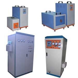
Gear Hardening Machine for Induction Gear Tooth and Surface Hardening
Gear Hardening Machine for Gear Tooth Surface Hardening | Engineering Selection Guide
Table of Contents
- Quick Answer
- What Is This Product?
- Key Applications
- Suitable Materials
- Working Principle
- Technical Specifications
- Recommended Model Selection
- Process Workflow
- Coil and Fixture Design
- Control System and Automation
- Common Problems and Solutions
- Engineering Selection Guide
- Advantages
- Limitations
- Why Choose HLQ Induction Equipment?
- FAQ
A gear hardening machine is an induction heat treatment system used to harden gear teeth, sprockets, ring gears, gear shafts, splines and transmission components. It rapidly heats the steel gear surface by electromagnetic induction and then quenches the heated layer to form a hard martensitic case while keeping the core tough. The machine is widely used in automotive, gearbox, reducer, mining machinery, agricultural equipment, construction machinery, bearing ring and power transmission industries. It solves common buyer problems such as low tooth wear resistance, unstable hardness, excessive distortion, slow outsourced heat treatment, inconsistent case depth and short gear service life.
Quick Answer
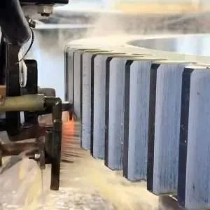
A gear hardening machine is a specialized induction hardening system designed to improve the surface hardness, wear resistance and fatigue strength of steel gears. It is best suited for medium carbon steel, alloy steel, carburized steel, sprockets, gear shafts, external gears, internal gears and large ring gears that require a hardened tooth surface with a tough core. Depending on gear size, module, tooth width and required hardening pattern, the machine can use spin hardening, single-shot hardening, tooth-by-tooth hardening, scanning hardening, contour hardening or dual-frequency hardening. In engineering practice, small and medium gears often use encircling or spin hardening, while large gears and high-precision tooth profiles often require tooth-by-tooth or contour hardening. Industry references commonly describe gear induction hardening as either encircling/spin hardening or tooth-to-tooth contour hardening. 
What Is This Product?
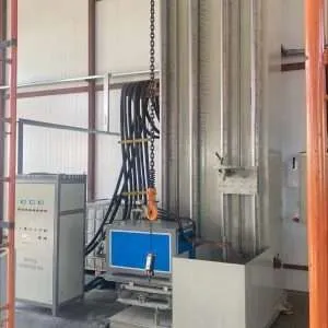
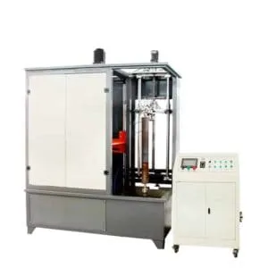
A gear hardening machine is a complete induction heat treatment system that heats and quenches selected working areas of gears. A typical system includes an induction power supply, matching transformer, CNC or PLC control system, rotary table, vertical or horizontal motion axis, gear clamping fixture, induction hardening coil, quenching spray device, quench tank, cooling water system, temperature monitoring unit and safety enclosure.
The main purpose of gear hardening is to create a hard surface layer on the tooth flank, tooth tip, tooth root or selected working area. This hardened layer improves resistance to wear, pitting, rolling contact fatigue and abrasive damage. At the same time, the gear core remains relatively tough, allowing the gear to absorb impact and bending stress during operation.
Compared with full furnace heat treatment, induction hardening is a fast and localized process. The gear is heated only where hardening is needed. The heating time is usually measured in seconds rather than hours. This can reduce energy consumption, decrease distortion, shorten production cycle time and make the process easier to automate.
However, gear hardening is more difficult than shaft hardening because the gear tooth has a complex profile. The tooth tip, tooth flank and tooth root do not heat at exactly the same rate. Magnetic field distribution, coil gap, rotation speed, quench delay and spray direction all affect the final hardened pattern. A reliable gear hardening machine must therefore be designed as a complete process system rather than as only a power supply.
Key Applications
Gear hardening machines are used in production lines and repair workshops where gears must work under heavy load, high contact stress, repeated impact or abrasive conditions. The equipment can be designed for small gears, medium gears, large gears, sprockets, ring gears, gear shafts and splined components.
| Application | Typical Workpiece | Hardening Method | Main Quality Target |
|---|---|---|---|
| Automotive transmission gears | Small spur gears, synchronizer gears, gear shafts | Single-shot, spin or scanning hardening | High repeatability, low distortion and stable hardness |
| Reducer and gearbox gears | Spur gears, helical gears, pinions | Spin hardening or scanning hardening | Wear resistance and controlled case depth |
| Large ring gears | External ring gears, internal ring gears, slewing rings | Tooth-by-tooth or scanning hardening | Uniform tooth surface hardening with limited distortion |
| Mining machinery gears | Large module gears and heavy-duty pinions | Tooth-by-tooth hardening | Deep hardened layer and high bending fatigue resistance |
| Agricultural machinery | Sprockets, drive gears, transmission wheels | Spin hardening or single-shot hardening | Cost-effective hardening and long service life |
| Construction machinery | Planet gears, gear rings, shaft gears | Scanning, tooth-by-tooth or contour hardening | Impact resistance, wear resistance and stable root hardness |
| Chain transmission | Sprockets and toothed wheels | Single-shot or spin hardening | Hard tooth profile and high productivity |
| Wind power and heavy equipment | Large gears, bearing rings, yaw and pitch components | Scanning or tooth-by-tooth hardening | Large diameter processing and process traceability |
Suitable Materials
Induction gear hardening is mainly used for steels that can transform to martensite after rapid heating and quenching. The most suitable materials are medium carbon steels and alloy steels. Low carbon steel can be difficult to harden directly unless it has been carburized, carbonitrided or otherwise carbon-enriched before induction hardening.
| Material Type | Typical Grades | Suitability | Engineering Notes |
|---|---|---|---|
| Medium carbon steel | C45, 1045, 45 steel, 50 steel | Very suitable | Common for sprockets, gears and shafts requiring direct surface hardening. |
| Alloy structural steel | 40Cr, 42CrMo, 4140, 4340, 34CrNiMo6 | Very suitable | Good hardenability; suitable for deeper case depth and heavy-duty gears. |
| Carburizing steel | 20CrMnTi, 8620, 18CrNiMo7-6 | Conditionally suitable | Can be induction hardened depending on carbon profile and required hardness pattern. |
| Ductile iron | QT500, QT600, nodular cast iron | Possible with process testing | Requires careful control to avoid cracking, local melting or unstable hardness. |
| Low carbon steel | 1018, Q235, mild steel | Not ideal directly | Usually cannot reach high hardness unless carburized or otherwise surface enriched. |
| Martensitic stainless steel | 410, 420 and similar grades | Special application | Requires grade-specific heating and tempering procedure. |
Material Selection Reference
| Gear Requirement | Preferred Material Group | Reason |
|---|---|---|
| General wear resistance | Medium carbon steel | Economical and easy to induction harden. |
| Heavy load and deeper case | Alloy steel | Better hardenability and stronger core strength. |
| High precision transmission | Carburized alloy steel | Good surface fatigue performance when processed correctly. |
| Shock and impact load | 42CrMo / 4140 / 34CrNiMo6 type steels | Good balance between hardened surface and tough core. |
Working Principle
The gear hardening machine works by electromagnetic induction. Alternating current from the induction power supply flows through a copper induction coil. The coil creates a rapidly changing magnetic field. When the gear is placed in this field, eddy currents are induced in the gear surface. These eddy currents produce heat due to the electrical resistance of the steel.
The heating depth is related to frequency, material magnetic properties, power density and heating time. In general, lower frequency provides deeper heating, while higher frequency concentrates heat closer to the surface. Recent gear heat treatment guidance also notes that lower frequency produces deeper case depth, and that tooth-by-tooth hardening is usually reserved for large gears or sprockets that are not practical for single-shot hardening due to power limits.
After the required surface temperature is reached, quenching medium is applied immediately. The rapid cooling transforms the heated surface layer into martensite. This martensitic layer gives the gear high hardness and improved wear resistance. A tempering operation is often added after hardening to reduce brittleness and stabilize the microstructure.
| Process Stage | What Happens | Key Control Parameter |
|---|---|---|
| Gear positioning | Gear is clamped on a mandrel, rotary table or indexing fixture | Runout, tooth alignment, fixture rigidity |
| Induction heating | Gear surface is heated by induced current | Power, frequency, heating time, coil gap |
| Heat penetration | Heat reaches the required effective case depth | Frequency, power density, scan speed |
| Quenching | Water, polymer or oil cools the heated surface rapidly | Flow rate, pressure, concentration, delay time |
| Martensite formation | Surface transforms into a hardened structure | Cooling rate and steel hardenability |
| Tempering | Hardness is stabilized and brittleness is reduced | Tempering temperature and time |
| Inspection | Hardness, case depth and distortion are measured | HRC, ECD, runout, microstructure |
Technical Specifications
| Parameter | Specification | Notes |
|---|---|---|
| Product name | Gear Hardening Machine | For gears, sprockets, ring gears, gear shafts and splines |
| Heating method | Electromagnetic induction heating | Fast, localized and controllable surface heating |
| Power range | 30kW-1000kW or customized | Large single-shot gear hardening may require higher power |
| Frequency range | 1kHz-200kHz | Selected according to gear size, module and case depth |
| Gear diameter range | 20mm-3000mm or customized | Machine structure depends on gear size and loading method |
| Gear width | 5mm-500mm or customized | Wide gears may require scanning or special quench design |
| Gear types | Spur gear, helical gear, sprocket, ring gear, internal gear, gear shaft | Coil and fixture must match gear geometry |
| Hardening methods | Single-shot, spin, scanning, tooth-by-tooth, contour, dual-frequency | Selected by gear size, module, quality target and output |
| Typical hardness | HRC 50-62 depending on material | Final hardness depends on carbon content and quenching condition |
| Typical effective case depth | 0.8-8mm or customized | Deeper case generally requires lower frequency and longer heating time |
| Quenching medium | Water, polymer solution, oil or special quench liquid | Polymer solution is commonly used to reduce cracking risk |
| Motion control | Manual, semi-automatic, PLC or CNC control | CNC control is recommended for precision gear production |
| Cooling system | Closed-loop water cooling or industrial chiller | Required for power supply, transformer and coil |
| Optional functions | Automatic loading, recipe storage, pyrometer feedback, data recording | Recommended for mass production and traceability |
 Typical Process Parameter Window
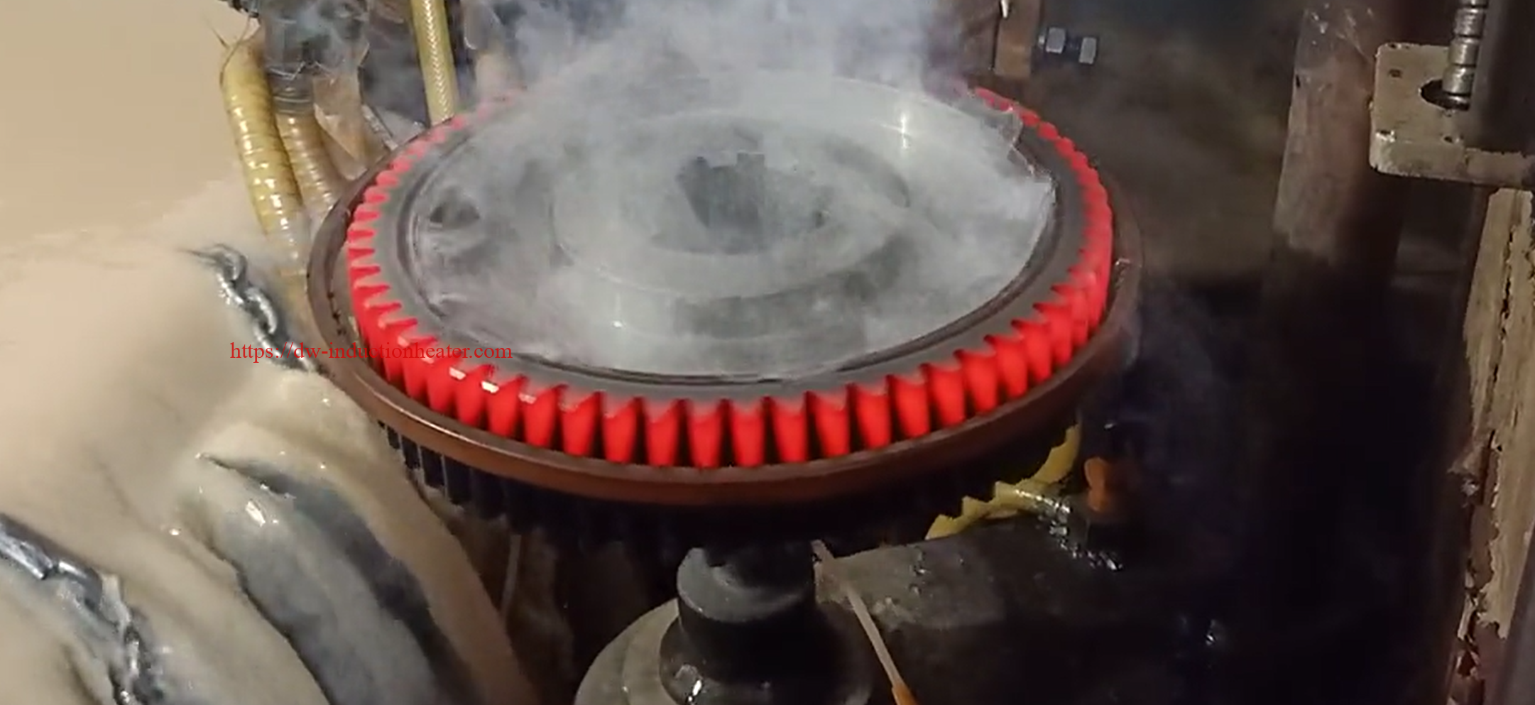
| Gear Category | Typical Case Depth | Typical Hardness | Common Process Method |
|---|---|---|---|
| Small sprocket | 0.8-2.0mm | HRC 50-58 | Single-shot or spin hardening |
| Automotive gear | 1.0-2.5mm | HRC 58-62 | Single-shot, scanning or dual-frequency |
| Reducer gear | 1.5-4.0mm | HRC 52-60 | Spin or scanning hardening |
| Large ring gear | 3.0-8.0mm | HRC 50-58 | Tooth-by-tooth or contour hardening |
| Gear shaft / spline | 1.5-5.0mm | HRC 50-60 | Scanning hardening |
Recommended Model Selection
| Application | Material | Recommended Power | Frequency |
|---|---|---|---|
| Small sprocket hardening | 45 steel, C45, 40Cr | 30-80kW | 30-100kHz |
| Small spur gear hardening | 1045, 4140, 40Cr | 50-120kW | 20-80kHz |
| Medium gearbox gear hardening | 40Cr, 42CrMo, 4140 | 100-250kW | 8-30kHz |
| Gear shaft and spline hardening | 42CrMo, 40CrNiMo, 4140 | 100-300kW | 5-20kHz |
| Large gear tooth-by-tooth hardening | 42CrMo, 34CrNiMo6, forged alloy steel | 160-500kW | 3-15kHz |
| Large ring gear contour hardening | Alloy steel, forged steel | 250-800kW | 1-10kHz |
| High productivity single-shot hardening | Medium carbon steel or alloy steel | 300-1000kW or higher | 1-30kHz |
Hardening Method Selection Chart
| Hardening Method | Best For | Main Benefit | Limitation |
|---|---|---|---|
| Spin hardening | Small and medium external gears, sprockets | Simple structure and high productivity | Root pattern may be harder to control on large-module gears |
| Single-shot hardening | High-volume gears with stable geometry | Very short cycle time | Requires high power and precise coil design |
| Tooth-by-tooth hardening | Large gears, large sprockets and high module gears | Good local control and lower total power requirement | Slower cycle time |
| Scanning hardening | Gear shafts, splines and wide gear faces | Good for long or wide components | Requires accurate CNC motion |
| Contour hardening | Precision gears needing root and flank control | Better hardened pattern following tooth shape | Complex coil and process development |
| Dual-frequency hardening | Gears needing both root and flank/tip hardening | Improves temperature distribution across tooth geometry | Higher investment and process complexity |
Dual-frequency induction hardening is used because gear tooth roots and tooth tips often require different heating behavior. Low frequency helps heat deeper areas such as tooth roots, while high frequency concentrates heat on flanks and tips; this is why dual-frequency concepts are often used for contour-like gear hardening patterns.
Process Workflow
A stable gear hardening result starts before heating. Gear material, machining condition, prior heat treatment, surface cleanliness and tooth geometry must be confirmed before the process recipe is selected. The machine then controls positioning, heating, quenching, tempering and inspection.
| Step | Operation | Engineering Control Point | Quality Risk if Ignored |
|---|---|---|---|
| 1 | Confirm gear drawing and material | Module, tooth number, diameter, steel grade, hardness target | Wrong case depth or hardness |
| 2 | Check prior heat treatment | Normalize, quench-temper, carburize or pre-harden condition | Unstable hardness and cracking |
| 3 | Clean gear surface | Remove oil, rust, chips and oxide scale | Uneven heating or quench spots |
| 4 | Load gear on fixture | Check concentricity, runout and alignment | Uneven hardened layer |
| 5 | Select process recipe | Power, frequency, heating time, scan speed, quench delay | Overheating, underheating or cracking |
| 6 | Induction heating | Control coil gap and temperature rise | Tip overheating or root underheating |
| 7 | Immediate quenching | Control spray angle, flow, pressure and medium concentration | Soft spots, cracks or distortion |
| 8 | Tempering | Reduce brittleness and stabilize structure | Excessive brittleness or cracking in service |
| 9 | Inspection | Hardness, case depth, microstructure, runout | Unqualified gear performance |
Process Flow Chart
Gear Drawing Review → Material Confirmation → Surface Cleaning → Fixture Loading → Coil Positioning → Recipe Selection → Induction Heating → Immediate Quenching → Tempering → Hardness Test → Case Depth Inspection → Runout Measurement → Final Approval
Coil and Fixture Design
The induction coil and fixture are the most important parts of a gear hardening machine. A good power supply cannot produce a good gear if the coil is poorly designed. For gear hardening, the coil must match tooth shape, module, root radius, pitch diameter, gear width and required hardening pattern.
| Coil Type | Application | Design Features | Engineering Notes |
|---|---|---|---|
| Encircling coil | Spin hardening and single-shot hardening | Surrounds the entire gear outside diameter | Fast cycle; requires high power and uniform gear rotation |
| Tooth-by-tooth inductor | Large module gears and ring gears | Heats one tooth or tooth gap at a time | Good for large gears where a full encircling coil is impractical |
| Scanning coil | Gear shafts, splines and wide gear faces | Moves along gear width or shaft length | Requires accurate CNC motion and quench tracking |
| Contour coil | Precision gear tooth profile | Designed to follow tooth profile and root area | Useful when root hardening pattern must be controlled |
| Dual-frequency coil system | Advanced gear contour hardening | Uses low and high frequency heating behavior | Improves heat distribution but increases system complexity |
 Fixture Design Requirements

| Fixture Item | Requirement | Reason |
|---|---|---|
| Gear clamping | Rigid, repeatable and centered | Prevents uneven coil gap and hardening variation |
| Rotation system | Stable speed with low runout | Ensures uniform circumferential heating |
| Indexing system | Accurate tooth positioning | Required for tooth-by-tooth hardening |
| Quench collection | Proper drainage and filtration | Maintains clean quench medium and safe work area |
| Changeover design | Quick adjustment for different gears | Reduces downtime in multi-product production |
Quenching Design Options
Quenching can be performed by submerging the gear, using an integrated spray quench, or using a separate spray ring below the inductor. These approaches are widely used in gear spin hardening applications, with the best choice depending on gear size, cycle time and distortion control.
| Quenching Method | Best Application | Main Benefit | Design Concern |
|---|---|---|---|
| Integrated spray quench | Small and medium gears | Short delay between heating and cooling | Nozzle blockage and spray uniformity |
| Separate quench ring | Spin hardening systems | Stable circumferential cooling | Alignment with gear and coil position |
| Submerged quenching | Large gears and some tooth-by-tooth methods | Strong cooling and less temper-back risk | Requires higher heating power and controlled tank temperature |
| Polymer spray quench | Crack-sensitive alloy steels | Adjustable cooling severity | Requires concentration and temperature control |
Control System and Automation
A modern gear hardening machine should be controlled by PLC or CNC, especially when the gear requires stable case depth and repeatable hardening pattern. Automation is important because small changes in coil gap, power, time, rotation speed or quench delay can significantly change final hardness.
| Control Function | Description | Benefit |
|---|---|---|
| Recipe management | Stores power, time, frequency, rotation speed and quench parameters | Improves repeatability for different gear models |
| CNC motion control | Controls vertical scanning, rotary table and indexing | Ensures accurate gear positioning |
| Power monitoring | Displays voltage, current, power and frequency | Helps diagnose heating stability |
| Temperature monitoring | Uses infrared pyrometer or thermal feedback when applicable | Reduces overheating and process drift |
| Quench control | Controls pressure, flow, concentration and delay | Improves hardness and reduces crack risk |
| Fault protection | Overcurrent, overvoltage, low water flow and overheating alarms | Protects machine and operator |
| Data recording | Records batch number, process recipe and alarm history | Supports quality traceability |
Quality Inspection Chart
| Inspection Item | Typical Method | Purpose | Common Acceptance Focus |
|---|---|---|---|
| Surface hardness | Rockwell hardness test | Confirms martensitic hardening result | HRC range according to drawing |
| Effective case depth | Section cutting and hardness traverse | Confirms load-bearing hardened layer | Depth at specified hardness limit |
| Hardening pattern | Etching or macro inspection | Confirms tooth flank, tip and root coverage | No missing root or over-burned tip |
| Microstructure | Metallographic inspection | Checks martensite, retained austenite and overheating | No excessive grain growth or local melting |
| Crack inspection | Magnetic particle or dye penetrant testing | Detects quench cracks | No tooth root or flank cracks |
| Distortion | Runout, pitch and gear measurement | Confirms dimensional stability | Within machining or assembly tolerance |
Common Problems and Solutions
| Problem | Possible Cause | Engineering Solution |
|---|---|---|
| Tooth tip overheated | Coil too close to tip, power too high, heating time too long | Adjust coil profile, reduce power or optimize heating time |
| Tooth root too soft | Insufficient magnetic field at root, wrong coil design or frequency too high | Use contour coil, lower frequency or dual-frequency process |
| Uneven hardness around gear | Gear runout, unstable rotation or uneven coil gap | Improve fixture concentricity and rotary accuracy |
| Cracks after hardening | Too severe quenching, high carbon steel, sharp root radius or overheating | Use polymer quench, reduce quench severity and optimize heating temperature |
| Excessive distortion | Uneven heating, poor clamping, unsuitable quenching direction | Balance heating pattern, improve fixture and optimize quench spray |
| Case depth too shallow | Frequency too high, heating time too short or power too low | Lower frequency, increase heating time or increase power |
| Case depth too deep | Frequency too low, heating time too long or excessive power | Increase frequency, reduce heating time or lower power |
| Soft spots | Poor quench coverage, blocked spray holes or oil on surface | Clean gear, check spray nozzles and improve quench flow |
| Coil overheating | Low cooling water flow, scale blockage or overload | Use treated cooling water and install flow/temperature protection |
| Temper-back on adjacent tooth | Heat spreads to previously hardened tooth during tooth-by-tooth hardening | Improve cooling strategy and use controlled tooth indexing sequence |
 Engineering Selection Guide

Selecting a gear hardening machine requires more than choosing power. Gear size, module, tooth width, material, required hardness pattern, case depth, production volume and inspection standard all affect machine configuration.
1. Define the Gear Geometry
| Gear Parameter | Why It Matters | Selection Impact |
|---|---|---|
| Outside diameter | Determines machine stroke, rotary table and coil size | Large gears may require tooth-by-tooth hardening |
| Module / DP | Affects tooth size and root heating difficulty | Large module gears need special coil design |
| Tooth width | Determines scan length and coil height | Wide gears may need scanning or multi-turn coil |
| Internal or external gear | Changes coil access and quench direction | Internal gears often require special inductors |
| Helical angle | Influences heating uniformity along tooth direction | May require helical tracking or special coil shape |
2. Confirm Material and Hardness Target
The steel grade determines whether the gear can reach the required hardness. For direct induction hardening, medium carbon and alloy steels are preferred. Low carbon steels usually require carburizing before hardening.
3. Select Case Depth and Frequency
| Required Case Depth | Typical Frequency Range | Typical Application |
|---|---|---|
| 0.8-1.5mm | 30-100kHz | Small gears and sprockets |
| 1.5-3mm | 10-30kHz | Medium gears and gearbox parts |
| 3-5mm | 3-10kHz | Heavy-duty gears and gear shafts |
| 5-8mm | 1-5kHz | Large module gears and mining gears |
4. Choose the Right Hardening Method
| Production Situation | Recommended Method | Reason |
|---|---|---|
| Small gears, high output, simple profile | Single-shot or spin hardening | Fast cycle and good productivity |
| Large diameter gear with limited power availability | Tooth-by-tooth hardening | Requires less instantaneous power than full-gear heating |
| Gear shaft or long spline | Scanning hardening | Good control along length |
| Precision tooth root and flank pattern | Contour or dual-frequency hardening | Better control of tooth profile heating |
5. Confirm Quenching System
Quenching is as important as heating. The spray ring must cover the tooth flank, tip and root uniformly. For gears with crack sensitivity, polymer quench is often preferred because quench severity can be adjusted by concentration, pressure and temperature.
6. Prepare the Information for Quotation
| Information Needed | Example | Why It Is Needed |
|---|---|---|
| Gear drawing | PDF, CAD, diameter, module, tooth width | For machine stroke, fixture and coil design |
| Material grade | 40Cr, 42CrMo, 4140, 20CrMnTi | For hardness and quenching evaluation |
| Required hardness | HRC 52-58, HRC 58-62 | For process temperature and quenching selection |
| Required case depth | 1.5mm, 3mm, 5mm | For frequency and power selection |
| Hardening area | Tooth flank, root, full tooth, spline | For coil geometry and quench design |
| Production quantity | Pieces per hour or pieces per day | For automation level and loading method |
Advantages
| Advantage | Engineering Meaning | Buyer Benefit |
|---|---|---|
| Localized hardening | Only the required tooth surface is heated | Lower distortion than full furnace heating |
| Fast cycle time | Heating time is usually seconds, not hours | Higher productivity and lower work-in-process inventory |
| Good wear resistance | Creates hard martensitic surface layer | Longer gear service life |
| Tough core retained | Core is not fully hardened in many processes | Better impact resistance |
| Easy automation | Power, motion and quench can be controlled by CNC/PLC | Consistent quality in mass production |
| Clean process | No open flame and no furnace atmosphere required for many applications | Improved workshop environment |
| Flexible production | Recipe and fixture changes allow different gear models | Suitable for multiple product batches |
Limitations
| Limitation | Explanation | Recommended Solution |
|---|---|---|
| Coil design is critical | A standard coil may not produce the required tooth pattern | Design coil according to gear drawing and hardening pattern |
| Not every steel is suitable | Low carbon steel cannot reach high hardness without carbon enrichment | Use medium carbon/alloy steel or carburized steel |
| Crack risk exists | Sharp tooth roots, high carbon and severe quenching can cause cracks | Optimize quench medium, preheat condition and heating curve |
| Large gears need complex equipment | Large ring gears require strong fixture and accurate indexing | Use CNC tooth-by-tooth or scanning hardening system |
| Process development is required | Hardness pattern depends on many interacting variables | Perform sample testing before mass production |
| Inspection is essential | Surface hardness alone cannot confirm a good gear | Check case depth, pattern, cracks and distortion |
Why Choose HLQ Induction Equipment?
HLQ Induction Equipment provides engineering-oriented induction hardening solutions for gears, sprockets, shafts, rings and other transmission components. For gear hardening applications, HLQ focuses on the complete process result, including hardened pattern, case depth, surface hardness, tooth root condition, quenching uniformity, distortion control and production efficiency.
| HLQ Capability | Customer Value |
|---|---|
| Customized machine design | Machine structure can be designed for small gears, large gears, ring gears and gear shafts. |
| Power and frequency selection | Helps match required case depth, gear size and production rate. |
| Induction coil engineering | Customized coils improve heating uniformity and hardening pattern control. |
| CNC motion and fixture support | Improves repeatability for rotation, scanning and tooth-by-tooth indexing. |
| Integrated quenching system | Spray design supports stable hardness and reduced crack risk. |
| Process testing support | Helps customers optimize power, time, speed and quenching parameters. |
| Industrial control system | PLC/CNC recipe management supports repeatable production and quality tracking. |
For a correct gear hardening proposal, HLQ recommends that customers provide the gear drawing, material grade, outside diameter, tooth width, module, number of teeth, required surface hardness, effective case depth, hardening area, production quantity and available factory power supply. With these details, HLQ can recommend the proper machine power, frequency, coil type, fixture structure, quenching method and automation level.
FAQ
1. What is a gear hardening machine?
A gear hardening machine is an induction heat treatment system that heats the surface of gear teeth and then quenches them to form a hard wear-resistant layer. It is used to improve gear service life, contact fatigue strength and surface wear resistance.
2. Which gears can be induction hardened?
Spur gears, helical gears, sprockets, ring gears, internal gears, gear shafts and splines can be induction hardened if the material and geometry are suitable. The coil and fixture must be designed according to the gear shape.
3. What materials are suitable for gear induction hardening?
Medium carbon steel and alloy steel are most suitable. Common examples include 45 steel, C45, 1045, 40Cr, 42CrMo, 4140 and similar grades. Low carbon steel usually requires carburizing before it can achieve high surface hardness.
4. What hardness can be achieved?
Many steel gears can reach approximately HRC 50-62 after induction hardening, depending on carbon content, alloy composition, prior microstructure, heating temperature, quenching medium and tempering process.
5. What is the difference between spin hardening and tooth-by-tooth hardening?
Spin hardening uses an encircling inductor while the gear rotates, making it efficient for small and medium gears. Tooth-by-tooth hardening heats individual teeth or tooth gaps one at a time, making it useful for large gears, large sprockets and more precise local control. Tooth-by-tooth hardening is slower but can be more suitable for large gears that cannot be single-shot hardened economically.
6. Does induction hardening reduce gear distortion?
Induction hardening often produces lower distortion than full furnace heating because it heats only the required surface layer for a short time. However, distortion can still occur if heating, clamping or quenching is not balanced.
7. What frequency should be used for gear hardening?
Frequency depends on required case depth and gear size. Small gears and shallow case depths often use higher frequency, while large gears and deeper case depths require lower frequency. Final selection should be based on sample testing and gear drawing.
8. Why is the tooth root difficult to harden?
The tooth root has different geometry and magnetic field distribution from the tooth tip and flank. It may receive less energy during simple high-frequency heating. Lower frequency, contour coils, dual-frequency heating or tooth-by-tooth methods may be used to improve root hardening.
9. What information is needed for a quotation?
Please provide gear drawing, material grade, outside diameter, bore size, gear width, module, number of teeth, hardening area, required hardness, required case depth, production quantity, available voltage and whether automatic loading is required.
10. Can HLQ provide a complete gear hardening system?
Yes. HLQ can provide the induction power supply, CNC hardening machine, gear fixture, induction coil, quenching system, cooling water system, control cabinet and process support according to the gear hardening requirement.