
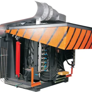

Electric Melting Induction Furance
Electric Melting Induction Furnace for Industrial Steel and Nonferrous Foundries
What Is the Electric Induction Melting Furnace?
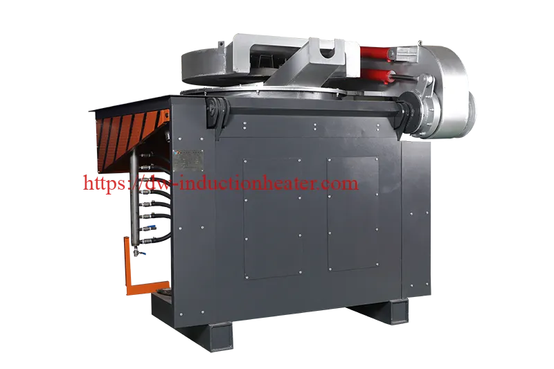
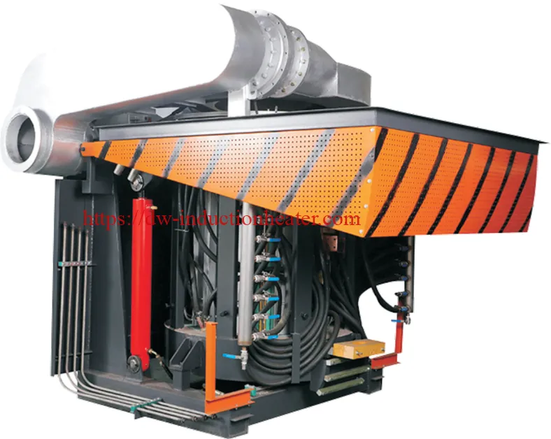
The HLQ KGPS Electric Induction Melting Furnace is an intermediate-frequency, SCR/thyristor-controlled coreless induction furnace system for batch melting of steel, cast iron, copper, aluminum and compatible alloys. The published product range covers nine furnace charge classes from 10–50kg to 1500kg, rated power classes from 50–1000kW, and operating frequencies of 0.8–2.5kHz. It is designed for industrial foundries requiring a matched power converter, capacitor bank, refractory-lined furnace, cooling system and pouring arrangement. Rated charge capacity is measured in kilograms per batch, not kilograms per hour. Actual melting efficiency, production output and electrical performance must be validated under defined operating conditions.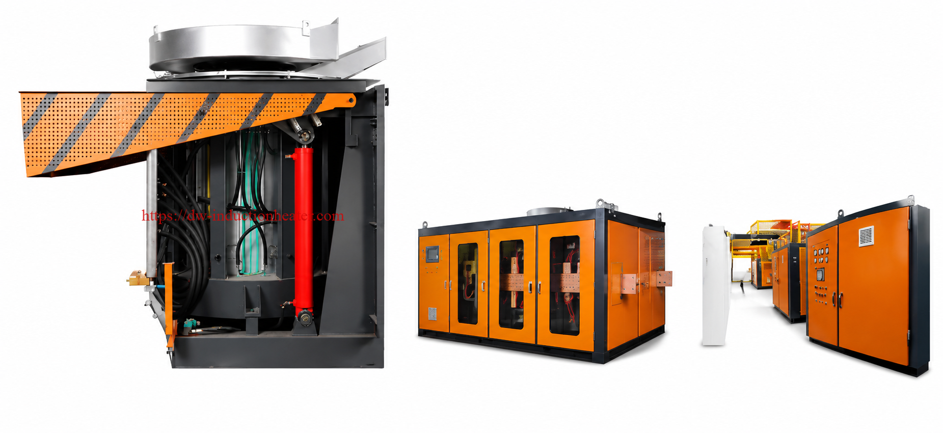
Quick Answer: Product Overview
| Parameter | Engineering Description |
|---|---|
| Product Name | Electric Induction Melting Furnace |
| Power Supply Technology | KGPS / SCR / Thyristor |
| Induction Heating Type | Intermediate-Frequency Coreless Induction Melting |
| Rated Capacity | 10–1500kg |
| Published Rated Power | 50–1000kW |
| Published Operating Frequency | 0.8–2.5kHz |
| Suitable Materials | Steel, Cast Iron, Copper, Aluminum and Compatible Alloys |
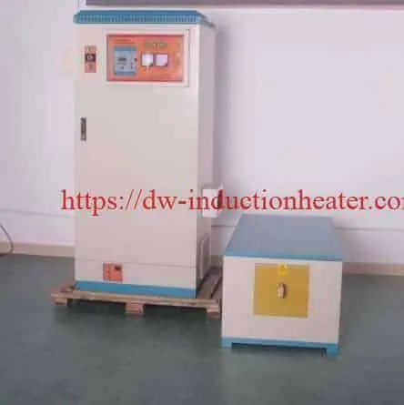
| Major Components | KGPS Power Supply, Capacitor Cabinet, Furnace Body, Induction Coil and Cooling System |
| Primary Application | Industrial Foundry Melting and Metal Casting |
For a detailed comparison of electrical power converters, explore HLQ’s
KGPS induction generator power supplies.
Key Applications
Industrial electric induction melting furnaces convert electrical energy into heat inside conductive metal. Their applications include steel casting, iron foundries, nonferrous alloy production and metal recycling.
Industrial Application Comparison
| Application | Typical Material | Production Objective | Critical Requirement |
|---|---|---|---|
| Steel Casting Foundry | Carbon Steel and Alloy Steel | Controlled Melting and Pouring | Temperature, Chemistry and Refractory Life |
| Cast Iron Foundry | Gray Iron and Ductile Iron Feedstock | Batch Iron Melting | Carbon, Silicon and Melt Quality |
| Stainless Steel Melting | Stainless Steel Alloys | Alloy Production | Composition and Oxidation Control |
| Copper Casting | Copper and Copper Alloys | Nonferrous Melting | Oxidation and Crucible Compatibility |
| Brass and Bronze Production | Brass and Bronze Alloys | Alloy Casting | Alloy Composition and Fume Management |
| Aluminum Recycling | Aluminum Ingots and Clean Scrap | Metal Recovery | Dross, Moisture and Oxide Control |
| Special Alloy Production | Selected Industrial Alloys | Controlled Batch Melting | Material-Specific Furnace Configuration |
Typical Foundry Process Requirements
| Application | Important Process Variable | Acceptance Method |
|---|---|---|
| Steel Melting | Tapping Temperature | Temperature and Chemical Analysis |
| Cast Iron Melting | Carbon and Silicon Content | Composition and Foundry Quality Testing |
| Copper Melting | Oxidation and Melt Temperature | Metal Quality and Yield Measurement |
| Aluminum Melting | Dross Formation | Accepted Metal Yield |
| Industrial Batch Melting | Electrical Consumption | Measured kWh/t |
For ferrous metal applications, see HLQ’s
induction furnaces for melting iron and steel.
Suitable Materials
Induction melting efficiency depends on the electromagnetic and thermal properties of the charge, including electrical resistivity, magnetic permeability, thermal conductivity, density and melting enthalpy.
Material Compatibility
| Material | Melting Characteristics | Engineering Consideration |
|---|---|---|
| Carbon Steel | High-Temperature Ferrous Melting | Refractory and Slag Compatibility |
| Cast Iron | Carbon- and Silicon-Dependent Melting Range | Chemical Composition Control |
| Stainless Steel | High-Temperature Alloy Melting | Alloy Retention and Refractory Selection |
| Copper | Pure Copper Melting Point Approximately 1085°C | High Electrical Conductivity and Oxidation |
| Brass | Composition-Dependent Melting Range | Zinc Fumes and Alloy Loss |
| Bronze | Composition-Dependent Melting Range | Alloying Element Control |
| Aluminum | Pure Aluminum Melting Point Approximately 660°C | Dross, Oxide Film and Metal Cleanliness |
Material Properties Affecting Induction Melting
| Property | Effect on the Process | Design Response |
|---|---|---|
| Electrical Resistivity | Affects Eddy-Current Heating | Appropriate Frequency and Coil Matching |
| Magnetic Permeability | Changes Electromagnetic Coupling | Account for Temperature-Dependent Properties |
| Melting Enthalpy | Determines Useful Thermal Energy | Metal-Specific Energy Calculation |
| Density | Changes Metal Mass per Furnace Volume | Correct Crucible and Freeboard Design |
| Oxidation | Influences Metal Loss and Casting Quality | Temperature and Atmosphere Control |
For larger copper melting applications, explore HLQ’s
induction copper melting furnace solutions.
Working Principle
The KGPS induction melting system uses SCR-controlled power electronics to generate intermediate-frequency alternating current.
Alternating current passes through a water-cooled copper induction coil surrounding the melting chamber.
The resulting alternating magnetic field induces eddy currents within conductive metal. Electrical resistance converts these currents into heat, progressively melting the charge.
Electromagnetic forces can also produce circulation within the molten bath, depending on the furnace construction and operating conditions.
Figure 1. KGPS Induction Melting Furnace Working Principle
         THREE-PHASE AC POWER
                  |
                  v
       +---------------------+
       | SCR RECTIFIER       |
       +---------------------+
                  |
                  v
       +---------------------+
       | DC LINK / REACTOR   |
       +---------------------+
                  |
                  v
       +---------------------+
       | THYRISTOR INVERTER  |
       +---------------------+
                  |
                  v
       +---------------------+
       | COMPENSATION        |
       | CAPACITOR BANK      |
       +---------------------+
                  |
                  v
       +---------------------+
       | WATER-COOLED        |
       | INDUCTION COIL      |
       +---------------------+
                  |
                  v
        ALTERNATING MAGNETIC
                FIELD
                  |
                  v
       +---------------------+
       | REFRACTORY-LINED    |
       | METAL CHARGE        |
       +---------------------+
                  |
                  v
           EDDY CURRENTS
                  |
                  v
         HEAT GENERATION
                  |
                  v
         COMPLETE MELTING
                  |
                  v
       TEMPERATURE / CHEMISTRY
                  |
                  v
           SAFE POURING


Working Principle by Component
| Component | Function | Critical Requirement |
|---|---|---|
| SCR Rectifier | Controls Conversion of AC Input Power | Electrical Protection |
| Thyristor Inverter | Produces Intermediate-Frequency Power | Stable Resonant Operation |
| Capacitor Bank | Provides Electrical Compensation | Correct Voltage and Current Ratings |
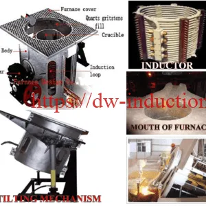
| Induction Coil | Generates Alternating Magnetic Field | Cooling and Electrical Insulation |
| Furnace Lining | Contains High-Temperature Metal | Thermal and Chemical Resistance |
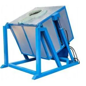
| Tilting Mechanism | Transfers Molten Metal | Mechanical Safety and Stability |
Technical Specifications
The following specifications are based on the original HLQ product information. Rated power, electrical consumption and melting time should be confirmed during factory testing.
General Technical Specifications
| Parameter | Specification | Notes |
|---|---|---|
| Product | Electric Induction Melting Furnace | KGPS Intermediate-Frequency Series |
| Power Supply Technology | SCR / Thyristor | KGPS Configuration |
| Published Rated Capacity | 10–1500kg | 9 Furnace Capacity Classes |
| Published Rated Power | 50–1000kW | Rated Power Definition Requires Verification |
| Operating Frequency | 0.8–2.5kHz | Depends on Furnace Capacity |
| Transformer Capacity | 60–1500kVA | Published Model-Dependent Values |
| Published Output Voltage | 750–2500V | Not the Incoming Plant Voltage |
| Published Cooling Water Flow | 3–25t/h | Model Dependent |
| Power Regulation | SCR-Controlled | Operating Range to Be Confirmed |
| Furnace Shell | Aluminum or Steel Configuration | Subject to Equipment Selection |
| Pouring Arrangement | Hydraulic / Mechanical Tilting | Confirm Full Scope of Supply |
| Additional Automation | Temperature Feedback and PLC/HMI Options | Optional Configuration |
KGPS Furnace Capacity and Electrical Parameters
| Capacity | Rated Power | Transformer | Output Voltage | Frequency | Cooling Water |
|---|---|---|---|---|---|
| 10–50kg | 50kW | 60kVA | 750V | 2.5kHz | 3t/h |
| 100kg | 100kW | 120kVA | 750V | 1kHz | 5t/h |
| 150kg | 100kW | 120kVA | 750V | 1kHz | 5t/h |
| 250kg | 130kW | 150kVA | 750V | 1kHz | 7t/h |
| 350kg | 180kW | 200kVA | 750V | 1kHz | 8t/h |
| 500kg | 250kW | 315kVA | 750V | 1kHz | 10t/h |
| 750kg | 450kW | 500kVA | 1500V | 1kHz | 15t/h |
| 1000kg | 600kW | 800kVA | 2500V | 0.8kHz | 18t/h |
| 1500kg | 1000kW | 1500kVA | 2500V | 0.8kHz | 25t/h |
Electrical clarification: The original page uses the input-voltage label “380-2” for the 1000kg and 1500kg configurations. This entry must be clarified by the manufacturer. It should not be interpreted as a confirmed electrical supply specification.
Published Electrical Energy Consumption
| Capacity | Steel kWh/t | Cast Iron kWh/t | Copper kWh/t | Aluminum kWh/t | Published Time |
|---|---|---|---|---|---|
| 10–50kg | 900 | 850 | 500 | 780 | 20–60min |
| 100kg | 850 | 800 | 500 | 750 | 20–60min |
| 150kg | 850 | 800 | 500 | 750 | 30–70min |
| 250kg | 800 | 750 | 490 | 710 | 30–70min |
| 350kg | 750 | 700 | 480 | 670 | 30–70min |
| 500kg | 700 | 650 | 480 | 620 | 30–70min |
| 750kg | 650 | 630 | 400 | 600 | 40–80min |
| 1000kg | 620 | 610 | 390 | 570 | 50–90min |
| 1500kg | 600 | 580 | 380 | 540 | 50–90min |
The electrical consumption and melting-time values above are published reference data. They do not establish guaranteed performance under identical cold-start conditions, tapping temperatures or electrical measurement boundaries.
Recommended Model Selection
The recommended induction furnace should be selected according to metal grade, charge weight, temperature, required production rate, electrical supply, cooling and refractory requirements.
Recommended Furnace Capacity Selection
| Application | Material | Recommended Power | Frequency |
|---|---|---|---|
| 10–50kg Batch Melting | Steel / Cast Iron / Qualified Nonferrous Metals | 50kW Catalog Class | 2.5kHz |
| 100kg Batch Melting | Steel / Cast Iron | 100kW Catalog Class | 1kHz |
| 150kg Batch Melting | Steel / Cast Iron | 100kW Catalog Class; Melting Time Requires Verification | 1kHz |
| 250kg Batch Melting | Steel / Cast Iron | 130kW Catalog Class; Melting Time Requires Verification | 1kHz |
| 350kg Batch Melting | Steel / Cast Iron | 180kW Catalog Class; Melting Time Requires Verification | 1kHz |
| 500kg Batch Melting | Steel / Cast Iron | 250kW Catalog Class; Melting Time Requires Verification | 1kHz |
| 750kg Batch Melting | Steel / Cast Iron | 450kW Catalog Class | 1kHz |
| 1000kg Batch Melting | Steel / Cast Iron | 600kW Catalog Class | 0.8kHz |
| 1500kg Batch Melting | Steel / Cast Iron | 1000kW Catalog Class | 0.8kHz |
These are the published KGPS furnace classes, not independently validated production recommendations. Final power selection requires measured real input power, actual metal temperature and melt-cycle verification.
Customer Model Selection Checklist
| Selection Factor | Required Data |
|---|---|
| Metal Grade | Exact Alloy and Composition |
| Charge Weight | kg per Batch |
| Production Capacity | Accepted kg/h or t/h |
| Melting Temperature | Required Tapping Temperature |
| Electrical Supply | Voltage, Frequency and Transformer Capacity |
| Cooling System | Water Flow, Temperature, Quality and Pressure |
| Furnace Structure | Shell Type, Lining and Tilting Requirement |
| Performance | Measured kWh/t and Tap-to-Tap Cycle |
For aluminum production, compare HLQ’s
induction aluminum melting furnace equipment.
Process Workflow
An industrial melting process should follow a documented procedure covering material inspection, furnace preparation, controlled induction heating, melt analysis and safe pouring.
Figure 2. Industrial Induction Melting Workflow
      MATERIAL IDENTIFICATION
                |
                v
       CLEAN AND DRY CHARGE
                |
                v
     REFRACTORY LINING CHECK
                |
                v
    COOLING AND SAFETY CHECK
                |
                v
        CONTROLLED CHARGING
                |
                v
      START INDUCTION MELTING
                |
                v
      ELECTRICAL MONITORING
                |
                v
     MELT TEMPERATURE CONTROL
                |
                v
       METAL CHEMISTRY CHECK
                |
                v
       PREPARE DRY LADLE
                |
                v
       CONTROLLED POURING
                |
                v
       RECORD PRODUCTION
                |
                v
        FURNACE INSPECTION

Production Quality Control
| Process Stage | Inspection | Required Record |
|---|---|---|
| Material Charging | Metal Grade, Weight and Dryness | Charge Record |
| Furnace Preparation | Refractory and Cooling System | Inspection Checklist |
| Electrical Heating | Real Power and Frequency | Power and Time Record |
| Complete Melting | Temperature and Chemistry | Melting Quality Record |
| Pouring | Safe Ladle and Tilting Operation | Pouring Record |
| Production Analysis | kg, kWh and Cycle Time | Energy and Productivity Report |
Coil and Fixture Design
The induction coil, refractory lining and furnace structure must be designed as an integrated system. Coil turns, copper conductor dimensions, compensation capacitance and cooling arrangements depend on the metal charge and resonant electrical conditions.
Induction Coil Design Requirements
| Component | Design Requirement | Potential Risk |
|---|---|---|
| Copper Induction Coil | Appropriate Turns, Conductor Size and Cooling | Electrical Short or Overheating |
| Coil Insulation | Correct Electrical and Thermal Insulation | Turn-to-Turn Breakdown |
| Compensation Capacitor | Electrical Resonance Matching | Unstable Operating Power |
| Refractory Lining | Temperature and Chemical Compatibility | Cracking and Molten Metal Leakage |
| Furnace Frame | Mechanical Stability and Thermal Protection | Structural Distortion |
| Water-Cooled Connections | Correct Water Flow and Flexible Routing | Overheating and Leakage |
| Tilting Mechanism | Rated Load and Safe Movement | Uncontrolled Pouring |
Cooling Water Engineering
For ordinary cooling water:
Cooling Load (kW) = 1.163 × Water Flow (m³/h) × Temperature Rise (°C)
The following calculations assume a 5°C temperature increase between cooling-water inlet and outlet.
| Water Flow | Temperature Rise | Calculated Heat Removal |
|---|---|---|
| 3m³/h | 5°C | 17.4kW |
| 5m³/h | 5°C | 29.1kW |
| 7m³/h | 5°C | 40.7kW |
| 10m³/h | 5°C | 58.2kW |
| 15m³/h | 5°C | 87.2kW |
| 18m³/h | 5°C | 104.7kW |
| 25m³/h | 5°C | 145.4kW |
These are theoretical water-side calculations, not confirmed cooling capacities for particular HLQ furnaces. Final cooling selection requires measured heat rejection, hydraulic pressure losses, branch flow and water-quality requirements.
Control System and Automation
The KGPS system uses thyristor-based electrical power control. The original product description also mentions automatic load tracking, electrical protection and optional temperature feedback and PLC/HMI integration.
Control and Safety Functions
| Control Function | Engineering Purpose | Verification Requirement |
|---|---|---|
| SCR Power Regulation | Adjust Melting Power | Confirm Actual Regulation Range |
| Load Tracking | Support Resonant Operation | Verify Under Cold and Molten Conditions |
| Overcurrent Protection | Protect Power Electronics | Test Protection Threshold |
| Overvoltage Protection | Protect Electrical Components | Verify Trip Function |
| Phase-Loss Protection | Protect Supply System | Commissioning Test |
| Cooling Protection | Prevent Coil and Generator Overheating | Verify Flow and Pressure Interlocks |
| Temperature Feedback | Regulate Melting Temperature | Optional Equipment Configuration |
| PLC / HMI | Production Monitoring | Confirm Communication Interfaces |
| Production Data Logging | Record Electricity and Output | Project-Specific Integration |

Recommended Production Monitoring Parameters
| Parameter | Unit | Purpose |
|---|---|---|
| Charge Weight | kg | Production Calculation |
| Electrical Input Power | kW | Power Monitoring |
| Electrical Consumption | kWh | Energy Cost |
| Operating Frequency | kHz | Resonant Matching |
| Molten Metal Temperature | °C | Quality Control |
| Cooling Water Flow | m³/h | Equipment Protection |
| Tap-to-Tap Time | minutes | Actual Productivity |
| Accepted Metal | kg | Metal Yield |
Common Problems and Solutions
| Common Problem | Possible Cause | Recommended Solution |
|---|---|---|
| Melting Time Too Long | Insufficient Average Power or High Heat Loss | Measure Actual kW, kWh and Cycle Time |
| Power Supply Cannot Start | Electrical or Cooling Interlock Fault | Check Approved Diagnostic Procedure |
| Unstable Induction Power | Resonant Circuit Mismatch | Inspect Coil and Capacitor System |
| Induction Coil Overheating | Insufficient Cooling Water | Check Flow, Pressure and Water Passages |
| Refractory Lining Damage | Thermal Shock or Chemical Attack | Inspect and Replace Damaged Lining |
| High Steel Oxidation | Excessive Temperature or Holding Time | Review Temperature and Melting Practice |
| Excessive Aluminum Dross | Contaminated Charge or Overheating | Improve Scrap Preparation and Melt Control |
| Copper Alloy Composition Changes | Oxidation or Volatilization | Control Temperature and Ventilation |
| Tilting Instability | Hydraulic or Mechanical Fault | Stop Operation and Inspect the System |
| High Electrical Consumption | Partial Loads or Long Holding Cycles | Record kWh per Accepted Tonne |
| Cooling Water Alarm | Low Flow or Pump Failure | Follow Approved Emergency Procedure |
| Suspected Furnace Leakage | Refractory Failure | Initiate Molten-Metal Emergency Response |
Engineering Selection Guide
Selecting an industrial induction melting furnace requires consideration of thermal energy, electrical power, melting capacity, production cycle, utility infrastructure and refractory conditions.
1. Calculate Electrical Energy Required for Melting
Electrical Energy (kWh) = Charge Weight (tonnes) × Specific Electricity Consumption (kWh/t)
For example, the original catalog lists a 500kg steel furnace with a specific electricity consumption of 700kWh/t.
Energy = 0.5 × 700 = 350kWh
This calculation reproduces the catalog relationship. It is not an independent performance measurement.
2. Calculate Energized Melting Time
Estimated Energized Time (min) = 60 × Electrical Energy (kWh) / Average Real Input Power (kW)
Published Steel Melting Data: Engineering Consistency Check
| Charge | Rated Power | Calculated Electrical Energy | Energy/Power Time | Published Melting Time |
|---|---|---|---|---|
| 50kg | 50kW | 45kWh | 54min | 20–60min |
| 100kg | 100kW | 85kWh | 51min | 20–60min |
| 150kg | 100kW | 127.5kWh | 76.5min | 30–70min |
| 250kg | 130kW | 200kWh | 92.3min | 30–70min |
| 350kg | 180kW | 262.5kWh | 87.5min | 30–70min |
| 500kg | 250kW | 350kWh | 84min | 30–70min |
| 750kg | 450kW | 487.5kWh | 65min | 40–80min |
| 1000kg | 600kW | 620kWh | 62min | 50–90min |
| 1500kg | 1000kW | 900kWh | 54min | 50–90min |
Engineering finding: Assuming the published rated power represents sustained real electrical input and the energy values use the same measurement boundary, the calculated steel melting times for 150kg, 250kg, 350kg and 500kg exceed their corresponding published maximum melting times.
The manufacturer should clarify the power-rating definition, initial furnace condition and melting-energy measurement boundary before offering a guaranteed cycle time.
Figure 3. Electrical Power vs. Melting Time
ILLUSTRATIVE 500kg STEEL MELT
ASSUMED ELECTRICAL ENERGY = 350kWh

AVERAGE INPUT        ENERGIZED TIME

150kW   ############################  140min

200kW   #####################         105min

250kW   #################              84min

300kW   ##############                 70min

Calculation only.
Not measured HLQ furnace performance.
3. Calculate Actual Production Capacity
The rated furnace charge capacity does not equal hourly production.
Gross Production (t/h) = 60 × Charge Weight (tonnes) / Tap-to-Tap Time (minutes)
For example, a 500kg furnace with a hypothetical 115-minute complete cycle provides:
Gross Production = 60 × 0.5 / 115 = 0.261t/h
Illustrative Production Comparison
| Charge | Assumed Tap-to-Tap Time | Gross Production | At 95% Accepted Yield |
|---|---|---|---|
| 100kg | 75min | 0.080t/h | 0.076t/h |
| 250kg | 100min | 0.150t/h | 0.143t/h |
| 500kg | 115min | 0.261t/h | 0.248t/h |
| 750kg | 100min | 0.450t/h | 0.428t/h |
| 1000kg | 100min | 0.600t/h | 0.570t/h |
| 1500kg | 100min | 0.900t/h | 0.855t/h |
These are hypothetical arithmetic examples and are not guaranteed HLQ production capacities.
4. Electrical Infrastructure Calculation
For a balanced three-phase supply:
Apparent Power (kVA) = 1.732 × Line Voltage (V) × Line Current (A) / 1000
Real Power (kW) = Apparent Power (kVA) × True Power Factor
Actual transformer and cable selection must consider supply voltage, current, harmonics, electrical protection and measured power factor.
Electrical Design Checklist
| Item | Required Verification |
|---|---|
| Input Voltage | Correct Transformer and Plant Supply Voltage |
| Rated Power | Actual Real Electrical Input |
| Input Current | Measured RMS Line Current |
| Power Factor | Actual Operating Power Factor |
| Operating Frequency | Stable Resonant Frequency Under Load |
| Cooling Capacity | Measured Cooling-Water Heat Rejection |
| Electrical Protection | Verified Interlocks and Fault Handling |
5. Electricity Cost per Accepted Tonne
Electricity Cost per Accepted Tonne = Electrical Energy per Batch × Electricity Tariff / Accepted Metal (tonnes)
Consider a hypothetical 500kg charge consuming 350kWh, with 95% accepted-metal yield and electricity priced at USD 0.12/kWh.
Electricity cost per batch:
350 × 0.12 = USD 42
Accepted metal:
500 × 0.95 = 475kg
Electricity cost per accepted tonne:
42 / 0.475 ≈ USD 88.4/t
This is an illustrative electricity-cost calculation. It excludes raw materials, refractories, labor, maintenance, capital costs and other operating expenses.
6. Factory Acceptance Test
| Test Item | Required Measurement | Acceptance Requirement |
|---|---|---|
| Equipment Identification | Model and Technical Drawings | Approved Supply Scope |
| Electrical Performance | Real kW, kVA, Voltage, Current and Frequency | Agreed Electrical Specification |
| Charge Material | Alloy Grade and Weight | Representative Customer Charge |
| Melting Performance | Actual Melt Time and kWh/t | Agreed Test Conditions |
| Metal Quality | Temperature and Chemical Composition | Customer Casting Requirement |
| Cooling System | Water Flow, Pressure and Temperature | Manufacturer Operating Limits |
| Tilting Device | Loaded Movement and Safety Functions | Safe Pouring Demonstration |
| Documentation | Electrical, Mechanical and Operating Manuals | Complete Factory Acceptance Record |
Advantages
| Potential Advantage | Industrial Benefit | Engineering Qualification |
|---|---|---|
| Electromagnetic Heating | Direct Heating of Conductive Metal | Whole-System Efficiency Depends on Coupling and Losses |
| Medium-Frequency Operation | Suitable for Industrial Foundry Melting | Frequency Must Match Actual Furnace Load |
| SCR Power Conversion | Established Industrial Power Technology | Requires Appropriate Maintenance and Electrical Design |
| Multiple Capacity Classes | 10–1500kg Published Options | Actual Productivity Must Be Tested |
| Electromagnetic Stirring | Potential Improvement in Bath Mixing | Depends on Furnace Geometry and Operating Conditions |
| Automation Capability | Production Monitoring and Temperature Control | Optional Functions Require Confirmation |
Limitations
| Limitation | Engineering Impact | Recommended Action |
|---|---|---|
| Published Time and Energy Discrepancies | Some Performance Claims Need Verification | Factory Melting Test |
| Ambiguous Input Voltage | Potential Electrical Selection Error | Obtain Certified Electrical Drawing |
| Batch Capacity vs. Throughput | Risk of Overestimating Production | Calculate Complete Tap-to-Tap Cycle |
| Cooling Water Dependence | Risk of Equipment Overheating | Reliable Cooling and Protection Interlocks |
| Refractory Maintenance | Furnace Lining Has Limited Service Life | Inspection and Replacement Schedule |
| Electrical Harmonics and Power Factor | Possible Site Supply Constraints | Electrical Infrastructure Study |
| Molten Metal Hazards | Spill, Moisture and Breakout Risks | Approved Safety and Emergency Procedures |
| Different Alloy Requirements | One Lining May Not Suit Every Metal | Metal-Specific Configuration |
Why Choose HLQ Induction Equipment?
HLQ Induction Equipment Co., Ltd. supplies intermediate-frequency induction power supplies and industrial metal melting systems.
For foundry applications, selecting the correct furnace requires matching electrical power, operating frequency, charge capacity, refractory lining, cooling system and pouring equipment.
Customers should request accurate technical specifications, measured energy consumption and factory acceptance results using representative production materials.
For additional furnace configurations, explore HLQ’s
industrial induction furnace systems.
Technical Information Required for Quotation
| Customer Requirement | Information to Provide |
|---|---|
| Metal Material | Exact Grade and Chemical Composition |
| Melting Capacity | kg per Batch |
| Production Rate | Accepted t/h |
| Target Temperature | Required Tapping Temperature |
| Electrical Supply | Voltage, Frequency and Transformer Capacity |
| Cooling System | Water Flow, Pressure, Temperature and Quality |
| Furnace Configuration | Furnace Shell, Lining and Tilting Arrangement |
| Automation | PLC, HMI, Temperature Control and Data Logging |
| Acceptance Test | kWh/t, Melting Time, Metal Yield and Safety |
Core FAQs
FAQ 1. What is an electric induction melting furnace?
An electric induction melting furnace uses alternating magnetic fields to generate electrical currents and heat within conductive metal. The HLQ product page describes an industrial KGPS/SCR intermediate-frequency melting system designed for batch metal production.
FAQ 2. What melting capacities are available?
The published furnace capacities include 10–50kg, 100kg, 150kg, 250kg, 350kg, 500kg, 750kg, 1000kg and 1500kg.
These values represent charge capacities rather than guaranteed hourly production.
FAQ 3. What power and frequency does the furnace use?
The original product table lists power ratings from 50kW to 1000kW and operating frequencies of 0.8–2.5kHz.
The correct frequency depends on the specific furnace size and its resonant electrical load.
FAQ 4. Can the furnace melt steel, copper and aluminum?
The published performance table includes steel, cast iron, copper and aluminum. Each material requires suitable crucible or refractory construction, temperature control, charging procedures and quality inspection.
FAQ 5. How is induction melting time calculated?
A preliminary energy-based estimate can be calculated by dividing total electrical energy for the charge by the average real electrical input power.
The complete production cycle also includes charging, superheating, chemical analysis and pouring.
FAQ 6. Why do some published melting times differ from the calculated values?
For certain furnace capacities, the original power ratings and specific electricity-consumption values produce calculated energized times longer than the stated melting-time ranges.
Possible explanations include different test conditions, warm-furnace operation, power-rating definitions or outdated data.
The manufacturer should clarify these differences using measured factory performance records.
FAQ 7. What cooling system is required?
The original page lists cooling-water flow from 3t/h to 25t/h depending on furnace capacity.
The complete cooling system must also satisfy water-temperature, pressure, water-quality and heat-rejection requirements.
Final selection should follow the manufacturer’s hydraulic and thermal design.
FAQ 8. How should an industrial induction melting furnace be selected?
Customers should specify the metal grade, required charge weight, production rate, tapping temperature, electrical supply, cooling conditions and pouring arrangement.
The final equipment should be validated through a factory acceptance test covering actual input power, electrical energy consumption, melt time, metal quality, cooling performance and safety systems.