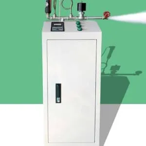
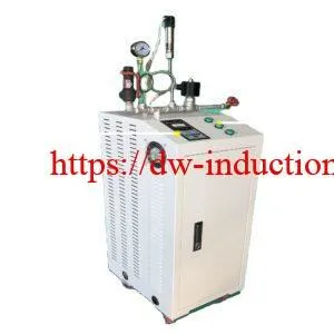
200°C–600+°C Superheater Steam Generator Induction-Superheated Steam Induction Heater
3.1 Electromagnetic Induction — Faraday’s Law
3.2 Joule Heating — Direct Pipe Wall Heating
3.3 Skin Effect — Frequency-Controlled Penetration Depth
4.1 Comprehensive Advantages vs Conventional Methods
Complete Material Selection Table by Temperature Range
6.1 Multi-Stage System Configuration by Target Temperature
6.2 Four-Stage Configuration for 600°C Target (Detailed)
7.1 Industrial Application Matrix by Temperature Range
8.1 Classification by System Architecture
8.2 Classification by Power Supply Technology
9.1 Core System Components (Continued)
9.2 Complete Technical Parameters Table
1. Introduction
Superheated steam at temperatures from 200 °C to over 600 °C is widely used in power generation, chemical processing, sterilization, drying, and advanced materials manufacturing. Traditional fossil‑fuel or electric resistance superheaters can be bulky, slow to respond, and produce combustion emissions. Induction‑based superheated steam generators use electromagnetic heating to deliver fast, controllable, and compact superheating with low local emissions and high efficiency. This article explains the technology, design choices, materials, system layouts, and selection criteria for industrial applications.
The superheater steam generator induction — also widely known as the electromagnetic induction steam superheater — has emerged as the definitive technology platform for meeting this broad spectrum of superheated steam temperature requirements, delivering superior energy efficiency, unprecedented temperature control precision, zero direct combustion emissions, and seamless integration with modern industrial automation systems that conventional gas-fired and resistance-heated superheaters fundamentally cannot match.
This comprehensive technical guide covers everything industrial engineers, procurement specialists, and plant managers need to understand about superheated steam induction generators operating across the full 200°C to 600+°C temperature range — from fundamental operating principles and pipe material selection to complete system configurations, equipment specifications, and expert guidance on selecting the optimal system for specific industrial applications.
2. What Is a Superheater Steam Generator Induction?
A superheater steam induction generator is a purpose-engineered industrial thermal processing system that applies the principles of electromagnetic induction heating to raise the temperature of steam — either from saturated steam conditions or from an existing lower superheated state — to a precisely controlled higher superheated temperature within the range of 200°C to 600°C and above, depending on the specific industrial application requirements and pipe material selection.
The system achieves this steam temperature elevation by generating heat directly within the wall of a metallic steam pipe through electromagnetic induction — inducing eddy currents and magnetic hysteresis losses within the pipe wall material using a high-frequency alternating electromagnetic field produced by a water-cooled induction coil energized by an IGBT (Insulated Gate Bipolar Transistor) solid-state power supply. The heated pipe wall then transfers thermal energy to the flowing steam through forced convective heat transfer, progressively raising the steam temperature along the heated pipe length until the target outlet temperature is achieved.
Superheated Steam Induction Generator — Key Defining Characteristics:
→ Heat source: Electromagnetic induction (no combustion)
→ Heating location: Directly within metallic pipe wall
→ Temperature range: 200°C to 600+°C (material dependent)
→ Energy efficiency: 88~96% (electrical to steam thermal)
→ Temperature control: ±2~5°C accuracy (PID controlled)
→ Startup time: 3~8 minutes (vs 30~90 min for gas-fired)
→ Direct CO₂ emissions: Zero
→ Maintenance: Minimal (no burners, no combustion components)
→ Automation: Full PLC/SCADA/Industry 4.0 compatible
→ Scale: 10 kW laboratory systems to 5,000+ kW industrial plants
3. Working Principle
The superheated steam induction generator operates on three fundamental and simultaneous physical principles that together produce efficient, controllable, and uniform pipe wall heating across the full 200°C to 600+°C operating temperature range.
3.1 Electromagnetic Induction — Faraday’s Law
High-frequency alternating current from the IGBT power supply flows through the water-cooled copper induction coil wound around the steam pipe. This alternating current creates a rapidly changing magnetic field that penetrates the metallic pipe wall, inducing an electromotive force (EMF) within the conductive pipe material according to Faraday’s Law of Electromagnetic Induction — driving eddy currents through the pipe wall’s electrical resistance and generating heat directly within the pipe wall material with no physical contact required between the coil and the pipe.
3.2 Joule Heating — Direct Pipe Wall Heating
The eddy currents induced within the pipe wall flow through the pipe material’s electrical resistance, converting electromagnetic energy directly into thermal energy according to Joule’s Law: P = I²R. This direct conversion of electromagnetic energy to heat within the pipe wall itself — rather than transferring heat from an external source through multiple thermal resistance layers — is the fundamental reason why induction heating achieves energy efficiencies of 88 to 96 percent, far exceeding the 45 to 70 percent typical of gas-fired and resistance-heated alternatives.
3.3 Skin Effect — Frequency-Controlled Penetration Depth
Skin Depth Formula:
δ = 503 × √(ρ / (μr × f))
Where:
δ = current penetration depth (mm)
ρ = electrical resistivity (μΩ·m)
μr = relative magnetic permeability
f = operating frequency (Hz)
Key Principle:
→ Match skin depth to pipe wall thickness
→ Optimal when δ ≈ 0.7 × wall thickness
→ Maximizes heating efficiency and uniformity
4. Advantages
4.1 Comprehensive Advantages vs Conventional Methods
| Performance Parameter | Induction Generator | Gas-Fired Superheater | Electric Resistance | Steam-to-Steam HX |
| Energy Efficiency | ✅ 88~96% | ❌ 45~70% | ⚠️ 75~85% | ⚠️ 78~88% |
| Temperature Accuracy | ✅ ±2~5°C | ❌ ±20~50°C | ⚠️ ±10~20°C | ❌ ±15~35°C |
| Max Achievable Temp | ✅ 600+°C | ✅ 600+°C | ⚠️ 500°C (element limit) | ⚠️ Limited by HX design |
| Startup Time | ✅ 3~8 min | ❌ 30~90 min | ❌ 15~45 min | ❌ 20~60 min |
| Direct CO₂ Emissions | ✅ Zero | ❌ Very High | ✅ Zero | ✅ Zero |
| Temperature Response | ✅ < 10 sec | ❌ Minutes | ⚠️ 1~3 min | ❌ Minutes |
| Maintenance Frequency | ✅ Low | ❌ High | ⚠️ Medium | ⚠️ Medium |
| Footprint | ✅ Compact | ❌ Large | ⚠️ Medium | ❌ Large |
| Hazardous Area Use | ✅ ATEX capable | ❌ Flame risk | ✅ Possible | ✅ Possible |
| Automation Integration | ✅ Seamless | ⚠️ Complex | ✅ Good | ⚠️ Moderate |
| Scalability | ✅ 10kW~5MW | ⚠️ Limited | ⚠️ Limited | ❌ Complex |
| Operating Cost (10yr) | ✅ Lowest | ❌ Highest | ⚠️ Medium | ⚠️ Medium-High |
Energy Savings vs Gas-Fired Superheater:
→ Efficiency improvement: +25~45 percentage points
→ Annual energy cost reduction: 28~42%
→ Typical payback period: 2.5~4.5 years
Operational Benefits:
→ Zero warmup time losses = +15~25% productive operating hours
→ ±2~5°C accuracy = measurably improved product quality consistency
→ Instant load response = precise process control capability
→ No combustion components = 60~80% reduction in maintenance costs
Environmental Benefits:
→ Zero direct NOx emissions (vs 150~400 mg/Nm³ for gas-fired)
→ Zero direct CO₂ emissions (scope 1 carbon footprint = zero)
→ Supports ISO 14001, EU Green Deal, and carbon neutrality targets
→ Qualifies for green energy incentives and carbon credit schemes
5. What Material Is Suitable for Steam Superheating?
Pipe material selection is the single most critical engineering decision in superheated steam induction generator design, directly determining the maximum achievable steam temperature, system reliability, service life, electromagnetic heating efficiency, and total system cost.
Complete Material Selection Table by Temperature Range
| Temperature Range | Recommended Material | Standard | Max Temp | Allowable Stress | Magnetic? | Induction Efficiency | Cost Index |
| 200~350°C | 20G Carbon Steel | GB 5310 | 450°C | 115 MPa @350°C | ✅ Yes | ✅✅ 92~96% | 💲 Lowest |
| 200~380°C | A106 Gr.B | ASTM A106 | 425°C | 110 MPa @350°C | ✅ Yes | ✅✅ 90~95% | 💲 Low |
| 300~480°C | 15CrMo | GB 5310 | 550°C | 130 MPa @400°C | ✅ Yes | ✅ 88~93% | 💲💲 Medium |
| 350~520°C | P11 (1.25Cr-0.5Mo) | ASTM A335 | 550°C | 135 MPa @450°C | ✅ Yes | ✅ 86~92% | 💲💲 Medium |
| 400~570°C | P22 (2.25Cr-1Mo) | ASTM A335 | 600°C | 118 MPa @500°C | ✅ Yes | ✅ 85~91% | 💲💲 Medium |
| 450~620°C | P91 (9Cr-1Mo-V) | ASTM A335 | 650°C | 138 MPa @550°C | ✅ Yes | ✅ 83~90% | 💲💲💲 High |
| 500~650°C | P92 (9Cr-2W) | ASTM A335 | 680°C | 143 MPa @600°C | ✅ Yes | ✅ 82~89% | 💲💲💲 High |
| 500~650°C | 347H Stainless | ASTM A312 | 700°C | 98 MPa @600°C | ❌ No | ⚠️ 60~70% | 💲💲💲 High |
| 550~680°C | 321H Stainless | ASTM A312 | 700°C | 95 MPa @600°C | ❌ No | ⚠️ 60~70% | 💲💲💲 High |
| 600~750°C | 310S Stainless | ASTM A312 | 1,050°C | 88 MPa @700°C | ❌ No | ⚠️ 55~68% | 💲💲💲💲 V.High |
| 600+°C | Incoloy 800H | ASTM B407 | 900°C | 72 MPa @700°C | ❌ No | ⚠️ 62~72% | 💲💲💲💲💲 Premium |

6. System Configuration
6.1 Multi-Stage System Configuration by Target Temperature
| Target Temp | Inlet Condition | Stages Required | Total Power (1,000 kg/hr) | Pipe Material | Control Strategy |
| 200°C | Saturated ~120°C | 1 Stage | 30~50 kW | 20G Carbon Steel | Single PID |
| 300°C | Saturated ~130°C | 2~3 Stages | 100~140 kW | 20G / A106 Gr.B | Cascade PID |
| 400°C | Saturated ~150°C | 3 Stages | 190~230 kW | 15CrMo / P11 | Cascade PID + FF |
| 500°C | Saturated ~170°C | 3~4 Stages | 290~340 kW | P22 / P91 | Multi-loop PID + FF |
| 600°C | Saturated ~180°C | 4 Stages | 390~450 kW | P91 / P92 / 347H | Multi-loop PID + FF |
| 650+°C | Saturated ~200°C | 4~5 Stages | 460~540 kW | 310S / Incoloy 800H | Advanced multi-loop |
6.2 Four-Stage Configuration for 600°C Target (Detailed)
FOUR-STAGE SYSTEM FOR HEATING SATURATED STEAM TO 600°C:
Saturated Steam Inlet (~180°C / 1.0 MPa)
↓
┌─────────────────────────────────────────────────────────┐
│ STAGE 1 — Drying and Initial Superheat │
│ Temperature Rise: 180°C → 280°C (ΔT = 100°C) │
│ Power Share: 28% of total │
│ Pipe Material: 15CrMo (ferromagnetic, high efficiency) │
│ IGBT Frequency: 10,000~25,000 Hz │
│ Induction Efficiency: 88~93% │
│ Control Accuracy: ±8°C │
└──────────────────────────┬──────────────────────────────┘
↓ 280°C
┌─────────────────────────────────────────────────────────┐
│ STAGE 2 — Mid-Temperature Heating │
│ Temperature Rise: 280°C → 400°C (ΔT = 120°C) │
│ Power Share: 30% of total │
│ Pipe Material: P22 (ferromagnetic, strong) │
│ IGBT Frequency: 5,000~15,000 Hz │
│ Induction Efficiency: 85~91% │
│ Control Accuracy: ±6°C │
└──────────────────────────┬──────────────────────────────┘
↓ 400°C
┌─────────────────────────────────────────────────────────┐
│ STAGE 3 — High-Temperature Heating │
│ Temperature Rise: 400°C → 530°C (ΔT = 130°C) │
│ Power Share: 27% of total │
│ Pipe Material: P91 (ferromagnetic, high strength) │
│ IGBT Frequency: 3,000~10,000 Hz │
│ Induction Efficiency: 83~90% │
│ Control Accuracy: ±5°C │
└──────────────────────────┬──────────────────────────────┘
↓ 530°C
┌─────────────────────────────────────────────────────────┐
│ STAGE 4 — Precision Final Heating │
│ Temperature Rise: 530°C → 600°C (ΔT = 70°C) │
│ Power Share: 15% of total │
│ Pipe Material: 347H / P92 (high temperature stable) │
│ IGBT Frequency: 2,000~8,000 Hz │
│ Induction Efficiency: 80~88% │
│ Control Accuracy: ±3°C │
└──────────────────────────┬──────────────────────────────┘
↓
600°C Superheated Steam Outlet
Accuracy: ±3~5°C
7. Applications
7.1 Industrial Application Matrix by Temperature Range
| Temperature Range | Industry Sector | Specific Application | Key Requirement | System Scale |
| 200~250°C | Food & Beverage | Sterilization, pasteurization, cooking | Dry steam, food-grade | 30~200 kW |
| 250~320°C | Pharmaceutical | Validated sterilization (autoclaving) | Precise ±2°C, traceable | 50~300 kW |
| 280~350°C | Textile Industry | Fabric heat-setting, drying | Uniform temperature | 100~500 kW |
| 300~380°C | Paper & Pulp | Drying cylinders, calender rolls | High flow, stable temp | 300~2,000 kW |
| 300~400°C | Rubber & Plastics | Vulcanization, molding, extrusion | Precise cure temp | 50~400 kW |
| 350~450°C | Chemical Processing | Reactor heating, distillation columns | Chemical compatibility | 200~2,000 kW |
| 400~500°C | Oil & Gas | Pipeline preheating, process steam | ATEX certified | 100~1,000 kW |
| 450~550°C | Power Generation | Small turbine superheating, ORC | High efficiency | 300~3,000 kW |
| 500~600°C | Advanced Materials | Carbon fiber treatment, ceramics | Ultra-precise control | 100~800 kW |
| 550~650°C | Petrochemical | Catalytic cracking, reforming | High temp stability | 500~5,000 kW |
| 600+°C | Research & Development | High-temperature process research | Flexible, precise | 10~500 kW |
8. Types
8.1 Classification by System Architecture
| Type | Description | Temperature Range | Power Range | Best For | Advantages |
| Single-Stage Inline | One heating coil section, single IGBT | 200~350°C | 10~300 kW | Simple processes, limited space | Lowest cost, simplest installation |
| Multi-Stage Series | 2~5 independent stages in series | 200~650°C | 50~5,000 kW | Wide temperature range requirements | Precise zonal control, high accuracy |
| Parallel Multi-Pipe | Multiple pipes heated simultaneously | 200~500°C | 500~10,000 kW | Very high flow rates | Maximum throughput capacity |
| Modular Expandable | Base unit with add-on modules | 200~600°C | 30~3,000 kW | Growing production needs | Future capacity expansion |
| Portable / Skid-Mounted | Complete system on mobile skid | 200~450°C | 10~500 kW | Field applications, PWHT | Mobility, rapid deployment |
| Integrated Boiler-Superheater | Combined steam generation + superheating | 200~500°C | 50~2,000 kW | New installations | Single-system solution |

8.2 Classification by Power Supply Technology
IGBT Resonant Inverter (Most Common — Recommended):
→ Technology: Full-bridge IGBT resonant inverter
→ Frequency range: 1,000~500,000 Hz
→ Efficiency: 92~96%
→ Power range: 10 kW~5,000 kW per unit
→ Control: Digital PWM, PLC-integrated
→ Advantages: Highest efficiency, precise control, reliable
→ Best for: All industrial steam superheating applications
SCR Thyristor Power Supply (Legacy Technology):
→ Technology: Silicon controlled rectifier
→ Frequency range: 50~10,000 Hz
→ Efficiency: 85~92%
→ Power range: 100 kW~50,000 kW
→ Advantages: Very high power capability, proven technology
→ Best for: Very large-scale low-frequency applications
Transistor Power Supply (High Frequency):
→ Technology: BJT/MOSFET transistor inverter
→ Frequency range: 100,000~1,000,000 Hz
→ Efficiency: 88~94%
→ Power range: 1 kW~100 kW
→ Best for: Small-scale high-frequency applications
9. Equipment Components and Technical Parameters
| Component | Function | Key Specifications | Material / Technology |
| IGBT Power Supply | Converts grid power to high-frequency AC | 10~5,000 kW, 1~500 kHz, η=92~96% | IGBT semiconductor, water-cooled |
| Induction Coil Assembly | Generates alternating magnetic field | Copper tube OD 12~30mm, 6~18 turns | Water-cooled copper, ceramic insulated |
| Heating Pipe Section | Steam conduit and heating element | DN25~DN300, wall 4~25mm | 20G / 15CrMo / P91 / 310S / 800H |
| Impedance Matching Unit | Optimizes power transfer efficiency | Tuned to coil+pipe resonance | Capacitor bank, copper bus bars |
| Magnetic Flux Concentrator | Increases electromagnetic coupling | μr=500~50,000, covers 60~80% of coil | Ferrite / silicon steel / nanocrystalline |
| Cooling Water System | Cools IGBT, coil, and capacitors | 20~150 L/min, ΔT=15~20°C | Closed-loop chiller or cooling tower |
| Thermal Insulation System | Minimizes heat losses |
9.1 Core System Components (Continued)
| Component | Function | Key Specifications | Material / Technology |
| Thermal Insulation System | Minimizes heat losses from pipe | 3-layer system, heat loss < 5% | Ceramic fiber + calcium silicate + Al cladding |
| Temperature Sensors | Measure steam and pipe wall temperature | ±1.5~3°C accuracy, 0~800°C range | K-type / N-type thermocouple, IR pyrometer |
| Pressure Transmitters | Monitor steam pressure continuously | 0~10 MPa range, ±0.5% accuracy | Piezoelectric, 4~20mA output |
| Mass Flow Meter | Measure steam mass flow rate | ±0.5~1.0% accuracy | Vortex / Coriolis type |
| PLC Control System | Executes control logic and protection | Siemens S7-1500 / AB ControlLogix | Redundant CPU option available |
| HMI Touchscreen | Operator interface and visualization | 15~21 inch industrial touchscreen | IP65 rated, SCADA compatible |
| Safety Relief Valve | Overpressure protection | Set at 110% design pressure | Spring-loaded, ASME certified |
| Isolation Valves | System isolation for maintenance | Full-bore ball valve / gate valve | High-temperature rated, 316SS trim |

9.2 Complete Technical Parameters Table
| Parameter Category | Parameter | 200~350°C System | 350~500°C System | 500~650°C System |
| Steam Process | Inlet condition | Saturated / low superheat | Saturated / superheated | Saturated / superheated |
| Inlet temperature range | 120~200°C | 150~250°C | 170~300°C | |
| Outlet temperature | 200~350°C | 350~500°C | 500~650°C | |
| Temperature accuracy | ±2~5°C | ±3~6°C | ±4~8°C | |
| Operating pressure range | 0.2~3.0 MPa | 0.5~5.0 MPa | 1.0~8.0 MPa | |
| Maximum pressure drop | 0.02~0.05 MPa | 0.03~0.08 MPa | 0.05~0.12 MPa | |
| Steam flow rate range | 100~10,000 kg/hr | 200~8,000 kg/hr | 300~6,000 kg/hr | |
| Electrical | Input voltage | 380V / 660V 3-phase | 380V / 660V 3-phase | 660V / 6kV 3-phase |
| Input frequency | 50 / 60 Hz | 50 / 60 Hz | 50 / 60 Hz | |
| IGBT output frequency | 5,000~50,000 Hz | 3,000~25,000 Hz | 1,000~15,000 Hz | |
| System power range | 10~1,500 kW | 50~3,000 kW | 100~5,000 kW | |
| Overall efficiency | 90~96% | 88~94% | 85~92% | |
| Power factor | > 0.95 | > 0.95 | > 0.93 | |
| THD (Total Harmonic Distortion) | < 5% | < 5% | < 8% | |
| Pipe Material | Recommended material | 20G / A106 Gr.B | P11 / P22 / P91 | P91 / P92 / 347H |
| Pipe design temperature | 250~420°C | 420~580°C | 580~720°C | |
| Pipe design pressure | 0.5~4.0 MPa | 1.0~6.0 MPa | 2.0~10.0 MPa | |
| Minimum wall thickness | 4~8 mm | 6~15 mm | 8~25 mm | |
| Pipe inspection standard | ASME B31.1 | ASME B31.1 | ASME B31.1 / B31.3 | |
| Induction Coil | Coil material | Copper tube | Copper tube | Copper tube |
| Cooling method | Water-cooled | Water-cooled | Water-cooled | |
| Coil-pipe gap | 5~10 mm | 6~12 mm | 8~15 mm | |
| Maximum coil surface temp | 80°C | 80°C | 80°C | |
| Coil insulation class | Class H (180°C) | Class H (180°C) | Class H+ (200°C) | |
| Cooling System | Cooling water flow | 20~80 L/min | 40~150 L/min | 80~300 L/min |
| Cooling water inlet temp | ≤ 30°C | ≤ 28°C | ≤ 25°C | |
| Cooling water outlet temp | ≤ 45°C | ≤ 45°C | ≤ 42°C | |
| Cooling water pressure | 0.2~0.4 MPa | 0.2~0.5 MPa | 0.3~0.6 MPa | |
| Control System | Control algorithm | PID / Cascade PID | Cascade PID + FF | Multi-loop PID + FF |
| Temperature scan rate | 500 ms | 200 ms | 100 ms | |
| Power response time | < 50 ms | < 50 ms | < 50 ms | |
| Data logging retention | 12 months | 24 months | 36 months | |
| Remote communication | Ethernet / Modbus | Ethernet / Profibus | Ethernet / OPC-UA | |
| Physical | Startup time to setpoint | 3~6 minutes | 4~8 minutes | 6~12 minutes |
| Noise level | < 75 dB(A) | < 78 dB(A) | < 82 dB(A) | |
| Protection rating | IP54 | IP54 | IP55 | |
| Direct CO₂ emissions | Zero | Zero | Zero | |
| Design service life | 20+ years | 20+ years | 15~20 years |
10. How to Choose
Specifying a 600°C induction steam generator requires careful engineering calculations. Consider the following steps to ensure you choose the right system:
- Define the Thermodynamics (Power Calculation):
You must know your exact mass flow rate (kg/hr), input steam temperature/pressure, and target output temperature/pressure. Using steam tables, calculate the specific enthalpy difference (Δh) between the inlet and outlet states.
Formula: Power (kW) = Mass Flow (kg/s) × Δh (kJ/kg). Always add a 15-20% safety margin for high-temperature applications. - Select the Proper Metallurgy:
Do not compromise on materials. If your target is 400°C, P11 or carbon steel might suffice. If your target is 650°C, you must specify 310S or Incoloy. Ensure the manufacturer understands the induction frequency requirements for non-magnetic alloys. - Evaluate Pressure Drop:
Heating steam causes it to expand rapidly. Ensure the diameter of the heating pipes is sized correctly to prevent unacceptable pressure drops across the superheater. - Check Power Supply Capabilities:
Ensure your facility has the electrical infrastructure (transformers, switchgear) to handle the high kW loads required. Industrial systems often require 380V, 480V, or 690V 3-phase power. - Look for Advanced Control Integration:
Choose a system with a robust PLC that can accept 4-20mA signals from your existing plant flow meters to automatically modulate induction power based on real-time steam flow fluctuations.
11. Conclusion
The 200°C–600+°C superheater steam generator induction system is a cutting‑edge solution for industries requiring high‑temperature, high‑efficiency, and clean steam. By leveraging electromagnetic induction technology, it delivers fast heating, precise control, low operating cost, and environmental benefits.
The transition from 200°C saturated steam to 600°C+ ultra-superheated steam opens the door to next-generation industrial processes, from green hydrogen production to advanced chemical synthesis. The Superheater Steam Generator Induction system represents the pinnacle of modern thermal engineering. By eliminating fossil fuels, maximizing thermal efficiency via internal eddy current heating, and utilizing advanced metallurgy like Incoloy and 310S stainless steel, industries can achieve unprecedented temperature control and reliability. As global industries push toward decarbonization and smarter process controls, electromagnetic induction stands as the definitive future of high-temperature process heating.

12. FAQ
Q1: Can induction steam generators reach temperatures above 600 °C?
Yes, with suitable materials and multi‑stage design, temperatures above 600 °C are achievable.
Q2: Is induction steam superheating safe at high pressure?
Yes, when designed according to pressure vessel and piping standards.
Q3: Does induction heating contact steam directly?
No, heating is indirect through the pipe wall.
Q4: What is the typical efficiency of induction steam superheaters?
Typically between 80% and 95%.
Q5: Can it replace fuel‑fired superheaters?
In many applications, yes—especially where clean and precise heating is required.
Q6: Is the system suitable for continuous operation?
Yes, induction steam generators are designed for 24/7 industrial use.
Related products
-

Steel, Titanium,Brass Induction Billet Forging Heater For Extrusion Aluminium, Copper Billet Bar Dies Rod
-
Induction Steam Boiler
-
Steel Billet Heating Furnace with Induction For forging rolling mills and extrusion bars-billets-rods
-
Steam Boilers With Magnetic Induction Heating
-
Induction Straightening and Alignment of Frames and Support Structures in Heavy Machinery